Gigabyte GA-8S661FXM-775 Manual
Gigabyte GA-8S661FXM-775 Manual
 |
View all Gigabyte GA-8S661FXM-775 manuals
Add to My Manuals
Save this manual to your list of manuals |
Gigabyte GA-8S661FXM-775 manual content summary:
- Gigabyte GA-8S661FXM-775 | Manual - Page 1
GA-8S661FXM-775 Intel® Pentium® 4 LGA775 Processor Motherboard User's Manual Rev. 1102 12ME-61FXM775-1102 - Gigabyte GA-8S661FXM-775 | Manual - Page 2
Motherboard GA-8S661FXM-775 Sept. 29, 2004 Motherboard GA-8S661FXM-775 Sept. 29, 2004 - Gigabyte GA-8S661FXM-775 | Manual - Page 3
the following: „ For detailed product information and specifications, please carefully read the "User's Manual." „ For detailed information related to Gigabyte's unique features, please go to the "Technology Guide" section on Gigabyte's website to read or download the information you need. For more - Gigabyte GA-8S661FXM-775 | Manual - Page 4
Table of Contents GA-8S661FXM-775 Motherboard Layout 6 Block Diagram ...7 Chapter 1 Hardware Installation 9 1-1 Considerations Prior to Installation 9 1-2 Feature Summary 10 1-3 Installation of the CPU and Heatsink 12 1-3-1 Installation of the CPU 12 1-3-2 Installation of the Heatsink 13 1-4 - Gigabyte GA-8S661FXM-775 | Manual - Page 5
3-5 Contact Us ...51 Chapter 4 Appendix ...53 4-1 Unique Software Utility 53 4-1-1 Xpress Recovery2 Introduction 53 4-1-2 BIOS Flash Method Introduction 55 4-1-3 Serial ATA BIOS Setting Utility Introduction 64 4-1-4 2 / 4 / 6 Channel Audio Function Introduction 71 4-2 Troubleshooting 79 - 5 - - Gigabyte GA-8S661FXM-775 | Manual - Page 6
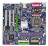
GA-8S661FXM-775 Motherboard Layout COMA KB_MS ATX_12V COMB LGA775 CPU_FAN ATX FDD VGA LPT GA-8S661FXM-775 DDR1 DDR2 USB USB LAN AUDIO F_AUDIO AGP ICS1883 SiS 661FX IDE2 IDE1 IT8705AF BIOS CODEC CD_IN SUR_CEN SPDIF_IO PCI1 PCI2 BAT PCI3 F_USB1 F_USB2 SiS 964 CLR_CMOS SYS _FAN - Gigabyte GA-8S661FXM-775 | Manual - Page 7
LGA775 Processor CPUCLK+/- (133/200MHz) AGP 4X/8X AGPCLK (66MHz) VGA Port Host Interface 266/333/400MHz DDR RAM SiS 661FX HCLK+/- (100/133/200MHz) 3 PCI ICS1883 SiS 964 133MHz 33 MHz 14.318 MHz 48 MHz 2 Serial ATA BIOS LPC BUS IT8705AF Floppy LPT Port AC97 Link PCICLK (33MHz) MIC - Gigabyte GA-8S661FXM-775 | Manual - Page 8
- 8 - - Gigabyte GA-8S661FXM-775 | Manual - Page 9
instructions below: 1. Please turn off the computer and unplug its power cord. 2. When handling the motherboard , avoid touching any metal leads or connectors. 3. It is best to wear an electrostatic discharge (ESD) cuff when handling electronic components (CPU, RAM motherboard problem manual - Gigabyte GA-8S661FXM-775 | Manual - Page 10
In ; Line Out ; MIC In Š Supports 2 / 4 / 6 channel audio Š SPDIF In/Out connection Š CD In connection Š Supports Jack-Sensing function Š IT8705AF Š CPU / System fan speed detection Š System voltage detection Š CPU temperature detection Š CPU Smart Fan Control GA-8S661FXM-775 Motherboard - 10 - - Gigabyte GA-8S661FXM-775 | Manual - Page 11
striping (RAID 0) or mirroring (RAID 1) function - supports JBOD function - supports data transfer rate of up to 150 MB/s - supports hot plugging function - supports a maximum of 2 SATA connections Use of licensed AWARD BIOS Supports Q-Flash Supports @BIOS Supports EasyTune Micro-ATX form factor; 24 - Gigabyte GA-8S661FXM-775 | Manual - Page 12
the proper specifications, please do so according to your hardware specifications including the CPU, graphics card, memory, hard drive, etc. that might cause damage to the CPU during installation.) GA-8S661FXM-775 Motherboard - 12 - Fig. 4 Once the CPU is properly inserted, please replace the - Gigabyte GA-8S661FXM-775 | Manual - Page 13
the CPU and make sure the push pins aim to the pin hole on the motherboard.Pressing down the push pins diagonally. Fig. 4 Please make sure the Male and Female push pin are joined closely. (for detailed installation instructions, please refer to the heatsink installation section of the user manual - Gigabyte GA-8S661FXM-775 | Manual - Page 14
DIMM memory module vertically into the DIMM socket. Then push it down. Fig.2 Close the plastic clip at both edges of the DIMM sockets to lock the DIMM module. Reverse the installation steps when you wish to remove the DIMM module. DDR memory module Fig. 1 Fig. 2 GA-8S661FXM-775 Motherboard - 14 - Gigabyte GA-8S661FXM-775 | Manual - Page 15
instruction expansion slot in motherboard. 4. Be BIOS. 8. Install related driver from the operating system. Installing a AGP expansion card: AGP Card Please carefully pull out the small white-drawable bar at the end of the AGP slot when you try to install/uninstall the VGA card. Please align the VGA - Gigabyte GA-8S661FXM-775 | Manual - Page 16
port. VGA Port Monitor can be connected to VGA port. supports USB controller. If your OS does not supportUSB controller, please contact OS vendor for possible patch or driver upgrade. For more information please contact your OS or device(s) vendors. LAN Port The LAN GA-8S661FXM-775 Motherboard - 16 - - Gigabyte GA-8S661FXM-775 | Manual - Page 17
English 1-7 Connectors Introduction 1 3 2 16 8 11 9 12 1) ATX_12V 2) ATX 3) CPU_FAN 4) SYS_FAN 5) IDE1/IDE2 6) FDD 7) SATA0/SATA1 8) F_AUDIO 9) SUR_CEN 6 5 18 15 4 7 10 13 14 17 10) F_PANEL 11) CD_IN 12) SPDIF_IO 13) F_USB1/F_USB2 14) CI 15) CLR_CMOS 16) COMB 17) PWR_LED 18) BAT - 17 - - Gigabyte GA-8S661FXM-775 | Manual - Page 18
Align the power connector with its proper location on the motherboard and connect tightly. The ATX_12V power connector mainly supplies power to the CPU. If the ATX_12V power connector is not connected, the ) 15 GND 16 GND 17 GND 18 -5V 19 VCC 20 VCC GA-8S661FXM-775 Motherboard - 18 - - Gigabyte GA-8S661FXM-775 | Manual - Page 19
the power to the cooler to prevent system overheating and failure. Caution! Please remember to connect the power to the CPU fan to prevent CPU overheating and failure. 1 CPU_FAN 1 SYS_FAN Pin No. 1 2 3 4 Definition GND +12V Sense Speed Control (Only for CPU_FAN) - 19 - Hardware Installation - Gigabyte GA-8S661FXM-775 | Manual - Page 20
connector is used to connect the FDD cable while the other end of the cable connects to the FDD drive. The types of FDD drives supported are: 360KB, 720KB, 1.2MB, 1.44MB and 2.88MB. Please connect the red power connector wire to the pin1 position. 34 33 2 1 GA-8S661FXM-775 Motherboard - 20 - - Gigabyte GA-8S661FXM-775 | Manual - Page 21
to 150MB/s transfer rate. Please refer to the BIOS setting for the Serial ATA and install the proper driver in order to work properly. 1 7 S_ATA ( buying support front audio panel connector, please contact your dealer. If you want to use "Front Audio" connector, you must remove the jumpers from - Gigabyte GA-8S661FXM-775 | Manual - Page 22
HD (IDE Hard Disk Active LED) SPEAK (Speaker Connector) RES (Reset Switch) PW (Power Switch) MSG (Message LED/Power/Sleep LED) NC GA-8S661FXM-775 Motherboard Reset Switch IDE Hard Disk Active LED Pin 1: LED anode(+) Pin 2: LED cathode(-) Pin 1: VCC(+) Pin 2- Pin 3: NC Pin 4: Data(-) Open: Normal - Gigabyte GA-8S661FXM-775 | Manual - Page 23
to the connector. 1 Pin No. Definition 1 CD-L 2 GND 3 GND 4 CD-R 12) SPDIF_IO (SPDIF In/ Out) The SPDIF output is capable of providing digital audio to external speakers or compressed AC3 data to an external Dolby Digital Decoder. Use this feature only when your stereo system has digital - Gigabyte GA-8S661FXM-775 | Manual - Page 24
Intrusion, Case Open) This 2-pin connector allows your system to detect if the chassis cover is removed. You can check the "Case Open" status in BIOS Setup. Pin No. Definition 1 Signal 1 2 GND GA-8S661FXM-775 Motherboard - 24 - - Gigabyte GA-8S661FXM-775 | Manual - Page 25
15) CLR_CMOS (Clear CMOS) You may clear the CMOS data to its default values by this jumper. To clear CMOS, temporarily short pins 1-2. To prevent improper use of this header, we do not include a jumper on it. Open: Normal 1 Short: Clear CMOS 1 16) COMB (COMB Connector) Be careful with the polarity - Gigabyte GA-8S661FXM-775 | Manual - Page 26
2 MPD- 3 MPD- 18) BAT (Battery) GA-8S661FXM-775 Motherboard Danger of explosion if battery is incorrectly replaced. Replace only with the same or equivalent type recommended by the manufacturer. Dispose of used batteries according to the manufacturer's instructions. If you want to erase CMOS - Gigabyte GA-8S661FXM-775 | Manual - Page 27
- 27 - Hardware Installation English - Gigabyte GA-8S661FXM-775 | Manual - Page 28
English GA-8S661FXM-775 Motherboard - 28 - - Gigabyte GA-8S661FXM-775 | Manual - Page 29
BIOS, either Gigabyte's Q-Flash or @BIOS utility can be used. Q-Flash allows the user to quickly and easily update or backup BIOS without entering the operating system. @BIOS is a Windows-based utility that does not require users to boot to DOS before upgrading BIOS but directly download and update - Gigabyte GA-8S661FXM-775 | Manual - Page 30
Exit Without Saving Esc: Quit F8: Q-Flash KLJI: Select Item F10: Save & Exit in standard compatible BIOS. „ Advanced BIOS Features This setup CPU autodetected temperature, voltage, and fan, speed. „ MB Intelligent Tweaker (M.I.T.) This setup page is to control CPU GA-8S661FXM-775 Motherboard - 30 - - Gigabyte GA-8S661FXM-775 | Manual - Page 31
system. „ Save & Exit Setup Save CMOS value settings to CMOS and exit setup. „ Exit Without Saving Abandon all CMOS value changes and exit setup. - 31 - BIOS Setup - Gigabyte GA-8S661FXM-775 | Manual - Page 32
disk. Hard drive information should be labeled on the outside drive casing. Enter the appropriate option based on this information. Cylinder Number of cylinders Head Number of heads Precomp Write precomp Landing Zone Landing zone Sector Number of sectors GA-8S661FXM-775 Motherboard - 32 - Gigabyte GA-8S661FXM-775 | Manual - Page 33
with 640K or more memory installed on the motherboard. Extended Memory The BIOS determines how much extended memory is present during the POST. This is the amount of memory located above 1 MB in the CPU's memory address map. Total Memory This item displays the memory size that used. - 33 - Gigabyte GA-8S661FXM-775 | Manual - Page 34
BIOS Features ` Hard Disk Boot Priority First Boot Device Second Boot Device Third Boot Device Boot Up Floppy Seek Password Check CPU you install supports Intel® LAN Select your boot device priority by LAN. Disabled Select your boot device priority by Disabled. GA-8S661FXM-775 Motherboard - 34 - - Gigabyte GA-8S661FXM-775 | Manual - Page 35
mode supported. (Default value) Disabled Disable CPU Hyper- Windows XP. Init Display First Select the first initiation of the monitor display from AGP or PCI VGA card. PCI Set Init Display First to PCI VGA card. AGP Set Init Display First to AGP VGA card.(Default value) - 35 - BIOS - Gigabyte GA-8S661FXM-775 | Manual - Page 36
Audio Onboard LAN device USB Controller USB Legacy Support SiS compatible with ATA33) IDE2 Conductor Cable Auto BIOS autodetects IDE2 conductor cable. (Default Value) Audio Enabled Disabled Autodetect AC97 audio function. (Default value) Disable AC97 audio function. GA-8S661FXM-775 Motherboard - Gigabyte GA-8S661FXM-775 | Manual - Page 37
LAN device Enabled Enable Onboard LAN device function. (Default value) Disabled Disable this function. USB Controller Enabled Enable USB Controller. (Default value) Disabled Disable USB Controller. USB Legacy Support Enabled Disabled Enable USB Legacy Support. Disable USB Legacy Support - Gigabyte GA-8S661FXM-775 | Manual - Page 38
[S1] Set suspend type to Power On Suspend under ACPI OS [S3] Set suspend type to Suspend to RAM under ACPI OS KLJI: Move Enter: Select F5: Previous Values +/-/PU/PD: Value F10: Save F6: Disable ModemRingOn function. Enable ModemRingOn function.(Default value) GA-8S661FXM-775 Motherboard - 38 - - Gigabyte GA-8S661FXM-775 | Manual - Page 39
Blinking The Power LED will be blinking during S1 state. (Default value) Dual/OFF The Power LED will be turned off or change color. - 39 - BIOS Setup - Gigabyte GA-8S661FXM-775 | Manual - Page 40
) Set IRQ 3,4,5,7,9,10,11,12,14,15 to PCI 2. Auto assign IRQ to PCI 3. (Default value) Set IRQ 3,4,5,7,9,10,11,12,14,15 to PCI 3. GA-8S661FXM-775 Motherboard - 40 - - Gigabyte GA-8S661FXM-775 | Manual - Page 41
the CPU temperature is between 20 and 65 degrees Celsius, the CPU fan speed will change depending on the actual CPU temperature. c. When the CPU temperature is lower than 20 degrees Celsius, CPU fan will stop spinning. Disabled Disable the CPU Smart FAN Control function. - 41 - BIOS Setup - Gigabyte GA-8S661FXM-775 | Manual - Page 42
set up the DRAM Timing by DRAM SPD data. Manual (Default value) This item allows user to set DRAM Timing manually. CAS Latency Setting 2T/2.5T/3T Set CAS Latency to 2T/2.5T/3T (Default value is 3T). Auto BIOS will automatically detect CAS Latency. GA-8S661FXM-775 Motherboard - 42 - - Gigabyte GA-8S661FXM-775 | Manual - Page 43
is enabled. 100~355 Select CPU Clock to 100MHz~355MHz. If you use a Pentium 4 processor with 800MHz FSB, please set "CPU Clock" to 200MHz. Incorrect using the AGP Clock (MHz) manually, the PCI Clock (MHz) will change automatically depending on the AGP Clock (MHz) you set. - 43 - BIOS Setup - Gigabyte GA-8S661FXM-775 | Manual - Page 44
MB Intelligent Tweaker (M.I.T.) Exit Without Saving Esc: Quit F8: Q-Flash KLJI: Select Item F10: Save & Exit Setup Load Fail-Safe Defaults Fail-Safe defaults contain the most appropriate values of the system parameters that allow minimum system performance. GA-8S661FXM-775 Motherboard - 44 - - Gigabyte GA-8S661FXM-775 | Manual - Page 45
Password Save & Exit Setup Exit Without Saving Esc: Quit F8: Q-Flash KLJI: Select Item F10: Save & Exit Setup Change/Set/Disable access only basic items. If you select "System" at "Password Check" in Advance BIOS Features Menu, you will be prompted for the password every time the system is - Gigabyte GA-8S661FXM-775 | Manual - Page 46
Standard CMOS Features Top Performance ` Advanced BIOS Features Load Fail-Safe Defaults ` Flash KLJI: Select Item F10: Save & Exit Setup Abandon all Data Type "Y" will quit the Setup Utility without saving to RTC CMOS. Type "N" will return to Setup Utility. GA-8S661FXM-775 Motherboard - Gigabyte GA-8S661FXM-775 | Manual - Page 47
- 47 - BIOS Setup English - Gigabyte GA-8S661FXM-775 | Manual - Page 48
English GA-8S661FXM-775 Motherboard - 48 - - Gigabyte GA-8S661FXM-775 | Manual - Page 49
Pictures below are shown in Windows XP. (1) Please make sure to install the latest service pack for Windows after OS installation and before installing motherboard drivers. (2) Insert the driver CD that came with your motherboard into your CD-ROM drive, the driver CD will auto start and - Gigabyte GA-8S661FXM-775 | Manual - Page 50
Applications This page displays all the tools that Gigabyte developed and some free software, you can choose anyone you want and press "install" to install them. 3-3 Driver CD Information This page lists the contents of software and drivers in this CD-title. GA-8S661FXM-775 Motherboard - 50 - - Gigabyte GA-8S661FXM-775 | Manual - Page 51
English 3-4 Hardware Information This page lists all device you have for this motherboard. 3-5 Contact Us You can also see the last page of this manual for contacts information details. - 51 - Drivers Installation - Gigabyte GA-8S661FXM-775 | Manual - Page 52
English GA-8S661FXM-775 Motherboard - 52 - - Gigabyte GA-8S661FXM-775 | Manual - Page 53
CD/DVD: Press any key to startup XpressRecovery2..... Boot from CD/DVD: Award Modular BIOS v6.00PG, An Energy Star Ally Copyright (C) 1984-2005, Award Software, Inc. GA-8S661FXM-775 F5a . . . . :BIOS Setup/Q-Flash, : Xpress Recovery2, For Boot Menu 11/07/2006-661FX-6A79HG0GC-00 - Gigabyte GA-8S661FXM-775 | Manual - Page 54
As this is a BIOS-related issue, it can be solved by BIOS update) GA-K8U GA-K8NXP-9 GA-8N-SLI Royal GA-K8U-9 GA-K8N Ultra-9 GA-8N-SLI Pro GA-K8NXP-SLI GA-K8NF-9 (PCB Ver. 1.0) GA-8N-SLI GA-K8N Ultra-SLI GA-K8NE (PCB Ver. 1.0) GA-K8N Pro-SLI GA-K8NMF-9 GA-8S661FXM-775 Motherboard - 54 - - Gigabyte GA-8S661FXM-775 | Manual - Page 55
refer to Part Two. Part One: Updating BIOS with Q-FlashTM Utility on Dual BIOS Motherboards. Some of Gigabyte motherboards are equipped with dual BIOS. In the BIOS menu of the motherboards supporting Q-Flash and Dual BIOS, the Q-Flash utility and Dual BIOS utility are combined in the same screen - Gigabyte GA-8S661FXM-775 | Manual - Page 56
User Password Save & Exit Setup Exit Without Saving ESC: Quit F8: Dual BIOS/Q-Flash F3: Change Language F10: Save & Exit Setup Time, Date, Hard Disk the Q-Flash/Dual BIOS utility. Pressing the buttons mentioned on your keyboards to perform these actions. GA-8S661FXM-775 Motherboard - 56 - - Gigabyte GA-8S661FXM-775 | Manual - Page 57
to the BIOS file you want to flash and press Enter. In this example, we only download one BIOS file to the floppy disk so only one BIOS file, 8KNXPU.Fba, is listed. Please confirm again you have the correct BIOS file for your motherboard. Dual BIOS Utility Boot From Main Bios Main ROM Type - Gigabyte GA-8S661FXM-775 | Manual - Page 58
Primary Master : FUJITSU MPE3170AT ED-03-08 Primary Slave : None Secondary Master : CREATIVEDVD-RM DVD1242E BC101 Secondary Slave : None Press DEL to enter SETUP / Dual BIOS / Q-Flash / F9 For Xpress Recovery 09/23/2003-i875P-6A79BG03C-00 GA-8S661FXM-775 Motherboard - 58 - - Gigabyte GA-8S661FXM-775 | Manual - Page 59
F8: Dual BIOS/Q-Flash F3: Change Language F10: Save & Exit Setup Time, Date, Hard Disk Type... Press Y on your keyboard to save and exit. Part Two: Updating BIOS with Q-FlashTM Utility on Single-BIOS Motherboards. This part guides users of single-BIOS motherboards how to update BIOS using the - Gigabyte GA-8S661FXM-775 | Manual - Page 60
or ResEeSt CS:yRsteesmet F10:Power Off Do not trun off power or reset your system at this stage!! After BIOS file is read, you'll see a dialog box asking you "Are you sure to update BIOS?" Please do not take out the floppy disk when it begins flashing BIOS. GA-8S661FXM-775 Motherboard - 60 - - Gigabyte GA-8S661FXM-775 | Manual - Page 61
3. Press Y button on your keyboard after you are sure to update BIOS. Then it will begin to update BIOS. The progress of updating BIOS will be shown at the same time. Q-Flash Utility V1.30 Flash Type/Size SST 49LF002A 256K Keep DUMpdI aDtiantga BIEOnSaNbloew >>>>>>>U>>pd>a>t>e >B>I>O>S>f>r>om - Gigabyte GA-8S661FXM-775 | Manual - Page 62
New BIOS c. Please select "All Files" in dialog box while opening the downloaded BIOS file. d. Please search for BIOS unzip file, downloading from the Internet or any other methods (such as: 661fxm775.F1). e. Complete update process following the on-screen instructions. GA-8S661FXM-775 Motherboard - Gigabyte GA-8S661FXM-775 | Manual - Page 63
II, be sure that motherboard's model name in BIOS unzip file are the same as your motherboard's. Otherwise, your system won't boot. III. In method I, if the BIOS file you need cannot be found in @BIOSTM server, please go onto Gigabyte's web site for downloading and updating it according to method - Gigabyte GA-8S661FXM-775 | Manual - Page 64
spare drive can be attached. Such a drive will be activated to replace a failed drive that is part of a mirrored array. Due to the fault tolerance, if any RAID 1 drive fails, data access will not be affected as long as there are other working drives in the array. GA-8S661FXM-775 Motherboard - 64 - Gigabyte GA-8S661FXM-775 | Manual - Page 65
the hard drive connectors to their appropriate location on the motherboard ie. IDE, SCSI, or SATA. 3) Enter the motherboard BIOS and locate RAID a few seconds to press Ctrl-S before the window disappears. Silicon Integrated Systems Corp. RAID BIOS Setting Utility v1.05_964 (c) 2003-2005 Silicon - Gigabyte GA-8S661FXM-775 | Manual - Page 66
SiS RAID BIOS Setting Utility * Current Created Raid * RAID Setup RAID Type : JBOD RAID 0 RAID 1 : [Q] : Exit current menu Location Model Disk 1 Disk 2 ST3120026AS ST3120026AS Capacity 111GB 111GB Mode UDMA 6 UDMA 6 RAID Type Single Single Figure 4 GA-8S661FXM-775 Motherboard - Gigabyte GA-8S661FXM-775 | Manual - Page 67
unless you know well how to set every required item, like block size.) SiS RAID BIOS Setting Utility * Current Created Raid * RAID Setup RAID 0 Auto Create Manual Create : 1 [Q] : Exit current menu Location Model Disk 1 Disk 2 ST3120026AS ST3120026AS Capacity 111GB 111GB Mode UDMA - Gigabyte GA-8S661FXM-775 | Manual - Page 68
see the RAID array under the * Current Created Raid * list in the RAID Setup window (Figure 7). SiS RAID BIOS Setting Utility * Current Created Raid * RAID 0 : Disk 1 Disk 2 RAID Setup ST3120026AS 111GB 111GB UDMA 6 UDMA 6 RAID Type RAID0 RAID0 Figure 8 GA-8S661FXM-775 Motherboard - 68 - - Gigabyte GA-8S661FXM-775 | Manual - Page 69
to delete a RAID volume, simply press in the following window (Figure 9) and then use arrow keys to select the RAID sure to delete this RAID?" message appears, press to confirm your selections. SiS RAID BIOS Setting Utility * Current Created Raid * RAID 0 : Disk 1 Disk 2 RAID Setup Press - Gigabyte GA-8S661FXM-775 | Manual - Page 70
. (Each time you add a new hard drive to a RAID array, the RAID driver will have to be installed under Windows once for that hard drive. After that, the driver will not have to be installed.) Note: In the menu list, IAA_RAID refers to Intel ICH5R chipset. GA-8S661FXM-775 Motherboard - 70 - - Gigabyte GA-8S661FXM-775 | Manual - Page 71
Function Introduction The following setup is for Windows 98SE/2000/ME/XP. Please follow the steps below to enable the function! 2 Channel Audio Setup We recommend that you use speakers with amplifier to get the best sound effect if the stereo output is applied. STEP 1: Connect the stereo speakers - Gigabyte GA-8S661FXM-775 | Manual - Page 72
output check box. Clear the Only SURROUND-KIT check box and press OK. When the Environment setting is None, the sound would be performed as stereo mode (2-channel output). Please select other settings (ex: Living Room) for 4-channel output. GA-8S661FXM-775 Motherboard - 72 - Line Out Line In - Gigabyte GA-8S661FXM-775 | Manual - Page 73
to "Line Out",the rear channels to "Line In", and the Center/Subwoofer channels to "MIC In". MIC In Line Out STEP 2: After installing the audio driver, you'll find a Sound Effect icon on the lower right hand taskbar. Click the icon to select the function. Line In STEP 3: On the AC97 - Gigabyte GA-8S661FXM-775 | Manual - Page 74
same time. "SURROUND-KIT" is included in the GIGABYTE unique "Audio Combo Kit" as picture. STEP 1: Secure the metal bracket of the "Surround Kit" to the chassis back panel with a screw. STEP 2: Connect the "SURROUND-KIT" cable to the SUR_CEN connector on the M/B. GA-8S661FXM-775 Motherboard - 74 - - Gigabyte GA-8S661FXM-775 | Manual - Page 75
panel's "Line Out", the rear channels to SURROUND-KIT's REAR R/L, and the Center/Subwoofer channels to SURROUND-KIT's SUB CENTER. STEP 4: After installing the audio driver, you'll find a Sound Effect icon on the lower right hand taskbar. Click the icon to select the function. STEP 5: On the AC97 - Gigabyte GA-8S661FXM-775 | Manual - Page 76
bracket of the SPDIF Output device to the chassis back panel with a screw. STEP 2: Connect the SPDIF device cable to the SPDIF_IO connector on the motherboard. STEP 3: Connect SPDIF to the SPDIF decoder. GA-8S661FXM-775 Motherboard - 76 - - Gigabyte GA-8S661FXM-775 | Manual - Page 77
DirectX8.1 first to enable Jack-Sensing support for Windows 98SE/2000 /ME. Jack-Sensing includes 2 parts: AUTO and MANUAL. Following is an example for 2 channels (Windows XP): Introduction of audio connectors You may connect CDROM, Walkman or other audio input devices to Line In jack, speakers - Gigabyte GA-8S661FXM-775 | Manual - Page 78
English If you set wrong with the connectors, the warning message will come out as right picture. Manual setting: If the device picture shows different from what you set, please press "Manual Selection" to set. GA-8S661FXM-775 Motherboard - 78 - - Gigabyte GA-8S661FXM-775 | Manual - Page 79
English 4-2 Troubleshooting Below is a collection of general asked questions. To check general asked questions based on a specific motherboard model, please log on to www.gigabyte.com.tw Question 1: I cannot see some options that were included in previous BIOS after updating BIOS. Why? Answer: - Gigabyte GA-8S661FXM-775 | Manual - Page 80
English GA-8S661FXM-775 Motherboard - 80 - - Gigabyte GA-8S661FXM-775 | Manual - Page 81
- 81 - Appendix English - Gigabyte GA-8S661FXM-775 | Manual - Page 82
English GA-8S661FXM-775 Motherboard - 82 - - Gigabyte GA-8S661FXM-775 | Manual - Page 83
- 83 - Appendix English - Gigabyte GA-8S661FXM-775 | Manual - Page 84
English GA-8S661FXM-775 Motherboard - 84 - - Gigabyte GA-8S661FXM-775 | Manual - Page 85
- 85 - Appendix English - Gigabyte GA-8S661FXM-775 | Manual - Page 86
English GA-8S661FXM-775 Motherboard - 86 - - Gigabyte GA-8S661FXM-775 | Manual - Page 87
.giga-byte.com U.S.A. G.B.T. INC. TEL: +1-626-854-9338 FAX: +1-626-854-9339 Tech. Support : http://tw.giga-byte.com/TechSupport/ServiceCenter.htm Non-Tech. Support(Sales/Marketing) : http://ggts.gigabyte.com.tw/nontech.asp WEB address : http://www.giga-byte.com Germany G.B.T. TECHNOLOGY TRADING GMBH - Gigabyte GA-8S661FXM-775 | Manual - Page 88
Romania Representative Office Of GIGA-BYTE Technology Co., Ltd. in Romania Tech. Support : http://tw.giga-byte.com/TechSupport/ServiceCenter.htm Non-Tech. Support(Sales/Marketing) : http://ggts.gigabyte.com.tw/nontech.asp WEB address: http://www.gigabyte.com.ro GA-8S661FXM-775 Motherboard - 88 -
-
 1
1 -
 2
2 -
 3
3 -
 4
4 -
 5
5 -
 6
6 -
 7
7 -
8
-
9
-
10
-
11
-
12
-
13
-
14
-
15
-
16
-
17
-
18
-
19
-
20
-
21
-
22
-
23
-
24
-
25
-
26
-
27
-
28
-
29
-
30
-
31
-
32
-
33
-
34
-
35
-
36
-
37
-
38
-
39
-
40
-
41
-
42
-
43
-
44
-
45
-
46
-
47
-
48
-
49
-
50
-
51
-
52
-
53
-
54
-
55
-
56
-
57
-
58
-
59
-
60
-
61
-
62
-
63
-
64
-
65
-
66
-
67
-
68
-
69
-
70
-
71
-
72
-
73
-
74
-
75
-
76
-
77
-
78
-
79
-
80
-
81
-
82
-
83
-
84
-
85
-
86
-
87
-
88
 |
 |

GA-8S661FXM-775
Intel
®
Pentium
®
4
LGA775 Processor Motherboard
User's Manual
Rev. 1102
12ME-61FXM775-1102