Gigabyte GA-8S661GXM-775 Manual
Gigabyte GA-8S661GXM-775 Manual
 |
View all Gigabyte GA-8S661GXM-775 manuals
Add to My Manuals
Save this manual to your list of manuals |
Gigabyte GA-8S661GXM-775 manual content summary:
- Gigabyte GA-8S661GXM-775 | Manual - Page 1
GA-8S661GXM-775 Intel® Pentium® 4 LGA775 Processor Motherboard User's Manual Rev. 1002 12ME-S661GXMT-1002 * The WEEE marking on the product indicates this product must not be disposed of with user's other household waste and - Gigabyte GA-8S661GXM-775 | Manual - Page 2
Motherboard GA-8S661GXM-775 Mar. 23, 2005 Motherboard GA-8S661GXM-775 Mar. 23, 2005 - Gigabyte GA-8S661GXM-775 | Manual - Page 3
product information and specifications, please carefully read the "Product User Manual". „ For detailed information related to Gigabyte's unique features, please go to "Technology Guide" section on Gigabyte's website to read or download the information you need. For more product details, please - Gigabyte GA-8S661GXM-775 | Manual - Page 4
Table of Contents GA-8S661GXM-775 Motherboard Layout 6 Block Diagram ...7 Chapter 1 Hardware Installation 9 1-1 Considerations Prior Introduction 17 Chapter 2 BIOS Setup 29 The Main Menu (For example: BIOS Ver. : F1 30 2-1 Standard CMOS Features 32 2-2 Advanced BIOS Features 34 2-3 - Gigabyte GA-8S661GXM-775 | Manual - Page 5
...53 4-1 Unique Software Utilities 53 4-1-1 EasyTune 5 Introduction 53 4-1-2 Xpress Recovery2 Introduction 54 4-1-3 BIOS Flash Method Introduction 56 4-1-4 Serial ATA BIOS Setting Utility Introduction 65 4-1-5 2 / 4 / 6 Channel Audio Function Introduction 72 4-2 Troubleshooting 80 - 5 - - Gigabyte GA-8S661GXM-775 | Manual - Page 6
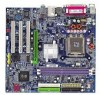
Motherboard Layout COMA LPT KB_MS ATX_12V COMB LGA775 CPU_FAN FDD ATX VGA GA-8S661GXM-775 DDR1 DDR2 USB LAN USB AUDIO F_AUDIO SiS 661GX AGP ICS1883 IT8705AF BIOS CODEC CD_IN SUR_CEN SPDIF_IO IDE2 IDE1 PCI1 CLR_CMOS PCI2 SiS 964 SYS _FAN SATA1 PCI3 BAT F_USB1 F_USB2 CI - Gigabyte GA-8S661GXM-775 | Manual - Page 7
Host Interface 266/333/400MHz DDR RAM SiS 661GX HCLK+/- (133MHz) 3 PCI ICS1883 SiS 964 133MHz 33 MHz 14.318 MHz 48 MHz 2 Serial ATA BIOS LPC BUS IT8705AF Floppy LPT Port AC97 Link PCICLK (33MHz) MIC LINE-IN LINE-OUT RJ45 AC97 CODEC 8 USB ATA33/66/100/ Ports 133 IDE - Gigabyte GA-8S661GXM-775 | Manual - Page 8
- 8 - - Gigabyte GA-8S661GXM-775 | Manual - Page 9
installation, please follow the instructions below: 1. Please turn off the information in the provided manual. 3. Before using the product about any installation steps or have a problem related to the use of the product, the conditions recommended in the user manual. 3. Damage due to improper - Gigabyte GA-8S661GXM-775 | Manual - Page 10
In ; Line Out ; MIC In Š Supports 2 / 4 / 6 channel audio Š SPDIF In/Out connection Š CD In connection Š Supports Jack-Sensing function Š IT8705AF Š CPU / System fan speed detection Š System voltage detection Š CPU temperature detection Š CPU Smart Fan Control GA-8S661GXM-775 Motherboard - 10 - - Gigabyte GA-8S661GXM-775 | Manual - Page 11
data transfer rate of up to 150 MB/s - supports hot plugging function - supports a maximum of 2 SATA connections Use of licensed AWARD BIOS Supports Q-Flash Supports @BIOS Supports EasyTune (only supports Hardware Monitor function) Over Clock via BIOS (CPU/DDR/AGP) Micro-ATX form factor; 24.4cm - Gigabyte GA-8S661GXM-775 | Manual - Page 12
HT Technology - Chipset: An SiS® Chipset that supports HT Technology - BIOS: A BIOS that supports HT Technology and has it enabled - OS: or bending motions that might cause damage to the CPU during installation.) GA-8S661GXM-775 Motherboard - 12 - Fig. 4 Once the CPU is properly inserted, - Gigabyte GA-8S661GXM-775 | Manual - Page 13
pins diagonally. Fig. 4 Please make sure the Male and Female push pin are joined closely. (for detailed installation instructions, please refer to the heatsink installation section of the user manual) Fig. 5 Please check the back of motherboard after installing. If the push pin is inserted as the - Gigabyte GA-8S661GXM-775 | Manual - Page 14
1. Please make sure that the memory used is supported by the motherboard. It is recommended that memory of The motherboard has 2 dual inline memory module (DIMM) sockets. The BIOS will automatically detects memory type and size. To install the memory module, . 2 GA-8S661GXM-775 Motherboard - 14 - - Gigabyte GA-8S661GXM-775 | Manual - Page 15
the steps outlined below: 1. Read the related expansion card's instruction document before installing the expansion card into the computer. 2. Power on the computer, if necessary, setup BIOS utility of expansion card from BIOS. 8. Install related driver from the operating system. Installing a AGP - Gigabyte GA-8S661GXM-775 | Manual - Page 16
USB interface. Also make sure your OS supports USB controller. If your OS does not supportUSB controller, please contact OS vendor for possible patch or driver upgrade. For more information please contact your MIC In Microphone can be connected to MIC In jack. GA-8S661GXM-775 Motherboard - 16 - - Gigabyte GA-8S661GXM-775 | Manual - Page 17
English 1-7 Connectors Introduction 1 3 2 15 10 11 13 12 1) ATX_12V 2) ATX (Power Connector) 3) CPU_FAN 4) SYS_FAN 5) FDD 6) IDE1/IDE2 7) SATA0 / SATA1 8) F_PANEL 9) PWR_LED 5 6 18 17 4 7 8 14 16 9 10) F_AUDIO 11) CD_IN 12) SPDIF_IO 13) SUR_CEN 14) F_USB1 / F_USB2 15) COMB 16) CI 17) CLR_CMOS - Gigabyte GA-8S661GXM-775 | Manual - Page 18
10 +12V 11 3.3V 12 -12V 13 GND 14 PS_ON(soft on/off) 15 GND 16 GND 17 GND 18 -5V 19 +5V 20 +5V GA-8S661GXM-775 Motherboard - 18 - - Gigabyte GA-8S661GXM-775 | Manual - Page 19
connector is used to connect the FDD cable while the other end of the cable connects to the FDD drive. The types of FDD drives supported are: 360KB, 720KB, 1.2MB, 1.44MB and 2.88MB. Please connect the red power connector wire to the pin1 position. 34 33 2 1 - 19 - Hardware Installation - Gigabyte GA-8S661GXM-775 | Manual - Page 20
Slave (for information on settings, please refer to the instructions located on the IDE device). 40 39 40 39 BIOS setting for the Serial ATA and install the proper driver in order to work properly. Pin No. Definition 1 GND 1 7 2 TXP 3 TXN 4 GND 5 RXN 6 RXP 7 GND GA-8S661GXM-775 - Gigabyte GA-8S661GXM-775 | Manual - Page 21
English 8) F_PANEL (Front Panel Connector) Please connect the power LED, PC speaker, reset switch and power switch etc. of your chassis front panel to the F_PANEL connector according to the pin assignments below. Message LED/ Power/ Sleep LED Speaker Connector Power Switch MSG+ MSG- PW+ PWSPEAK+ - Gigabyte GA-8S661GXM-775 | Manual - Page 22
use "Front Audio" connector, you must remove the jumpers from pins 5-6, 9-10. Pin No. Definition 10 9 1 MIC 2 GND 2 1 3 MIC_BIAS 4 POWER 5 FrontAudio(R) 6 Rear Audio (R)/ Return R 7 NC 8 No Pin 9 FrontAudio (L) 10 Rear Audio (L)/ Return L GA-8S661GXM-775 Motherboard - 22 - Gigabyte GA-8S661GXM-775 | Manual - Page 23
to the connector. 1 Pin No. Definition 1 CD-L 2 GND 3 GND 4 CD-R 12) SPDIF_IO (SPDIF In/ Out) The SPDIF output is capable of providing digital audio to external speakers or compressed AC3 data to an external Dolby Digital Decoder. Use this feature only when your stereo system has digital - Gigabyte GA-8S661GXM-775 | Manual - Page 24
USB cable, please contact your local dealer. 2 10 1 9 Pin No. 1 2 3 4 5 6 7 8 9 10 Definition Power Power USB0 DXUSB1 DyUSB0 DX+ USB1 Dy+ GND GND No Pin NC GA-8S661GXM-775 Motherboard - 24 - - Gigabyte GA-8S661GXM-775 | Manual - Page 25
Intrusion, Case Open) This 2-pin connector allows your system to detect if the chassis cover is removed. You can check the "Case Opened" status in BIOS Setup. Pin No. Definition 1 1 Signal 2 GND - 25 - Hardware Installation - Gigabyte GA-8S661GXM-775 | Manual - Page 26
Short: Clear CMOS 18) BAT (Battery) GA-8S661GXM-775 Motherboard Danger of explosion if battery is incorrectly replaced. Replace only with the same or equivalent type recommended by the manufacturer. Dispose of used batteries according to the manufacturer's instructions. If you want to erase CMOS - Gigabyte GA-8S661GXM-775 | Manual - Page 27
- 27 - Hardware Installation English - Gigabyte GA-8S661GXM-775 | Manual - Page 28
English GA-8S661GXM-775 Motherboard - 28 - - Gigabyte GA-8S661GXM-775 | Manual - Page 29
a new BIOS, either Gigabyte's Q-Flash or @BIOS utility can be used. Q-Flash allows the user to quickly and easily update or backup BIOS without entering the operating system. @BIOS is a Windows-based utility that does not require users to boot to DOS before upgrading BIOS but directly download and - Gigabyte GA-8S661GXM-775 | Manual - Page 30
„ Standard CMOS Features This setup page includes all the items in standard compatible BIOS. „ Advanced BIOS Features This setup page includes all the items of Award special enhanced features. „ with which the system would be in best performance configuration. GA-8S661GXM-775 Motherboard - 30 - - Gigabyte GA-8S661GXM-775 | Manual - Page 31
system. „ Save & Exit Setup Save CMOS value settings to CMOS and exit setup. „ Exit Without Saving Abandon all CMOS value changes and exit setup. - 31 - BIOS Setup - Gigabyte GA-8S661GXM-775 | Manual - Page 32
` IDE Channel 1 Slave Drive A Drive B Floppy 3 Mode Support [None] [None] [None] [None] [1.44M, 3.5"] [None from Sun. to Sat., is determined by the BIOS and displayed only. Month The month, from Jan system start up. Manual User can manually input the correct GA-8S661GXM-775 Motherboard - 32 - - Gigabyte GA-8S661GXM-775 | Manual - Page 33
Default value) 3.5 inch double-sided drive; 2.88M byte capacity. Floppy 3 Mode Support (for Japan Area) Disabled Drive A Drive B Normal Floppy Drive. (Default may be detected and you will be prompted. All Errors Whenever the BIOS detects a non-fatal error the system will be stopped. All, But - Gigabyte GA-8S661GXM-775 | Manual - Page 34
Utility-Copyright (C) 1984-2005 Award Software Advanced BIOS Features ` Hard Disk Boot Priority First Boot 1: This option is available only when the processor you install supports Intel® HyperThreading Technology. Note 2: This option is available only function. GA-8S661GXM-775 Motherboard - 34 - - Gigabyte GA-8S661GXM-775 | Manual - Page 35
1.2M and 1.44M are all 80 tracks. Disabled BIOS will not search for the type of floppy disk drive only when the processor you install supports Intel® Hyper-Threading Technology. Enabled OS like NT4. Disabled Disable CPUID Limit for Windows XP. (Defaults value) Init Display First Select the - Gigabyte GA-8S661GXM-775 | Manual - Page 36
AC97 Audio Onboard LAN device USB Controller USB Legacy Support SiS compatible with ATA33) IDE2 Conductor Cable Auto BIOS autodetects IDE2 conductor cable. (Default Value) ATA66 Audio Enabled Disabled Autodetect AC97 audio function. (Default value) Disable AC97 audio function. GA-8S661GXM-775 - Gigabyte GA-8S661GXM-775 | Manual - Page 37
USB Controller. USB Legacy Support Enabled Disabled Enable USB Legacy Support. Disable USB Legacy Support. (Default value) Serial ATA Mode to RAID. (Default value) Onboard Serial Port 1 Auto 3F8/IRQ4 BIOS will automatically setup the Serial port 1 address. Enable onboard Serial port 1 and - Gigabyte GA-8S661GXM-775 | Manual - Page 38
Don't monitor IRQ [3-7, 9-15] or NMI. Enabled Monitor IRQ [3-7, 9-15] or NMI. (Default value) ModemRingOn Disabled Enabled Disable ModemRingOn function. (Default value) Enable ModemRingOn function. GA-8S661GXM-775 Motherboard - 38 - - Gigabyte GA-8S661GXM-775 | Manual - Page 39
Blinking The Power LED will be blinking during S1 state. (Default value) Dual/OFF The Power LED will be turned off or change color. - 39 - BIOS Setup - Gigabyte GA-8S661GXM-775 | Manual - Page 40
) Set IRQ 3,4,5,7,9,10,11,12,14,15 to PCI 2. Auto assign IRQ to PCI 3. (Default value) Set IRQ 3,4,5,7,9,10,11,12,14,15 to PCI 3. GA-8S661GXM-775 Motherboard - 40 - - Gigabyte GA-8S661GXM-775 | Manual - Page 41
temperature. c. When the CPU temperature is lower than 20 degrees Celsius, CPU fan will stop spinning. Disabled Disable the CPU Smart FAN Control function. - 41 - BIOS Setup - Gigabyte GA-8S661GXM-775 | Manual - Page 42
BIOS will automatically set up the DRAM Timing by DRAM SPD data. Manual (Default value) This item allows user to set DRAM Timing manually. CAS Latency Setting 2T/2.5T/3T Set CAS Latency to 2T/2.5T/3T. (Default value: 2.5T) Auto BIOS will automatically detect CAS Latency. GA-8S661GXM-775 - Gigabyte GA-8S661GXM-775 | Manual - Page 43
MHz) This option is available only when AGP/PCI Clock Control is set to Manual. Please set AGP Clock according to your requirement. Incorrect using it may cause your AGP Clock (MHz) manually, the PCI Clock (MHz) will change automatically depending on the AGP Clock (MHz) you set. - 43 - BIOS Setup - Gigabyte GA-8S661GXM-775 | Manual - Page 44
Standard CMOS Features Load Fail-Safe Defaults ` Advanced BIOS Features Load Optimized Defaults ` Integrated Peripherals Set Supervisor Selecting this field loads the factory defaults for BIOS and Chipset Features which the system automatically detects. GA-8S661GXM-775 Motherboard - 44 - - Gigabyte GA-8S661GXM-775 | Manual - Page 45
the system will boot and you can enter Setup freely. The BIOS Setup program allows you to specify two separate passwords: SUPERVISOR PASSWORD and only basic items. If you select "System" at "Password Check" in Advance BIOS Features Menu, you will be prompted for the password every time the system is - Gigabyte GA-8S661GXM-775 | Manual - Page 46
-2005 Award Software ` Standard CMOS Features Load Fail-Safe Defaults ` Advanced BIOS Features Load Optimized Defaults ` Integrated Peripherals Set Supervisor Password ` Power Management without saving to RTC CMOS. Type "N" will return to Setup Utility. GA-8S661GXM-775 Motherboard - 46 - - Gigabyte GA-8S661GXM-775 | Manual - Page 47
- 47 - BIOS Setup English - Gigabyte GA-8S661GXM-775 | Manual - Page 48
English GA-8S661GXM-775 Motherboard - 48 - - Gigabyte GA-8S661GXM-775 | Manual - Page 49
, afterward you can install others applications. Click "GO". For USB2.0 driver support under Windows XP operating system, please use Windows Service Pack. After install Windows Service Pack, it will show a question mark "?" in "Universal Serial Bus controller" under "Device Manager". Please remove - Gigabyte GA-8S661GXM-775 | Manual - Page 50
English 3-2 Software Applications This page displays all the tools that Gigabyte developed and some free software. You can click an item to install it. 3-3 Driver CD Information This page lists the contents of software and drivers in this CD-title. GA-8S661GXM-775 Motherboard - 50 - - Gigabyte GA-8S661GXM-775 | Manual - Page 51
English 3-4 Hardware Information This page lists all device you have for this motherboard. 3-5 Contact Us You can also see the last page of this manual for contacts information details. - 51 - Drivers Installation - Gigabyte GA-8S661GXM-775 | Manual - Page 52
English GA-8S661GXM-775 Motherboard - 52 - - Gigabyte GA-8S661GXM-775 | Manual - Page 53
EasyTune 5 Introduction EasyTune 5 presents the most convenient Windows based system performance enhancement and manageability utility. Featuring panel of CPU frequency Shows the current functions status Log on to GIGABYTE website Display EasyTuneTM 5 Help file Quit or Minimize EasyTuneTM 5 soft- - Gigabyte GA-8S661GXM-775 | Manual - Page 54
of hard disk data. Supporting Microsoft operating systems including Windows XP/2000/NT/98/Me and BIOS Setup, go to Advanced BIOS Feature and set to boot from CD-ROM. Save the settings and exit the BIOS Setup. Insert the provided driver drivers as well as software. GA-8S661GXM-775 Motherboard - 54 - - Gigabyte GA-8S661GXM-775 | Manual - Page 55
supports only PATA hard disks and not SATA hard disks on the following motherboards (As this is a BIOS-related issue, it can be solved by BIOS update) GA-K8U GA-K8U-9 GA-K8NXP-SLI GA-K8N Ultra-SLI GA-K8N Pro-SLI GA-K8NXP-9 GA-K8N Ultra-9 GA-K8NF-9 (PCB Ver. 1.0) GA-K8NE (PCB Ver. 1.0) GA - Gigabyte GA-8S661GXM-775 | Manual - Page 56
Primary Master : FUJITSU MPE3170AT ED-03-08 Primary Slave : None Secondary Master : CREATIVEDVD-RM DVD1242E BC101 Secondary Slave : None Press DEL to enter SETUP / Dual BIOS / Q-Flash / F9 For Xpress Recovery 08/07/2003-i875P-6A79BG03C-00 GA-8S661GXM-775 Motherboard - 56 - - Gigabyte GA-8S661GXM-775 | Manual - Page 57
Load Fail-Safe Defaults Load Optimized Defaults Set Supervisor Password Set User Password Save & Exit Setup Exit Without Saving ESC: Quit F8: Dual BIOS/Q-Flash F3: Change Language F10: Save & Exit Setup Time, Date, Hard Disk Type... Step 2: Press F8 button on your keyboard and then Y button - Gigabyte GA-8S661GXM-775 | Manual - Page 58
from Floppy Save Main BIOS to Floppy Save Backup BIOS to Floppy Enter : Run :Move ESC:Reset F10:Power Off Do not turn off power or reset your system at this stage!! After BIOS file is read, you'll see a dialog box asking you "Are you sure to update BIOS?" GA-8S661GXM-775 Motherboard - 58 - - Gigabyte GA-8S661GXM-775 | Manual - Page 59
too. 5. Press Esc and then Y button to exit the Q-Flash utility. The computer will restart automatically after you exit Q-Flash. Dual BIOS Utility Boot From Main Bios Main ROM Type/Size SST 49LF004A Backup ROM Type/Size SST 49LF004A 512K 512K Wide Range Protection Disable Boot From Main - Gigabyte GA-8S661GXM-775 | Manual - Page 60
and exit. Part Two: Updating BIOS with Q-FlashTM Utility on Single-BIOS Motherboards. This part guides users of single-BIOS motherboards how to update BIOS using the Q-FlashTM utility. CMOS Change Language F10: Save & Exit Setup Time, Date, Hard Disk Type... GA-8S661GXM-775 Motherboard - 60 - - Gigabyte GA-8S661GXM-775 | Manual - Page 61
file you want to flash and press Enter. In this example, we only download one BIOS file to the floppy disk so only one BIOS file, 8GE800.F4, is listed. Please confirm again you have the correct BIOS file for your motherboard. Q-Flash Utility V1.30 Flash Type/Size SST 49LF002A 256K 8GE800.F4Keep - Gigabyte GA-8S661GXM-775 | Manual - Page 62
03/18/2003-I845GE-6A69YG01C-00 6. Press Del to enter BIOS menu after system reboots and "Load BIOS Fail-Safe Defaults". See how to Load BIOS Fail-Safe Defaults, please kindly refer to Step 6 to 7 in Part One. Congratulation!! You have updated BIOS successfully!! GA-8S661GXM-775 Motherboard - 62 - - Gigabyte GA-8S661GXM-775 | Manual - Page 63
Update New BIOS c. Please select "All Files" in dialog box while opening the downloaded BIOS file. d. Please search for BIOS unzip file, downloading from the Internet or any other methods (such as: 8S661GXM-775.F1). e. Complete update process following the on-screen instructions. - 63 - Appendix - Gigabyte GA-8S661GXM-775 | Manual - Page 64
won't boot. III. In method I, if the BIOS file you need cannot be found in @BIOSTM server, please go onto Gigabyte's web site for downloading and updating it according to method II. IV. Please note that any interruption during updating will cause system unbooted. GA-8S661GXM-775 Motherboard - 64 - - Gigabyte GA-8S661GXM-775 | Manual - Page 65
English 4-1-4 Serial ATA BIOS Setting Utility Introduction RAID Levels RAID (Redundant Array of of the smallest member. The striping block size can be set from 16KB to 256KB. RAID 0 does not support fault tolerance. RAID 1 (Mirroring) RAID 1 writes duplicate data onto a pair of drives and reads both - Gigabyte GA-8S661GXM-775 | Manual - Page 66
Status window appears (refer to Figure 2). To create RAID, press to enter the RAID Setup utility. SiS RAID BIOS Setting Utility * Current Created Raid * Disk Status [R] : Enter Raid setup utility [Q] : Exit current menu Location Model Disk 1 Disk 2 ST3120026AS ST3120026AS GA-8S661GXM-775 - Gigabyte GA-8S661GXM-775 | Manual - Page 67
English Creating RAID Volume Step 1: In the RAID Setup window, press to create RAID volume (Figure 3). SiS RAID BIOS Setting Utility * Current Created Raid * RAID Setup Press [A] key to create RAID [Q] : Exit current menu Location Model Disk 1 Disk 2 ST3120026AS ST3120026AS Capacity - Gigabyte GA-8S661GXM-775 | Manual - Page 68
BIOS Setting Utility * Current Created Raid * RAID Setup RAID 0 Split the SOURCE (Disk 1) data to RAID disks? N [Q] : Exit current menu Location Model Disk 1 Disk 2 ST3120026AS ST3120026AS Capacity 111GB 111GB Mode UDMA 6 UDMA 6 RAID Type RAID0 RAID0 Figure 6 GA-8S661GXM-775 Motherboard - Gigabyte GA-8S661GXM-775 | Manual - Page 69
English After the completion, you will see the RAID array under the * Current Created Raid * list in the RAID Setup window (Figure 7). SiS RAID BIOS Setting Utility * Current Created Raid * RAID 0 : Disk 1 Disk 2 RAID Setup Press [D] key to delete RAID [Q] : Exit current menu Location Model - Gigabyte GA-8S661GXM-775 | Manual - Page 70
following window BIOS Setting Utility * Current Created Raid * RAID 0 : Disk 1 Disk 2 RAID Setup Press [D] key to delete RAID [Q] : Exit current menu Location Model Disk 1 Disk 2 ST3120026AS ST3120026AS Capacity 111GB 111GB Mode UDMA 6 UDMA 6 RAID Type RAID0 RAID0 Figure 9 GA-8S661GXM-775 - Gigabyte GA-8S661GXM-775 | Manual - Page 71
recognized during the Windows setup process. First of all, copy the driver for the SATA controller from the motherboard driver CD-ROM to a floppy disk. See the instructions below about how to copy the driver in MS-DOS mode(Note1). Prepare a startup disk that has CD-ROM support and a blank formatted - Gigabyte GA-8S661GXM-775 | Manual - Page 72
the audio driver, you'll find a Sound Effect icon on the lower right hand taskbar. Click the icon to select the function. STEP 3: On the AC97 Audio Configuration menu, click the Speaker Configuration tab and select the 2-channel mode for stereo speaker output check box. GA-8S661GXM-775 Motherboard - Gigabyte GA-8S661GXM-775 | Manual - Page 73
Out," the rear channels to "Line In." STEP 2: After installing the audio driver, you'll find a Sound Effect icon on the lower right hand taskbar. Click the icon to select the function. STEP 3: On the AC97 Audio Configuration menu, click the Speaker Configuration tab and select the 4-channel mode - Gigabyte GA-8S661GXM-775 | Manual - Page 74
In". MIC In Line Out STEP 2: After installing the audio driver, you'll find a Sound Effect icon on the Audio Configuration menu, click the Speaker Configuration tab and select the 6-channel mode for 5.1 speaker output check box. Clear the Only SURROUND-KIT check box and press OK. GA-8S661GXM-775 - Gigabyte GA-8S661GXM-775 | Manual - Page 75
. It is the best solution if you need 6 channel output, Line In and MIC at the same time. "SURROUND-KIT" is included in the GIGABYTE unique "Audio Combo Kit" as picture. STEP 1: Secure the metal bracket of the"Surround Kit" to the chassis back panel with a screw. STEP 2: Connect the "SURROUND - Gigabyte GA-8S661GXM-775 | Manual - Page 76
-KIT's SUB CENTER. STEP 4: After installing the audio driver, you'll find a Sound Effect icon on the Audio Output Mode Notes: When the Environment setting is None, the sound would be performed as stereo mode (2-channel output). Please select the other settings for 6 channels output. GA-8S661GXM-775 - Gigabyte GA-8S661GXM-775 | Manual - Page 77
SPDIF Output Device (Optional Device) A "SPDIF output" device is an optional device. The SPDIF_IO cable with rear bracket could link to the "SPDIF_IO" connector (As picture.) For the further linkage to decoder, rear bracket provides coaxial cable and Fiber connecting port. STEP 1: Secure the metal - Gigabyte GA-8S661GXM-775 | Manual - Page 78
Out jack, and microphone to MIC In jack. Auto-detecting: Please connect the devices to the right jacks as above. A window will appear as right picture if you setup the devices properly. Please note that 3D audio function will only appear when 3D audio inputs. GA-8S661GXM-775 Motherboard - 78 - - Gigabyte GA-8S661GXM-775 | Manual - Page 79
English If you set wrong with the connectors, the warning message will come out as right picture. Manual setting: If the device picture shows different from what you set, please press "Manual Selection" to set. - 79 - Appendix - Gigabyte GA-8S661GXM-775 | Manual - Page 80
/write failure 9 beeps ROM checksum error 10 beeps CMOS shutdown register read/write error 11 beeps Cache memory bad GA-8S661GXM-775 Motherboard - 80 - AWARD BIOS Beep Codes 1 short: System boots successfully 2 short: CMOS setting error 1 long 1 short: DRAM or M/B error 1 long 2 short: Monitor or - Gigabyte GA-8S661GXM-775 | Manual - Page 81
- 81 - Appendix English - Gigabyte GA-8S661GXM-775 | Manual - Page 82
English GA-8S661GXM-775 Motherboard - 82 - - Gigabyte GA-8S661GXM-775 | Manual - Page 83
- 83 - Appendix English - Gigabyte GA-8S661GXM-775 | Manual - Page 84
English GA-8S661GXM-775 Motherboard - 84 - - Gigabyte GA-8S661GXM-775 | Manual - Page 85
- 85 - Appendix English - Gigabyte GA-8S661GXM-775 | Manual - Page 86
English GA-8S661GXM-775 Motherboard - 86 - - Gigabyte GA-8S661GXM-775 | Manual - Page 87
.giga-byte.com U.S.A. G.B.T. INC. TEL: +1-626-854-9338 FAX: +1-626-854-9339 Tech. Support : http://tw.giga-byte.com/TechSupport/ServiceCenter.htm Non-Tech. Support(Sales/Marketing) : http://ggts.gigabyte.com.tw/nontech.asp WEB address : http://www.giga-byte.com Germany G.B.T. TECHNOLOGY TRADING GMBH - Gigabyte GA-8S661GXM-775 | Manual - Page 88
://www.gigabyte.cz Romania Representative Office Of GIGA-BYTE Technology Co., Ltd. in Romania Tech. Support : http://tw.giga-byte.com/TechSupport/ServiceCenter.htm Non-Tech. Support(Sales/Marketing) : http://ggts.gigabyte.com.tw/nontech.asp WEB address: http://www.gigabyte.com.ro GA-8S661GXM-775
-
 1
1 -
 2
2 -
 3
3 -
 4
4 -
 5
5 -
 6
6 -
 7
7 -
8
-
9
-
10
-
11
-
12
-
13
-
14
-
15
-
16
-
17
-
18
-
19
-
20
-
21
-
22
-
23
-
24
-
25
-
26
-
27
-
28
-
29
-
30
-
31
-
32
-
33
-
34
-
35
-
36
-
37
-
38
-
39
-
40
-
41
-
42
-
43
-
44
-
45
-
46
-
47
-
48
-
49
-
50
-
51
-
52
-
53
-
54
-
55
-
56
-
57
-
58
-
59
-
60
-
61
-
62
-
63
-
64
-
65
-
66
-
67
-
68
-
69
-
70
-
71
-
72
-
73
-
74
-
75
-
76
-
77
-
78
-
79
-
80
-
81
-
82
-
83
-
84
-
85
-
86
-
87
-
88
 |
 |

GA-8S661GXM-775
Intel
®
Pentium
®
4
LGA775 Processor Motherboard
User's Manual
Rev. 1002
12ME-S661GXMT-1002
*
The WEEE marking on the product indicates this product must not be disposed of with user's other household waste
and must be handed over to a designated collection point for the recycling of waste electrical and electronic equipment!!
*
The WEEE marking applies only in European Union's member states.