Gigabyte GA-8VM800M-775 Manual
Gigabyte GA-8VM800M-775 Manual
 |
View all Gigabyte GA-8VM800M-775 manuals
Add to My Manuals
Save this manual to your list of manuals |
Gigabyte GA-8VM800M-775 manual content summary:
- Gigabyte GA-8VM800M-775 | Manual - Page 1
GA-8VM800M-775 Intel® Pentium® 4 LGA775 Processor Motherboard User's Manual Rev. 1002 12ME-VM800MT-1002R * The WEEE marking on the product indicates this product must not be disposed of with user's other household waste and must be handed over to a designated collection point for the recycling of - Gigabyte GA-8VM800M-775 | Manual - Page 2
Motherboard GA-8VM800M-775 Aug. 18, 2005 Motherboard GA-8VM800M-775 Aug. 18, 2005 - Gigabyte GA-8VM800M-775 | Manual - Page 3
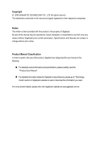
following: „ For detailed product information and specifications, please carefully read the "Product User Manual". „ For detailed information related to Gigabyte's unique features, please go to "Technology Guide" section on Gigabyte's website to read or download the information you need. For more - Gigabyte GA-8VM800M-775 | Manual - Page 4
Table of Contents GA-8VM800M-775 Motherboard Layout 6 Block Diagram ...7 Chapter 1 Hardware Installation 9 1-1 Considerations Prior to Installation 9 1-2 Feature Summary 10 1-3 Installation of the CPU and Heatsink 12 1-3-1 Installation of the CPU 12 1-3-2 Installation of the Heatsink 13 1-4 - Gigabyte GA-8VM800M-775 | Manual - Page 5
53 4-1 Unique Software Utilities 53 4-1-1 EasyTune 5 Introduction 54 4-1-2 Xpress Recovery2 Introduction 55 4-1-3 Flash BIOS Method Introduction 57 4-1-4 Serial ATA BIOS Setting Utility Introduction 66 4-1-5 2 / 4 / 6 Channel Audio Function Introduction 73 4-2 Troubleshooting 79 - 5 - - Gigabyte GA-8VM800M-775 | Manual - Page 6
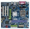
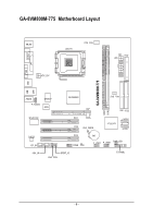
GA-8VM800M-775 Motherboard Layout VGA COMA LPT KB_MS LGA775 CPU_FAN ATX_12V FDD ATX GA-8VM800M-775 DDR1 DDR2 USB LAN USB AUDIO F_AUDIO W83627 BIOS VIA P4M800 AGP SYS _FAN IDE1 IDE2 RTL8100C PCI1 PCI2 CLR_CMOS VT8237R SATA1 SATA0 CODEC CD_IN PCI3 COMB CI BAT F_USB1 F_USB2 PWR_LED - Gigabyte GA-8VM800M-775 | Manual - Page 7
Diagram LGA 775 Processor CPUCLK+/- (133/200MHz) AGP 4X/8X AGPCLK (66MHz) VGA Port 3 PCI RJ45 RTL8100C 66MHz V_Link System Bus 533/800MHz 266/333/400MHz VIA P4M800 DDR HCLK (200/133MHz) GCLKNB 66MHz 33MHz 48MHz 14.318MHz VIA VT8237R 2 Serial ATA LPC BUS Winbond W83627 BIOS Floppy LPT - Gigabyte GA-8VM800M-775 | Manual - Page 8
- 8 - - Gigabyte GA-8VM800M-775 | Manual - Page 9
off the computer and unplug its power cord. 2. When handling the motherboard, avoid touching any metal leads or connectors. 3. It is best to wear an electrostatic discharge (ESD) cuff when handling electronic components (CPU, RAM). 4. Prior to installing the electronic components, please have these - Gigabyte GA-8VM800M-775 | Manual - Page 10
English 1-2 Feature Summary CPU Chipset Memory Slots IDE Connections Onboard SATA FDD Connections Peripherals Onboard VGA Onboard LAN Onboard Audio I/O Control Hardware Monitor Š Supports the latest Intel® Pentium® 4 LGA775 CPU Š Supports 533/800MHz FSB Š L2 cache varies with processors Š - Gigabyte GA-8VM800M-775 | Manual - Page 11
150 MB/sec Up to 2 SATA Device Use of licensed AWARD BIOS Supports Q-Flash Supports @BIOS Supports EasyTune (Note 2) Over Clock via BIOS (CPU/DRAM) Over Voltage via BIOS (AGP/DIMM) Micro-ATX form factor; 24.4cm x 23.3cm (Note 2) EasyTune functions may vary depending on different motherboards. - 11 - Gigabyte GA-8VM800M-775 | Manual - Page 12
- CPU: An Intel® Pentium 4 Processor with HT Technology - Chipset: An VIA Chipset that supports HT Technology - BIOS: A BIOS that supports HT that might cause damage to the CPU during installation.) GA-8VM800M-775 Motherboard - 12 - Fig. 4 Once the CPU is properly inserted, please replace the - Gigabyte GA-8VM800M-775 | Manual - Page 13
the CPU and make sure the push pins aim to the pin hole on the motherboard.Pressing down the push pins diagonally. Fig. 4 Please make sure the Male and Female push pin are joined closely. (for detailed installation instructions, please refer to the heatsink installation section of the user manual - Gigabyte GA-8VM800M-775 | Manual - Page 14
DIMM memory module vertically into the DIMM socket. Then push it down. DDR memory module Fig.2 Close the plastic clip at both edges of the DIMM sockets to lock the DIMM module. Reverse the installation steps when you wish to remove the DIMM module. Fig. 1 Fig. 2 GA-8VM800M-775 Motherboard - 14 - Gigabyte GA-8VM800M-775 | Manual - Page 15
instruction into expansion slot in motherboard. 4. Be sure BIOS. 8. Install related driver from the operating system. Installing a AGP expansion card: Please carefully pull out the small whitedrawable bar at the end of the AGP slot when you try to install/uninstall the VGA card. Please align the VGA - Gigabyte GA-8VM800M-775 | Manual - Page 16
Serial port. VGA Port Monitor can be connected to VGA port. USB supports USB controller. If your OS does not supportUSB controller, please contact OS vendor for possible patch or driver upgrade. For more information please contact your OS or device(s) vendors. LAN GA-8VM800M-775 Motherboard - 16 - - Gigabyte GA-8VM800M-775 | Manual - Page 17
English 1-7 Connectors Introduction 3 2 5 1 6 4 10 7 19 9 11 8 12 14 13 16 17 18 15 1) ATX_12V 2) ATX (Power Connector) 3) CPU_FAN 4) SYS_FAN 5) FDD 6) IDE1/IDE2 7) SATA0 / SATA1 8) F_PANEL 9) PWR_LED 10) F_AUDIO 11) CD_IN 12) AUX_IN 13) SPDIF_IO 14) SUR_CEN 15) F_USB1 / F_USB2 16) COMB - Gigabyte GA-8VM800M-775 | Manual - Page 18
Align the power connector with its proper location on the motherboard and connect tightly. The ATX_12V power connector mainly supplies power to the CPU. If the ATX_12V power connector is not connected, the ) 15 GND 16 GND 17 GND 18 -5V 19 +5V 20 +5V GA-8VM800M-775 Motherboard - 18 - - Gigabyte GA-8VM800M-775 | Manual - Page 19
CPU overheating and failure. 1 CPU_FAN 1 SYS_FAN Pin No. 1 2 3 4 Definition GND +12V Sense Speed Control (Only for CPU_FAN) 5) FDD (FDD Connector) The FDD connector is used to connect the FDD cable while the other end of the cable connects to the FDD drive. The types of FDD drives supported - Gigabyte GA-8VM800M-775 | Manual - Page 20
for information on settings, please refer to the instructions located on the IDE device). 40 39 40 BIOS setting for the Serial ATA and install the proper driver in order to work properly. Pin No. Definition 1 GND 1 7 2 TXP 3 TXN 4 GND 5 RXN 6 RXP 7 GND GA-8VM800M-775 Motherboard - Gigabyte GA-8VM800M-775 | Manual - Page 21
English 8) F_PANEL (Front Panel Connector) Please connect the power LED, PC speaker, reset switch and power switch etc. of your chassis front panel to the F_PANEL connector according to the pin assignments below. Message LED/ Power/ Sleep LED Speaker Connector Power Switch MSG+ MSG- PW+ PWSPEAK+ - Gigabyte GA-8VM800M-775 | Manual - Page 22
use "Front Audio" connector, you must remove the jumpers from pins 5-6, 9-10. Pin No. Definition 10 9 1 MIC 2 GND 2 1 3 MIC_BIAS 4 POWER 5 FrontAudio(R) 6 Rear Audio (R)/ Return R 7 NC 8 No Pin 9 FrontAudio (L) 10 Rear Audio (L)/ Return L GA-8VM800M-775 Motherboard - 22 - - Gigabyte GA-8VM800M-775 | Manual - Page 23
11) CD_IN (CD IN Connector) Connect CD-ROM or DVD-ROM audio out to the connector. 1 Pin No. Definition 1 CD-L 2 GND 3 GND 4 CD-R 12) AUX_IN (AUX In Connector) Connect other device (such as PCI TV Tunner audio out) to the connector. 1 Pin No. Definition 1 AUX-L 2 GND 3 GND 4 AUX - Gigabyte GA-8VM800M-775 | Manual - Page 24
13) SPDIF_IO (SPDIF In/ Out) The SPDIF output is capable of providing digital audio to external speakers or compressed AC3 data to an external Dolby Digital Decoder. Use this . 26 15 Pin No. 1 2 3 4 5 6 Definition SUR OUTL SUR OUTR GND No Pin CENTER_OUT BASS_OUT GA-8VM800M-775 Motherboard - 24 - - Gigabyte GA-8VM800M-775 | Manual - Page 25
English 15) F1_USB / F2_USB (Front USB Connectors) Be careful with the polarity of the front USB connector. Check the pin assignment carefully while you connect the front USB cable, incorrect connection between the cable and connector will make the device unable to work or even damage it. For - Gigabyte GA-8VM800M-775 | Manual - Page 26
your system to detect if the chassis cover is removed. You can check the "Case Opened" status in BIOS Setup. Pin No. Definition 1 1 GND 2 Signal 18) CLR_CMOS (Clear CMOS) You may clear the not include a jumper on it. 1 Open: Normal 1 Short: Clear CMOS GA-8VM800M-775 Motherboard - 26 - - Gigabyte GA-8VM800M-775 | Manual - Page 27
is incorrectly replaced. Replace only with the same or equivalent type recommended by the manufacturer. Dispose of used batteries according to the manufacturer's instructions. If you want to erase CMOS... 1. Turn OFF the computer and unplug the power cord. 2. Take out the battery gently and put it - Gigabyte GA-8VM800M-775 | Manual - Page 28
English GA-8VM800M-775 Motherboard - 28 - - Gigabyte GA-8VM800M-775 | Manual - Page 29
BIOS, either GIGABYTE's Q-Flash or @BIOS utility can be used. Q-Flash allows the user to quickly and easily update or backup BIOS without entering the operating system. @BIOS is a Windows-based utility that does not require users to boot to DOS before upgrading BIOS but directly download and update - Gigabyte GA-8VM800M-775 | Manual - Page 30
motherboard. The Main Menu (For example: BIOS Ver. : E12) Once you enter Award BIOS Set User Password CPU's clock and frequency ratio. „ Load Fail-Safe Defaults Fail-Safe Defaults indicates the value of the system parameters which the system would be in safe configuration. GA-8VM800M-775 Motherboard - Gigabyte GA-8VM800M-775 | Manual - Page 31
. „ Set Supervisor Password Change, set, or disable password. It allows you to limit access to the system and Setup, or just to Setup. „ Set User Password Change, set, or disable password. It allows you to limit access to the system. „ Save & Exit Setup Save CMOS value settings to CMOS and - Gigabyte GA-8VM800M-775 | Manual - Page 32
Memory Extended Memory Total Memory BIOS to automatically detect IDE devices during POST.(default) None Select this if no IDE devices are used and the system will skip the automatic detection step and allow for faster system start up. Manual User can manually GA-8VM800M-775 Motherboard - 32 - - Gigabyte GA-8VM800M-775 | Manual - Page 33
. Floppy 3 Mode Support (for Japan Area) memory installed on the motherboard. Extended Memory The BIOS determines how much extended memory is present during the POST. This is the amount of memory located above 1 MB in the CPU's memory address map. Total Memory This item displays the memory - Gigabyte GA-8VM800M-775 | Manual - Page 34
BIOS Features ` Hard Disk Boot Priority First Boot Device Second Boot Device Third Boot Device Password Check # CPU Hyper-Threading Limit CPUID Max. to 3 No-Execute Memory Protect (Note) CPU Enhanced Halt (C1E) (Note) CPU SCSI, RAID, etc. supports this function. GA-8VM800M-775 Motherboard - 34 - - Gigabyte GA-8VM800M-775 | Manual - Page 35
system with multi processors mode supported. (Default value) Disables CPU Hyper Threading. Limit CPUID Max. to 3 Enabled Disabled Limit CPUID Maximum value to 3 when use older OS like NT4. Disables CPUID Limit for windows XP. (Default value) No-Execute Memory Protect (Note) Enabled Enables No - Gigabyte GA-8VM800M-775 | Manual - Page 36
ATA SATA Mode AC97 Audio USB 1.1 Controller USB 2.0 Controller USB Keyboard Support USB Mouse Support Onboard H/W LAN OnBoard LAN Boot ROM Onboard USB Keyboard Support Enabled Enable USB keyboard support. Disabled Disable USB keyboard support. (Default value) GA-8VM800M-775 Motherboard - 36 - Gigabyte GA-8VM800M-775 | Manual - Page 37
Support Enabled Enable USB mouse support. Disabled Disable USB mouse support. (Default value) Onboard H/W LAN Enabled Enable onboard LAN chip function. (Default value) Disabled Disable onboard LAN chip function. OnBoard LAN Serial Port 2 Auto 3F8/IRQ4 BIOS will automatically set up the - Gigabyte GA-8VM800M-775 | Manual - Page 38
(Default value) Set ACPI suspend type to S3/STR(Suspend To RAM). USB Device Wake-Up From S3 Disabled Disable USB Device Wake- suspend if button is pressed less than 4 sec. AC BACK Function Memory When AC-power back to the system, the system will be back to GA-8VM800M-775 Motherboard - 38 - - Gigabyte GA-8VM800M-775 | Manual - Page 39
to POWER ON system. If Resume by Alarm is Enabled. Date (of Month) Alarm : Everyday, 1~31 Time (hh: mm: ss) Alarm: (0~23) : (0~59) : (0~59) - 39 - BIOS Setup - Gigabyte GA-8VM800M-775 | Manual - Page 40
) Set IRQ 3,4,5,7,9,10,11,12,14,15 to PCI 2. Auto assign IRQ to PCI 3. (Default value) Set IRQ 3,4,5,7,9,10,11,12,14,15 to PCI 3. GA-8VM800M-775 Motherboard - 40 - - Gigabyte GA-8VM800M-775 | Manual - Page 41
Temp. 60oC / 140oF 70oC / 158oF 80oC / 176oF Monitor CPU temperature at 60oC / 140oF. Monitor CPU temperature at 70oC / 158oF. Monitor CPU temperature at 80oC / 176oF. 90oC / 194oF Monitor CPU temperature at 90oC / 194oF. Disabled Disable this function. (Default value) - 41 - BIOS Setup - Gigabyte GA-8VM800M-775 | Manual - Page 42
-2005 Award Software Frequency/Voltage Control CPU Clock Ratio (Note) Auto Detect PCI/DIMM Clk Spread Spectrum CPU Host Clock Control x CPU Clock DRAM Clock AGP OverVoltage Control This item will show up when you install a processor which supports this function. GA-8VM800M-775 Motherboard - 42 - - Gigabyte GA-8VM800M-775 | Manual - Page 43
CPU Host Clock Control. (Default value) Enabled Enable CPU Host Clock Control. CPU Clock 200MHz ~255MHz Set CPU broken. For power End-User use only! AGP OverVoltage Control Auto BIOS will automatically detect AGP damage to the memory may occur. Auto +0.1V BIOS will automatically detect - Gigabyte GA-8VM800M-775 | Manual - Page 44
Set User User Password Load Optimized DefaultsS(aYve/N&)?ENxit Setup Exit Without Saving KLJI: Select Item F10: Save & Exit Setup Load Optimized Defaults Selecting this field loads the factory defaults for BIOS and Chipset Features which the system automatically detects. GA-8VM800M-775 Motherboard - Gigabyte GA-8VM800M-775 | Manual - Page 45
, the system will boot and you can enter Setup freely. The BIOS Setup program allows you to specify two separate passwords: SUPERVISOR PASSWORD and a USER PASSWORD. When disabled, anyone may access all BIOS Setup program function. When enabled, the Supervisor password is required for entering - Gigabyte GA-8VM800M-775 | Manual - Page 46
` Advanced BIOS Features ` User Password Quit Without Saving (YSa/Nve)?&NExit Setup Exit Without Saving KLJI: Select Item F10: Save & Exit Setup Abandon all Data Type "Y" will quit the Setup Utility without saving to RTC CMOS. Type "N" will return to Setup Utility. GA-8VM800M-775 Motherboard - Gigabyte GA-8VM800M-775 | Manual - Page 47
- 47 - BIOS Setup English - Gigabyte GA-8VM800M-775 | Manual - Page 48
English GA-8VM800M-775 Motherboard - 48 - - Gigabyte GA-8VM800M-775 | Manual - Page 49
in Windows XP. Insert the driver CD-title that came with your motherboard into your CD-ROM drive, the driver CD-title will auto start and show the installation guide. If not, please double click the CD-ROM device icon in "My computer", and execute the Setup.exe. 3-1 Install Chipset Drivers After - Gigabyte GA-8VM800M-775 | Manual - Page 50
English 3-2 Software Application This page displays all the tools that Gigabyte developed and some free software. You can click an item to install it. 3-3 Software Information This page lists the contents of software and drivers in this CD-title. GA-8VM800M-775 Motherboard - 50 - - Gigabyte GA-8VM800M-775 | Manual - Page 51
English 3-4 Hardware Information This page lists all device you have for this motherboard. 3-5 Contact Us Please see the last page for details. - 51 - Drivers Installation - Gigabyte GA-8VM800M-775 | Manual - Page 52
English GA-8VM800M-775 Motherboard - 52 - - Gigabyte GA-8VM800M-775 | Manual - Page 53
friendly and reliable platform for users. Download Center Download Center allows users to quickly download and update their BIOS as well as the latest drivers for their system. Download Center automatically runs a system check of the user PC and provides the user with the current system information - Gigabyte GA-8VM800M-775 | Manual - Page 54
Easy and Advance Mode Display panel of CPU frequency Shows the current functions status Log on to GIGABYTE website Display EasyTuneTM 5 Help file Quit or Minimize EasyTuneTM 5 software (Note) EasyTune 5 functions may vary depending on different motherboards. GA-8VM800M-775 Motherboard - 54 - - Gigabyte GA-8VM800M-775 | Manual - Page 55
-supported VGA cards How to use the Xpress Recovery2 Initial access by booting from CD-ROM and subsequent access by pressing the F9 key: Steps: After entering BIOS Setup, go to Advanced BIOS Feature and set to boot from CD-ROM. Save the settings and exit the BIOS Setup. Insert the provided driver - Gigabyte GA-8VM800M-775 | Manual - Page 56
(As this is a BIOS-related issue, it can be solved by BIOS update) GA-K8U GA-K8NXP-9 GA-K8U-9 GA-K8N Ultra-9 GA-K8NXP-SLI GA-K8NF-9 (PCB Ver. 1.0) GA-K8N Ultra-SLI GA-K8NE (PCB Ver. 1.0) GA-K8N Pro-SLI GA-K8NMF-9 GA-8VM800M-775 Motherboard - 56 - GA-8N-SLI Royal GA-8N-SLI Pro GA-8N-SLI - Gigabyte GA-8VM800M-775 | Manual - Page 57
of updating BIOS to avoid any claims from end-users. Before You Begin: Before you start updating BIOS with the Q-FlashTM utility, please follow the steps below first. 1. Download the latest BIOS for your motherboard from Gigabyte's website. 2. Extract the BIOS file downloaded and save the BIOS file - Gigabyte GA-8VM800M-775 | Manual - Page 58
MB Intelligent Tweaker(M.I.T.) ESC: Quit F8: Dual BIOS/Q-Flash Select Language Load Fail-Safe Defaults Load Optimized Defaults Set Supervisor Password Set User Q-Flash/Dual BIOS utility. Pressing the buttons mentioned on your keyboards to perform these actions. GA-8VM800M-775 Motherboard - 58 - - Gigabyte GA-8VM800M-775 | Manual - Page 59
flash and press Enter. In this example, we only download one BIOS file to the floppy disk so only one BIOS file, 8KNXPU.Fba, is listed. Please confirm again you have the correct BIOS file for your motherboard. Dual BIOS Utility Boot From Main Bios Main ROM Type/Size SST 49LF003A Backup ROM Type - Gigabyte GA-8VM800M-775 | Manual - Page 60
Primary Master : FUJITSU MPE3170AT ED-03-08 Primary Slave : None Secondary Master : CREATIVEDVD-RM DVD1242E BC101 Secondary Slave : None Press DEL to enter SETUP / Dual BIOS / Q-Flash / F9 For Xpress Recovery 09/23/2003-i875P-6A79BG03C-00 GA-8VM800M-775 Motherboard - 60 - - Gigabyte GA-8VM800M-775 | Manual - Page 61
part guides users of single-BIOS motherboards how to update BIOS using the Q-FlashTM utility. CMOS Setup Utility-Copyright (C) 1984-2004 Award Software Standard CMOS Features Advanced BIOS Features Integrated Peripherals Power Management Setup PnP/PCI Configurations PC Health Status MB Intelligent - Gigabyte GA-8VM800M-775 | Manual - Page 62
SyCs:tRemeset F10:Power Off Do not turn off power or reset your system at this stage!! After BIOS file is read, you'll see a confirmation dialog box asking you "Are you sure to update BIOS?" Please do not take out the floppy disk when it begins flashing BIOS. GA-8VM800M-775 Motherboard - 62 - - Gigabyte GA-8VM800M-775 | Manual - Page 63
file becomes F4 after updating Award Modular BIOS v6.00PG, An Energy Star Ally Copyright (C) 1984-2003, Award Software, Inc. Intel 845GE AGPSet BIOS for 8GE800 F4 Check System Health OK Main Processor : Intel Pentium(R) 4 1.7GHz (100x17.0) Memory Testing : 122880K - Gigabyte GA-8VM800M-775 | Manual - Page 64
b. Click "Update New BIOS" c. Please select "All Files" in dialog box while opening the old file. d. Please search for BIOS unzip file, downloading from internet or any other methods (such as: 8VM800M-775.E12). e. Complete update process following the instruction. GA-8VM800M-775 Motherboard - 64 - Gigabyte GA-8VM800M-775 | Manual - Page 65
II, be sure that motherboard's model name in BIOS unzip file are the same as your motherboard's. Otherwise, your system won't boot. III. In method I, if the BIOS file you need cannot be found in @BIOSTM server, please go onto Gigabyte's web site for downloading and updating it according to method - Gigabyte GA-8VM800M-775 | Manual - Page 66
4-1-4 Serial ATA BIOS Setting Utility Introduction RAID Levels RAID (Redundant Array of costs. The RAID levels which the VIA VT8237R chipset supports are RAID 0, RAID 1,and JBOD. RAID 0 (Striping) RAID 0 reads not really a RAID and does not support fault tolerance. GA-8VM800M-775 Motherboard - 66 - - Gigabyte GA-8VM800M-775 | Manual - Page 67
driver installation. 6) Complete RAID utility installation. More information on steps 4 and 5 is provided. (For more detailed setup information, please visit our website at http:\\www.gigabyte.com.tw to read or download the information you need.) Configuring the VT8237(VT8237R) SATA RAID BIOS - Gigabyte GA-8VM800M-775 | Manual - Page 68
Serial_Ch1 Master ST3120026AS Create a RAID array with the hard disks attached to VIA RAID controller F1 : View Array/disk Status , : Move to next item Enter : Confirm the selection ESC : Exit Array Name Mode SATA SATA Size(GB) 111.79 111.79 Status Hdd Hdd GA-8VM800M-775 Motherboard - 68 - - Gigabyte GA-8VM800M-775 | Manual - Page 69
Setup and the other one is Select Disk Drives. Auto Setup allows BIOS to select the disk drives and create arrays automatically, but it does not duplicate the mirroring drives even if the user selected Create and duplicate for RAID 1. It is recommended all disk drives are new ones when wanting to - Gigabyte GA-8VM800M-775 | Manual - Page 70
a star(*) mark and press Enter, its boot setting will be canceled. VIA Tech. VT8237 SATA RAID BIOS Ver 2.31 Create Array Delete Array Create/Delete Spare Select Boot Array Serial Number View Set/Clear bootable SATA SATA Size(GB) 111.79 111.79 Status Boot Boot GA-8VM800M-775 Motherboard - 70 - - Gigabyte GA-8VM800M-775 | Manual - Page 71
drive's serial number can be viewed in the last column. The serial number is assigned by the disk drive manufacturer. VIA Tech. VT8237 SATA RAID BIOS Ver 2.31 Create Array Delete Array Create/Delete Spare Select Boot Array Serial Number View View the serial number of hard disk, it is useful - Gigabyte GA-8VM800M-775 | Manual - Page 72
GIGABYTE motherboard drive CD-ROM. From the CD-ROM drive (example: D:\) double click the MENU.exe file in the BootDrv folder. A command prompt window will open similar to that in Fig. 2. (Note 2) If you wish to install 64-bit Windows Operating System, select F) 8237-XP64. GA-8VM800M-775 Motherboard - Gigabyte GA-8VM800M-775 | Manual - Page 73
or earphone to "Line Out." Line Out STEP 2: After installing the audio driver, you'll find a Sound Effect icon on the lower right hand taskbar. Click the icon to select the function. STEP 3: On the AC97 Audio Configuration menu, click the Speaker Configuration tab and select the 2-channel mode - Gigabyte GA-8VM800M-775 | Manual - Page 74
audio driver, you'll find a Sound Effect icon on the lower right hand taskbar. Click the icon to select the function. STEP 3: On the AC97 Audio sound would be performed as stereo mode (2-channel output). Please select other settings (ex: Living Room) for 4-channel output. GA-8VM800M-775 Motherboard - Gigabyte GA-8VM800M-775 | Manual - Page 75
to "Line Out",the rear channels to "Line In", and the Center/Subwoofer channels to "MIC In". MIC In Line Out STEP 2: After installing the audio driver, you'll find a Sound Effect icon on the lower right hand taskbar. Click the icon to select the function. Line In STEP 3: On the AC97 - Gigabyte GA-8VM800M-775 | Manual - Page 76
same time. "SURROUND-KIT" is included in the GIGABYTE unique "Audio Combo Kit" as picture. STEP 1: Secure the metal bracket of the"Surround Kit" to the chassis back panel with a screw. STEP 2: Connect the "SURROUND-KIT" cable to the SUR_CEN connector on the M/B. GA-8VM800M-775 Motherboard - 76 - - Gigabyte GA-8VM800M-775 | Manual - Page 77
panel's "Line Out", the rear channels to SURROUND-KIT's REAR R/L, and the Center/Subwoofer channels to SURROUND-KIT's SUB CENTER. STEP 4: After installing the audio driver, you'll find a Sound Effect icon on the lower right hand taskbar. Click the icon to select the function. STEP 5: On the AC97 - Gigabyte GA-8VM800M-775 | Manual - Page 78
bracket of the SPDIF Output device to the chassis back panel with a screw. STEP 2: Connect the SPDIF device cable to the SPDIF_IO connector on the motherboard. STEP 3: Connect SPDIF to the SPDIF decoder. GA-8VM800M-775 Motherboard - 78 - - Gigabyte GA-8VM800M-775 | Manual - Page 79
Troubleshooting Below is a collection of general asked questions. To check general asked questions based on a specific motherboard model, please log on to http://www.gigabyte.com.tw Question 1: I cannot see some options that were included in previous BIOS after updating BIOS MB memory bad AWARD BIOS - Gigabyte GA-8VM800M-775 | Manual - Page 80
English GA-8VM800M-775 Motherboard - 80 - - Gigabyte GA-8VM800M-775 | Manual - Page 81
- 81 - Appendix English - Gigabyte GA-8VM800M-775 | Manual - Page 82
English GA-8VM800M-775 Motherboard - 82 - - Gigabyte GA-8VM800M-775 | Manual - Page 83
- 83 - Appendix English - Gigabyte GA-8VM800M-775 | Manual - Page 84
English GA-8VM800M-775 Motherboard - 84 - - Gigabyte GA-8VM800M-775 | Manual - Page 85
- 85 - Appendix English - Gigabyte GA-8VM800M-775 | Manual - Page 86
English GA-8VM800M-775 Motherboard - 86 - - Gigabyte GA-8VM800M-775 | Manual - Page 87
.giga-byte.com U.S.A. G.B.T. INC. TEL: +1-626-854-9338 FAX: +1-626-854-9339 Tech. Support : http://tw.giga-byte.com/TechSupport/ServiceCenter.htm Non-Tech. Support(Sales/Marketing) : http://ggts.gigabyte.com.tw/nontech.asp WEB address : http://www.giga-byte.com Germany G.B.T. TECHNOLOGY TRADING GMBH - Gigabyte GA-8VM800M-775 | Manual - Page 88
cz Romania Representative Office Of GIGA-BYTE Technology Co., Ltd. in Romania Tech. Support : http://tw.giga-byte.com/TechSupport/ServiceCenter.htm Non-Tech. Support(Sales/Marketing) : http://ggts.gigabyte.com.tw/nontech.asp WEB address: http://www.gigabyte.com.ro GA-8VM800M-775 Motherboard - 88 -
-
 1
1 -
 2
2 -
 3
3 -
 4
4 -
 5
5 -
 6
6 -
 7
7 -
8
-
9
-
10
-
11
-
12
-
13
-
14
-
15
-
16
-
17
-
18
-
19
-
20
-
21
-
22
-
23
-
24
-
25
-
26
-
27
-
28
-
29
-
30
-
31
-
32
-
33
-
34
-
35
-
36
-
37
-
38
-
39
-
40
-
41
-
42
-
43
-
44
-
45
-
46
-
47
-
48
-
49
-
50
-
51
-
52
-
53
-
54
-
55
-
56
-
57
-
58
-
59
-
60
-
61
-
62
-
63
-
64
-
65
-
66
-
67
-
68
-
69
-
70
-
71
-
72
-
73
-
74
-
75
-
76
-
77
-
78
-
79
-
80
-
81
-
82
-
83
-
84
-
85
-
86
-
87
-
88
 |
 |

GA-8VM800M-775
Intel
®
Pentium
®
4
LGA775 Processor Motherboard
User's Manual
Rev. 1002
12ME-VM800MT-1002R
*
The WEEE marking on the product indicates this product must not be disposed of with user's other household waste
and must be handed over to a designated collection point for the recycling of waste electrical and electronic equipment!!
*
The WEEE marking applies only in European Union's member states.