Gigabyte GA-945G-DS3 Manual
Gigabyte GA-945G-DS3 Manual
 |
View all Gigabyte GA-945G-DS3 manuals
Add to My Manuals
Save this manual to your list of manuals |
Gigabyte GA-945G-DS3 manual content summary:
- Gigabyte GA-945G-DS3 | Manual - Page 1
GA-945G-DS3 Intel® CoreTM 2 Extreme dual-core / CoreTM 2 Duo / Intel® Pentium® D / Pentium® 4 LGA775 Processor Motherboard User's Manual Rev. 3301 12ME-945GDS3-3301R * The WEEE marking on the product indicates this product must not be disposed of with user's other household waste and must - Gigabyte GA-945G-DS3 | Manual - Page 2
Motherboard GA-945G-DS3 Oct. 27, 2006 Motherboard GA-945G-DS3 Oct. 27, 2006 - Gigabyte GA-945G-DS3 | Manual - Page 3
. „ For detailed product information and specifications, please carefully read the "Product User Manual". „ For detailed information related to Gigabyte's unique features, please go to "Technology Guide" section on Gigabyte's website to read or download the information you need. For more product - Gigabyte GA-945G-DS3 | Manual - Page 4
OptionalAccessories ...6 GA-945G-DS3 Motherboard Layout 7 Block Diagram ...8 Chapter 1 Hardware Installation 9 1-1 Considerations Prior to Installation 9 1-2 Feature Summary 10 1-3 Installation of the CPU and CPU Cooler 12 1-3-1 Installation of the CPU 12 1-3-2 Installation of the CPU Cooler - Gigabyte GA-945G-DS3 | Manual - Page 5
Information 51 3-5 Contact Us ...51 Chapter 4 Appendix 53 4-1 Unique Software Utilities 53 4-1-1 EasyTune 5 Introduction 53 4-1-2 Xpress Recovery2 Introduction 54 4-1-3 Flash BIOS Method Introduction 56 4-1-4 2- / 4- / 6- / 8- Channel Audio Introduction 60 4-2 Troubleshooting 66 - 5 - - Gigabyte GA-945G-DS3 | Manual - Page 6
, and are subject to change without notice. Optional Accessories Š 2 Ports USB 2.0 Cable (Part Number: 12CR1-1UB030-51/R) Š 4 Ports USB 2.0 Cable (Part Number: 12CR1-1UB030-21/R) Š S/PDIF In and Out Cable (Part Number: 12CR1-1SPINO-11/R) Š e-SATA Cable (Part Number: 12CF1-3SATPW-11R) - 6 - - Gigabyte GA-945G-DS3 | Manual - Page 7
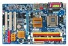
GA-945G-DS3 Motherboard Layout KB_MS ATX_12V LGA775 CPU_FAN COMA LPT VGA USB USB LAN ATX GA-945G-DS3 DDRII1 DDRII2 DDRII3 DDRII4 F_AUDIO AUDIO NB_FAN Intel® 945G RTL8111B PCIE_16 PCIE_3 PCIE_1 CODEC PCIE_2 PCI1 IT8718 PCI2 PCI3 CI CD_IN SPDIF_IO SYS_FAN PWR_FAN CLR_CMOS - Gigabyte GA-945G-DS3 | Manual - Page 8
VGA LGA775 Processor CPU CLK+/-(266/200/133 MHz) PCI Express x16 LAN RJ45 Host Interface DDRII 667/533/400 MHz DIMM(Note) Intel® 945G Dual Channel Memory MIC Line-Out Line-In SPDIF In SPDIF Out 3 PCI 8 USB Ports PCI CLK(33 MHz) (Note) To use a DDRII 667 memory module on the motherboard, - Gigabyte GA-945G-DS3 | Manual - Page 9
read the information in the provided manual. 3. Before using the product, please verify that all cables and power connectors are connected. 4. To prevent damage to the motherboard, please do not allow screws to come in contact with the motherboard circuit or its components. 5. Please make sure - Gigabyte GA-945G-DS3 | Manual - Page 10
fan connector Š 1 Northbridge fan connector Š 1 front panel connector Š 1 front audio connector Š 1 CD In connector Š 1 S/PDIF In/Out connector Š 2 USB 2.0/1.1 connectors for additional 4 ports by cables Š 1 Chassis Intrusion connector Š 1 power LED connector GA-945G-DS3 Motherboard - 10 - - Gigabyte GA-945G-DS3 | Manual - Page 11
Š CPU / System / Power fan speed detection Š CPU warning temperature Š CPU / System / Power fan failure warning Š CPU smart fan control BIOS Š 1 4 Mbit flash ROM Š Use of licensed AWARD BIOS Š PnP 1.0a, DMI 2.0, SM BIOS 2.3, ACPI 1.0b Additional Features Š Supports @BIOS Š Supports Download - Gigabyte GA-945G-DS3 | Manual - Page 12
- CPU: An Intel® Pentium 4 Processor with HT Technology - Chipset: An Intel® Chipset that supports HT Technology - BIOS: A BIOS that supports HT that might cause damage to the CPU during installation.) GA-945G-DS3 Motherboard - 12 - Fig. 4 Once the CPU is properly inserted, please replace the - Gigabyte GA-945G-DS3 | Manual - Page 13
make sure the Male and Female push pin are joined closely. (for detailed installation instructions, please refer to the CPU cooler installation section of the user manual) Fig. 5 Please check the back of motherboard after installing. If the push pin is inserted as the picture, the installation is - Gigabyte GA-945G-DS3 | Manual - Page 14
you are unable to insert the module, please switch the direction. The motherboard supports DDR II memory modules, whereby BIOS will automatically detect memory capacity and specifications. Memory modules are designed so steps when you wish to remove the DIMM module. GA-945G-DS3 Motherboard - 14 - - Gigabyte GA-945G-DS3 | Manual - Page 15
GA-945G-DS3 supports the Dual Channel Technology. After operating the Dual Channel Technology, the bandwidth of memory bus will double. The GA-945G-DS3 is recommended to use memory modules of identical brand, size, chips, and speed), you must install them into DIMM sockets of the same color. The - Gigabyte GA-945G-DS3 | Manual - Page 16
its power source and read the expansion card's installation manual before installing the expansion card in the computer. configure required settings for the expansion card in system BIOS Setup. 8. Install related driver in the operating system. For example: Installing GA-945G-DS3 Motherboard - 16 - - Gigabyte GA-945G-DS3 | Manual - Page 17
. If your OS does not support USB controller, please contact OS vendor for possible patch or driver upgrade. For more information please contact your OS or device(s) vendors. LAN Port The provided Internet connection is Gigabit Ethernet , providing data transfer speeds of 10/100/ 1000Mbps. Center - Gigabyte GA-945G-DS3 | Manual - Page 18
4) SYS_FAN 5) PWR_FAN 6) NB_FAN 7) FDD 8) IDE1 9) SATAII0/1/2/3 10) PWR_LED 11) F_PANEL 12) F_AUDIO 13) CD_IN 14) SPDIF_IO 15) F_USB1 / F_USB2 16) CI 17) CLR_CMOS 18) BATTERY GA-945G-DS3 Motherboard - 18 - - Gigabyte GA-945G-DS3 | Manual - Page 19
connector with its proper location on the motherboard and connect tightly. The ATX_12V power connector mainly supplies power to the CPU. If the ATX_12V power connector is -pin ATX) Pin No. 13 14 15 16 17 18 19 20 21 22 23 24 Definition 3.3V -12V GND PS_ON(soft On/Off) GND GND GND -5V +5V +5V +5V - Gigabyte GA-945G-DS3 | Manual - Page 20
SYS_FAN / PWR_FAN : Pin No. Definition 1 GND 2 +12V 3 Sense 6) NB_FAN (Chip Fan Power Connector) The chip fan will not work if you install it in the wrong direction and sometimes the chip fan will be damaged. Pin No. Definition 1 GND 1 2 +12V 3 NC GA-945G-DS3 Motherboard - 20 - - Gigabyte GA-945G-DS3 | Manual - Page 21
cable while the other end of the cable connects to the FDD drive. The types of FDD drives supported are: 360 KB, 720 KB, 1.2 MB, 1.44 MB and 2.88 MB. Before attaching the FDD cable , please refer to the instructions located on the IDE device). Before attaching the IDE cable, please take note of - Gigabyte GA-945G-DS3 | Manual - Page 22
7 Definition GND TXP TXN GND RXN RXP GND 10) PWR_LED The PWR_LED connector is connected with the system power indicator to indicate whether the system is on/off. It will blink when the system enters suspend mode(S1). Pin No. Definition 1 MPD+ 1 2 MPD- 3 MPD- GA-945G-DS3 Motherboard - 22 - Gigabyte GA-945G-DS3 | Manual - Page 23
English 11) F_PANEL (Front Panel Jumper) Please connect the power LED, PC speaker, reset switch and power switch etc. of your chassis front panel to the F_PANEL connector according to the pin assignment below. Message LED/ Power/ Sleep LED Power Switch Speaker Connector MSG+ MSG- PW+ PWSPEAK+ - Gigabyte GA-945G-DS3 | Manual - Page 24
an AC97 front panel audio module to this connector, please refer to the instructions on page 65 about the software settings. 13) CD_IN (CD In Connector) Connect CD-ROM or DVD-ROM audio out to the connector. Pin No. Definition 1 CD-L 1 2 GND 3 GND 4 CD-R GA-945G-DS3 Motherboard - 24 - - Gigabyte GA-945G-DS3 | Manual - Page 25
connector will make the device unable to work or even damage it. For optional S/PDIF cable, please contact your local dealer. 26 15 Pin No. 1 2 3 4 5 6 Definition Power No Pin SPDIF SPDIFI GND GND 15) F_ USB1 / F_USB2 (Front USB Connector) Be careful with the polarity of the front USB connector - Gigabyte GA-945G-DS3 | Manual - Page 26
system to detect if the chassis cover is removed. You can check the "Case Opened" status in BIOS Setup. Pin No. Definition 1 1 Signal 2 GND 17) CLR_CMOS (Clear CMOS) You may clear the CMOS data to its improper use of this header. Open: Normal Short: Clear CMOS GA-945G-DS3 Motherboard - 26 - - Gigabyte GA-945G-DS3 | Manual - Page 27
is incorrectly replaced. Replace only with the same or equivalent type recommended by the manufacturer. Dispose of used batteries according to the manufacturer's instructions. If you want to erase CMOS... 1. Turn off the computer and unplug the power cord. 2. Gently take out the battery and put it - Gigabyte GA-945G-DS3 | Manual - Page 28
English GA-945G-DS3 Motherboard - 28 - - Gigabyte GA-945G-DS3 | Manual - Page 29
system. @BIOS is a Windows-based utility that does not require users to boot to DOS before upgrading BIOS but directly download and update BIOS from the Internet. CONTROL KEYS Enter> Move to select item Select Item Main Menu - Gigabyte GA-945G-DS3 | Manual - Page 30
in the BIOS Setup when somehow the system is not stable as usual. This action makes the system reset to the default settings for stability. 3. The BIOS Setup menus described in this chapter are for reference only and may differ from the exact settings for your motherboard. GA-945G-DS3 Motherboard - Gigabyte GA-945G-DS3 | Manual - Page 31
setup page includes all the items in standard compatible BIOS. „ Advanced BIOS Features This setup page includes all the items of is the System auto detect Temperature, voltage, fan, speed. „ MB Intelligent Tweaker(M.I.T.) This setup page is control CPU clock and frequency ratio. „ Load Fail-Safe - Gigabyte GA-945G-DS3 | Manual - Page 32
[None] Drive A Floppy 3 Mode Support Halt On Base Memory Extended Memory Value F10: Save F6: Fail-Safe Defaults ESC to Sat, determined by the BIOS and is display-only The month Manual automatic detection step and allow for faster system start up. User can manually GA-945G-DS3 Motherboard - 32 - - Gigabyte GA-945G-DS3 | Manual - Page 33
capacity. Floppy 3 Mode Support (for Japan Area) Disabled motherboard, or 640 K for systems with 640 K or more memory installed on the motherboard. Extended Memory The BIOS determines how much extended memory is present during the POST. This is the amount of memory located above 1 MB in the CPU - Gigabyte GA-945G-DS3 | Manual - Page 34
BIOS Features ` Hard Disk Boot Priority First Boot Device Second Boot Device Third Boot Device Password Check HDD S.M.A.R.T. Capability CPU F5: Previous Values +/-/PU/PD: Value F10: Save F6: Fail-Safe Defaults ESC: Exit F1: General Help supports this function. GA-945G-DS3 Motherboard - 34 - - Gigabyte GA-945G-DS3 | Manual - Page 35
supported. Disabled (Default value) Disable CPU windows XP. (Default value) No-Execute Memory Protect (Note) Enabled Disabled Enable No-Execute Memory Protect function. (Default value) Disable No-Execute Memory Protect function. CPU . If you wish to see BIOS POST screen, set this item to - Gigabyte GA-945G-DS3 | Manual - Page 36
2.0 Controller USB Keyboard Support USB Mouse Support Legacy USB storage detect +/-/PU/PD: Value F10: Save F6: Fail-Safe Defaults ESC: Exit F1 BIOS will auto detect. (Default value) Set On-Chip SATA mode to Combined, you can use up to 4 HDDs on the motherboard GA-945G-DS3 Motherboard - 36 - - Gigabyte GA-945G-DS3 | Manual - Page 37
0.0m 0.0m 0.0m 0.0m Item Help Menu Level` KLJI: Move Enter: Select F5: Previous Values +/-/PU/PD: Value F10: Save F6: Fail-Safe Defaults ESC: Exit F1: General Help F7: Optimized Defaults This motherboard incorporates cable diagnostic feature designed to detect the status of the attached LAN - Gigabyte GA-945G-DS3 | Manual - Page 38
normal speed of 10/100/1000Mbps in Windows mode or when the LAN Boot ROM is activated. When a Cable Problem Occurs... If a cable problem occurs function. (Default value) Onboard Serial Port 1 Auto BIOS will automatically setup the port 1 address. 3F8/IRQ4 1. GA-945G-DS3 Motherboard - 38 - - Gigabyte GA-945G-DS3 | Manual - Page 39
KLJI: Move Enter: Select F5: Previous Values +/-/PU/PD: Value F10: Save F6: Fail-Safe Defaults ESC: Exit F1: General Help F7: Optimized Defaults ACPI Suspend to S1/POS(Power On Suspend). (Default value) S3(STR) Set ACPI suspend type to S3/STR(Suspend To RAM). Soft-Off by PWR-BTTN BIOS Setup - Gigabyte GA-945G-DS3 | Manual - Page 40
system always in "On" state. Memory When AC-power back to the system, the system will return to the Last state before AC-power off. GA-945G-DS3 Motherboard - 40 - - Gigabyte GA-945G-DS3 | Manual - Page 41
10,11,12,14,15 PCI 3 IRQ Assignment Auto 3,4,5,7,9,10,11,12,14,15 +/-/PU/PD: Value F10: Save F6: Fail-Safe Defaults ESC: Exit F1: General Help F7: Optimized Defaults Auto assign IRQ to PCI 1. (Default value) (Default value) Set IRQ 3,4,5,7,9,10,11,12,14,15 to PCI 3. - 41 - BIOS Setup - Gigabyte GA-945G-DS3 | Manual - Page 42
. Monitor CPU temperature at 80oC / 176oF. Monitor CPU temperature at 90oC / 194oF. Disable this function. (Default value) CPU/POWER/SYSTEM FAN Fail Warning Disabled Enabled Disable the fan fail warning function. (Default value) Enable the fan fail warning function. GA-945G-DS3 Motherboard - 42 - Gigabyte GA-945G-DS3 | Manual - Page 43
In fact, the Voltage option can be used for CPU fans with 3-pin or 4-pin power cables. However, some 4-pin CPU fan power cables are not designed following Intel 4-Wire fans PWM control specifications. With such CPU fans, selecting PWM will not effectively reduce the fan speed. - 43 - BIOS Setup - Gigabyte GA-945G-DS3 | Manual - Page 44
C.I.A.2 to Racing. (Automatically increase CPU frequency(9%,11%) by CPU loading. Turbo Set C.I.A.2 to Turbo. (Automatically increase CPU frequency(15%,17%) by CPU loading. (Note) This item will show up when you install a processor which supports this function. GA-945G-DS3 Motherboard - 44 - - Gigabyte GA-945G-DS3 | Manual - Page 45
Control Normal Supply FSB voltage as FSB required. (Default value) +0.1V ~ +0.3V Increase FSB voltage by 0.1V to 0.3V. CPU Voltage Control Supports adjustable CPU vcore. The adjustable range is dependent on CPUs. (Default value: Normal) Please note that by overclocking your system through the - Gigabyte GA-945G-DS3 | Manual - Page 46
Standard CMOS Features Load Fail-Safe Defaults ` Advanced BIOS Features Load Optimized Defaults ` Integrated Peripherals Set Supervisor Password Selecting this field loads the factory defaults for BIOS and Chipset Features which the system automatically detects. GA-945G-DS3 Motherboard - 46 - - Gigabyte GA-945G-DS3 | Manual - Page 47
the system will boot and you can enter Setup freely. The BIOS Setup program allows you to specify two separate passwords: SUPERVISOR PASSWORD and only basic items. If you select "System" at "Password Check" in Advance BIOS Features Menu, you will be prompted for the password every time the system is - Gigabyte GA-945G-DS3 | Manual - Page 48
1984-2007 Award Software ` Standard CMOS Features Load Fail-Safe Defaults ` Advanced BIOS Features Load Optimized Defaults ` Integrated Peripherals Set Supervisor Password ` Power Management without saving to RTC CMOS. Type "N" will return to Setup Utility. GA-945G-DS3 Motherboard - 48 - - Gigabyte GA-945G-DS3 | Manual - Page 49
will continue to install other drivers. System will reboot automatically after install the drivers, afterward you can install others application. For USB2.0 driver support under Windows XP operating system, please use Windows Service Pack. After install Windows Service Pack, it will show a question - Gigabyte GA-945G-DS3 | Manual - Page 50
Software Applications This page displays all the tools that Gigabyte developed and some free software, you can choose anyone you want and press "install" to install them. 3-3 Driver CD Information This page lists the contents of software and drivers in this CD-title. GA-945G-DS3 Motherboard - 50 - - Gigabyte GA-945G-DS3 | Manual - Page 51
English 3-4 Hardware Information This page lists all device you have for this motherboard. 3-5 Contact Us Please see the last page for details. - 51 - Install Drivers - Gigabyte GA-945G-DS3 | Manual - Page 52
English GA-945G-DS3 Motherboard - 52 - - Gigabyte GA-945G-DS3 | Manual - Page 53
convenient Windows based system performance enhancement and manageability utility. Featuring several powerful yet easy to use tools such as 1) Overclocking for enhancing system performance, 2) C.I.A. and M.I.B. for special enhancement for CPU and Memory, 3) Smart-Fan control for managing fan speed - Gigabyte GA-945G-DS3 | Manual - Page 54
data. Supporting Microsoft operating systems including Windows XP/ speed of the hard disk will affect the data backup speed. 3. It is recommended that Xpress Recovery2 be immediately installed once you complete installations of OS and all required drivers as well as software. GA-945G-DS3 Motherboard - Gigabyte GA-945G-DS3 | Manual - Page 55
main Windows 2000, be sure to execute the EnableBigLba.exe program from the driver CD before data backup. 2. It is normal that data backup takes longer time than data restoration. 3. Xpress Recovery2 is compliant with the GPL regulations. 4. On a few motherboards based on Nvidia chipsets, BIOS - Gigabyte GA-945G-DS3 | Manual - Page 56
Utility v2.02 Flash Type/Size MXIC SPI Serial Fla 512K Keep DMI Data Enable Update BIOS from Drive Sa0vefilBeI(Os)SfotounDdrive EnteFr l:oRppuyn A :Move ESC:Reset :Power Off HDD 0-0 Total size : 0 F5 : Refresh GA-945G-DS3 Motherboard Free size : 0 DEL : Delete - 56 - - Gigabyte GA-945G-DS3 | Manual - Page 57
press ENTER. Make sure again the BIOS file matches your motherboard model. Step 2: The process of system reading the BIOS file from the floppy disk is displayed on the screen. When the message "Are you sure to update BIOS?" appears, press ENTER. The BIOS update will begin and the current process - Gigabyte GA-945G-DS3 | Manual - Page 58
" icon b. Click "Update New BIOS" c. Please select "All Files" in dialog box while opening the old file. d. Please search for BIOS unzip file, downloading from internet or any other methods (such as: 945GDS3.F2). e. Complete update process following the instruction. GA-945G-DS3 Motherboard - 58 - - Gigabyte GA-945G-DS3 | Manual - Page 59
. II. In method II, be sure that motherboard's model name in BIOS unzip file are the same as your motherboard's. Otherwise, your system won't boot. III. In method I, if the BIOS file you need cannot be found in @BIOSTM server, please go onto Gigabyte's web site for downloading and updating it - Gigabyte GA-945G-DS3 | Manual - Page 60
shown in the picture to the right. The jack retasking capability supported by HD Audio allows users to change the function for each Following pictures are in Windows XP) Center/Subwoofer Speaker Out Rear Speaker Out Side Speaker Out Line In Line Out (Front Speaker Out GA-945G-DS3 Motherboard - 60 - - Gigabyte GA-945G-DS3 | Manual - Page 61
the stereo output is applied. STEP 1 : After installation of the audio driver, you should find an Audio Manager icon in your system tray (you headphone to the rear Line Out jack, a small window will pop up and ask you what type of equipment is connected. Choose Headphone or Line Out depending on the - Gigabyte GA-945G-DS3 | Manual - Page 62
window will pop up and ask you what type of equipment is connected. Choose a device depending on the type of speaker connected (4-channel audio consists of Front Speaker Out (Line Out) and Rear Speaker Out) and then click OK. The 4channel audio setup is completed. GA-945G-DS3 Motherboard - 62 - Gigabyte GA-945G-DS3 | Manual - Page 63
driver, the audio jacks on the motherboard and the surround cable, a small window will pop up and ask you what type of equipment is connected. Choose a device depending on the type of speaker connected (6-channel audio consists of Front Speaker Out (Line - Gigabyte GA-945G-DS3 | Manual - Page 64
the audio driver, you should to the audio jacks on the motherboard and the surround cable, a small window will pop up and ask you what Line Out), Rear Speaker Out, Center/Subwoofer Speaker Out, and Side Speaker Out) then click OK. The 8-channel audio setup is completed. GA-945G-DS3 Motherboard - Gigabyte GA-945G-DS3 | Manual - Page 65
as desired. AC'97 Audio Configuration: To enable the front panel audio connector to support AC97 Audio mode, go to the Audio Control Panel and click the Audio I/O tab. In the ANALOG area, click the Tool icon and then select the Disable front panel jack detection check box. This action completes - Gigabyte GA-945G-DS3 | Manual - Page 66
: System boots successfully 2 short: CMOS setting error 1 long 1 short: DRAM or M/B error 1 long 2 short: Monitor or display card error 1 long 3 short: Keyboard error 1 long 9 short: BIOS ROM error Continuous long beeps: DRAM error Continuous short beeps: Power error GA-945G-DS3 Motherboard - 66 - - Gigabyte GA-945G-DS3 | Manual - Page 67
- 67 - Appendix English - Gigabyte GA-945G-DS3 | Manual - Page 68
English GA-945G-DS3 Motherboard - 68 - - Gigabyte GA-945G-DS3 | Manual - Page 69
- 69 - Appendix English - Gigabyte GA-945G-DS3 | Manual - Page 70
. 814 Xian TEL: +86-29-85531943 FAX: +86-29-85539821 Shenyang TEL: +86-24-83992901 FAX: +86-24-83992909 y India GIGABYTE TECHNOLOGY (INDIA) LIMITED WEB address : http://www.gigabyte.in y Australia GIGABYTE TECHNOLOGY PTY. LTD. WEB address : http://www.gigabyte.com.au GA-945G-DS3 Motherboard - 70 - - Gigabyte GA-945G-DS3 | Manual - Page 71
BYTE Technology Co., Ltd. in SERBIA & MONTENEGRO WEB address : http://www.gigabyte.co.yu y GIGABYTE Global Service System To submit a technical or non-technical (Sales/ Marketing) question, please link to : http://ggts.gigabyte.com.tw Then select your language to enter the system. - 71 - Appendix - Gigabyte GA-945G-DS3 | Manual - Page 72
- 72 -
-
 1
1 -
 2
2 -
 3
3 -
 4
4 -
 5
5 -
 6
6 -
 7
7 -
8
-
9
-
10
-
11
-
12
-
13
-
14
-
15
-
16
-
17
-
18
-
19
-
20
-
21
-
22
-
23
-
24
-
25
-
26
-
27
-
28
-
29
-
30
-
31
-
32
-
33
-
34
-
35
-
36
-
37
-
38
-
39
-
40
-
41
-
42
-
43
-
44
-
45
-
46
-
47
-
48
-
49
-
50
-
51
-
52
-
53
-
54
-
55
-
56
-
57
-
58
-
59
-
60
-
61
-
62
-
63
-
64
-
65
-
66
-
67
-
68
-
69
-
70
-
71
-
72
 |
 |

GA-945G-DS3
Intel
®
Core
TM
2 Extreme dual-core / Core
TM
2 Duo /
Intel
®
Pentium
®
D / Pentium
®
4 LGA775 Processor Motherboard
User's Manual
Rev. 3301
12ME-945GDS3-3301R
*
The WEEE marking on the product indicates this product must not be disposed of with user's other household waste
and must be handed over to a designated collection point for the recycling of waste electrical and electronic equipment!!
*
The WEEE marking applies only in European Union's member states.