Gigabyte GA-945GME-DS2 Manual
Gigabyte GA-945GME-DS2 Manual
 |
View all Gigabyte GA-945GME-DS2 manuals
Add to My Manuals
Save this manual to your list of manuals |
Gigabyte GA-945GME-DS2 manual content summary:
- Gigabyte GA-945GME-DS2 | Manual - Page 1
GA-945GME-DS2 Intel® CoreTM 2 Extreme dual-core / CoreTM 2 Duo / Intel® Pentium® D / Pentium® 4 / Celeron® D LGA775 Processor Motherboard User's Manual Rev. 3001 12ME-945GMEDR-3001R * The WEEE marking on the product indicates this product must not be disposed of with user's other household waste and - Gigabyte GA-945GME-DS2 | Manual - Page 2
Motherboard GA-945GME-DS2 Jan. 31, 2007 Motherboard GA-945GME-DS2 Jan. 31. 2007 - Gigabyte GA-945GME-DS2 | Manual - Page 3
product information and specifications, please carefully read the "Product User Manual". „ For detailed information related to Gigabyte's unique features, please go to "Technology Guide" section on Gigabyte's website to read or download the information you need. For more product details, please - Gigabyte GA-945GME-DS2 | Manual - Page 4
OptionalAccessories ...6 GA-945GME-DS2 Motherboard Layout 7 Block Diagram ...8 Chapter 1 Hardware Installation 9 1-1 Considerations Prior to Installation 9 1-2 Feature Summary 10 1-3 Installation of the CPU and CPU Cooler 12 1-3-1 Installation of the CPU 12 1-3-2 Installation of the CPU Cooler - Gigabyte GA-945GME-DS2 | Manual - Page 5
53 3-5 Contact Us ...53 Chapter 4 Appendix 55 4-1 Unique Software Utilities 55 4-1-1 EasyTune 5 Introduction 55 4-1-2 Xpress Recovery2 Introduction 56 4-1-3 Flash BIOS Method Introduction 58 4-1-4 2- / 4- / 6- / 8- Channel Audio Function Introduction 62 4-2 Troubleshooting 68 - 5 - - Gigabyte GA-945GME-DS2 | Manual - Page 6
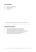
Item Checklist IDE Cable x 1 and FDD Cable x 1 SATA 3Gb/s Cable x 2 I/O Shield * The items listed above are for reference only, and are subject to change without notice. Optional Accessories Š 2 Ports USB 2.0 Cable (Part Number: 12CR1-1UB030-51/R) Š 4 Ports USB 2.0 Cable (Part Number: 12CR1- - Gigabyte GA-945GME-DS2 | Manual - Page 7
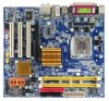
GA-945GME-DS2 Motherboard Layout KB_MS ATX_12V CPU_FAN LGA775 IT8718 VGA COMA LPT GA-945GME-DS2 ATX USB R_USB LAN SYS_FAN AUDIO F_AUDIO PCIE_16 PCI1 RTL8110SC PCI2 PCI3 CODEC CD_IN COMB SPDIF_IO Intel® 945G DDRII1 DDRII2 IDE FDD SATAII0 SATAII2 SATAII1 SATAII3 Intel® ICH7 BIOS - Gigabyte GA-945GME-DS2 | Manual - Page 8
Block Diagram PCIe CLK (100 MHz) VGA PCI Express x16 LGA775 Processor CPU CLK+/-(266/200/133 MHz) Host Interface DDRII 667/533/400 MHz DIMM(Note) Intel® 945G Dual Channel Memory GMCH CLK (266/200/133 MHz) PCI Bus x1 RTL 8110SC RJ45 LAN 3 PCI PCI CLK (33 MHz) Intel® ICH7 ATA-33 - Gigabyte GA-945GME-DS2 | Manual - Page 9
instructions below: 1. Please turn off the computer and unplug its power cord. 2. When handling the motherboard , avoid touching any metal leads or connectors. 3. It is best to wear an electrostatic discharge (ESD) cuff when handling electronic components (CPU motherboard problem manual - Gigabyte GA-945GME-DS2 | Manual - Page 10
1 system fan connector Š 1 front panel connector Š 1 front audio connector Š 1 CD In connector Š 1 S/PDIF In/Out connector Š 2 USB 2.0/1.1 connectors for additional 4 ports by cables Š 1 COMB connector Š 1 Chassis Intrusion connector Š 1 power LED connector GA-945GME-DS2 Motherboard - 10 - - Gigabyte GA-945GME-DS2 | Manual - Page 11
2.0, SM BIOS 2.3, ACPI 1.0b Additional Features Š Supports @BIOS Š Supports Download Center Š Supports Q-Flash Š Supports EasyTune (only supports Hardware Monitor function) (Note 2) Š Supports Xpress Install Š Supports Xpress Recovery2 Š Supports Xpress BIOS Rescue Bundle Software Š Norton - Gigabyte GA-945GME-DS2 | Manual - Page 12
- CPU: An Intel® Pentium 4 Processor with HT Technology - Chipset: An Intel® Chipset that supports HT Technology - BIOS: A BIOS that supports HT that might cause damage to the CPU during installation.) GA-945GME-DS2 Motherboard - 12 - Fig. 4 Once the CPU is properly inserted, please replace the - Gigabyte GA-945GME-DS2 | Manual - Page 13
make sure the Male and Female push pin are joined closely. (for detailed installation instructions, please refer to the CPU cooler installation section of the user manual) Fig. 5 Please check the back of motherboard after installing. If the push pin is inserted as the picture, the installation is - Gigabyte GA-945GME-DS2 | Manual - Page 14
you are unable to insert the module, please switch the direction. The motherboard supports DDRII memory modules, whereby BIOS will automatically detect memory capacity and specifications. Memory modules are designed so steps when you wish to remove the DIMM module. GA-945GME-DS2 Motherboard - 14 - - Gigabyte GA-945GME-DS2 | Manual - Page 15
English Dual Channel Memory Configuration The GA-945GME-DS2 supports the Dual Channel Technology. After operating the Dual Channel Technology, the bandwidth of memory bus will double. The GA-945GME-DS2 includes 2 DIMM sockets. If you want to operate the Dual Channel Technology, please note the - Gigabyte GA-945GME-DS2 | Manual - Page 16
its power source and read the expansion card's installation manual before installing the expansion card in the computer. 2. card in system BIOS Setup. 8. Install related driver in the operating system. For example: Installing a PCI Express x16 VGA card: When GA-945GME-DS2 Motherboard - 16 - - Gigabyte GA-945GME-DS2 | Manual - Page 17
or data processing devices. VGA Port Monitor can be connected to VGA port. USB Port Before you supports USB controller. If your OS does not support USB controller, please contact OS vendor for possible patch or driver upgrade. For more information please contact your OS or device(s) vendors. LAN - Gigabyte GA-945GME-DS2 | Manual - Page 18
to the default speakers settings, the ~ audio jacks can be reconfigured to perform different functions via the audio software. Only microphones still MUST be connected to F_PANEL 11) F_AUDIO 12) CD_IN 13) SPDIF_IO 14) F_USB1 / F_USB2 15) COMB 16) CLR_CMOS 17) CI GA-945GME-DS2 Motherboard - 18 - - Gigabyte GA-945GME-DS2 | Manual - Page 19
all components and devices are properly installed. Align the power connector with its proper location on the motherboard and connect tightly. The ATX_12V power connector mainly supplies power to the CPU. If the ATX_12V power connector is not connected, the system will not start. Caution! Please use - Gigabyte GA-945GME-DS2 | Manual - Page 20
to connect the CPU/system fan cable to the CPU_FAN/SYS_FAN connector to prevent CPU damage or system supported are: 360 KB, 720 KB, 1.2 MB, 1.44 MB and 2.88 MB. Before attaching the FDD cable, please take note of the foolproof groove in the FDD connector. 34 33 2 1 GA-945GME-DS2 Motherboard - Gigabyte GA-945GME-DS2 | Manual - Page 21
as Slave (for information on settings, please refer to the instructions located on the IDE device). Before attaching the IDE cable, up to 300 MB/s transfer rate. Please refer to the BIOS setting for the SATA 3Gb/s and install the proper driver in order to work properly. 1 SATAII2 7 1 SATAII0 - Gigabyte GA-945GME-DS2 | Manual - Page 22
1 MPD+ 2 MPD- 3 MPD- 9) BATTERY GA-945GME-DS2 Motherboard Danger of explosion if battery is incorrectly replaced. Replace only with the same or equivalent type recommended by the manufacturer. Dispose of used batteries according to the manufacturer's instructions. If you want to erase CMOS - Gigabyte GA-945GME-DS2 | Manual - Page 23
English 10) F_PANEL (Front Panel Jumper) Please connect the power LED, PC speaker, reset switch and power switch etc. of your chassis front panel to the F_PANEL connector according to the pin assignment below. Message LED/ Power/ Sleep LED Power Switch Speaker Connector MSG+ MSG- PW+ PWSPEAK+ - Gigabyte GA-945GME-DS2 | Manual - Page 24
an AC97 front panel audio module to this connector, please refer to the instructions on page 67 about the software settings. 12) CD_IN (CD IN Connector) Connect CD-ROM or DVD-ROM audio out to the connector. Pin No. Definition 1 CD-L 1 2 GND 3 GND 4 CD-R GA-945GME-DS2 Motherboard - 24 - - Gigabyte GA-945GME-DS2 | Manual - Page 25
English 13) SPDIF_IO (S/PDIF In/Out Connector) The S/PDIF output is capable of providing digital audio to external speakers or compressed AC3 data to an external Dolby Digital Decoder. Use this feature only when your stereo system has digital input function. - Gigabyte GA-945GME-DS2 | Manual - Page 26
. To clear CMOS, temporarily short the two pins. Default doesn't include the jumper to avoid improper use of this header. Open: Normal Short: Clear CMOS GA-945GME-DS2 Motherboard - 26 - - Gigabyte GA-945GME-DS2 | Manual - Page 27
English 17) CI (Chassis Intrusion, Case Open) This 2-pin connector allows your system to detect if the chassis cover is removed. You can check the "Case Opened" status in BIOS Setup. Pin No. Definition 1 Signal 1 2 GND - 27 - Hardware Installation - Gigabyte GA-945GME-DS2 | Manual - Page 28
English GA-945GME-DS2 Motherboard - 28 - - Gigabyte GA-945GME-DS2 | Manual - Page 29
BIOS, either GIGABYTE's Q-Flash or @BIOS utility can be used. Q-Flash allows the user to quickly and easily update or backup BIOS without entering the operating system. @BIOS is a Windows-based utility that does not require users to boot to DOS before upgrading BIOS but directly download and update - Gigabyte GA-945GME-DS2 | Manual - Page 30
a name. F12 : Load CMOS from BIOS If your system becomes unstable and you load the default BIOS settings, you can use this function to reload the CMOS settings with a CMOS settings profile created before, without the hassles of resetting the CMOS configurations. GA-945GME-DS2 Motherboard - 30 - - Gigabyte GA-945GME-DS2 | Manual - Page 31
setup page includes all the items in standard compatible BIOS. „ Advanced BIOS Features This setup page includes all the items of , voltage, fan, speed. „ Frequency/Voltage Control This setup page is control CPU clock and frequency ratio. „ Load Fail-Safe Defaults Fail-Safe Defaults indicates the - Gigabyte GA-945GME-DS2 | Manual - Page 32
Software 3 Mode Support [1.44M, Manual User can manually BIOS to automatically detect IDE/SATA devices during POST(default) • None Select this if no IDE/SATA devices are used and the system will skip the automatic detection step and allow for faster system start up. GA-945GME-DS2 Motherboard - Gigabyte GA-945GME-DS2 | Manual - Page 33
MB capacity. Floppy 3 Mode Support (for Japan Area) Disabled Normal . All Errors Whenever the BIOS detects a non-fatal error the BIOS. Base Memory The POST of the BIOS will motherboard, or 640 K for systems with 640 K or more memory installed on the motherboard. Extended Memory The BIOS - Gigabyte GA-945GME-DS2 | Manual - Page 34
Software Advanced BIOS Features Hard Disk Boot Priority First Boot Device Second Boot Device Third Boot Device Password Check HDD S.M.A.R.T. Capability CPU by USB-HDD. LAN Select your boot device priority by LAN. Disabled Disable this supports this function. GA-945GME-DS2 Motherboard - 34 - - Gigabyte GA-945GME-DS2 | Manual - Page 35
this feature is only working for operating system with multi processors mode supported. Disabled (Default value) Disable CPU Hyper Threading. Limit CPUID Max. to 3 (Note) Enabled Disabled Note) This item will show up when you install a processor which supports this function. - 35 - BIOS Setup - Gigabyte GA-945GME-DS2 | Manual - Page 36
to Ch. 0 Master/Slave, this function will auto set to Ch. 1 Master/Slave. USB Controller Enabled Enable USB controller. (Default value) Disabled Disable USB controller. GA-945GME-DS2 Motherboard - 36 - - Gigabyte GA-945GME-DS2 | Manual - Page 37
value) Disabled Disable Azalia audio function. Onboard H/W LAN Enabled Disabled Enable onboard H/W LAN function. (Default value) Disable this function. SMART LAN (LAN Cable Diagnostic Function) CMOS Setup Utility-Copyright (C) 1984-2006 Award Software SMART LAN Start detecting at Port - Gigabyte GA-945GME-DS2 | Manual - Page 38
in Windows mode or when the LAN Boot ROM is activated. When a Cable Problem Occurs... If a cable problem occurs on a specified pair of Disable onboard Serial port 1. Onboard Serial Port 2 Auto BIOS will automatically setup the port 2 address. 3F8/IRQ4 Enable GA-945GME-DS2 Motherboard - 38 - - Gigabyte GA-945GME-DS2 | Manual - Page 39
when "Parallel Port Mode" set to "ECP" or "ECP+EPP". 3 Set ECP Mode Use DMA to 3. (Default value) 1 Set ECP Mode Use DMA to 1. - 39 - BIOS Setup - Gigabyte GA-945GME-DS2 | Manual - Page 40
English 2-4 Power Management Setup CMOS Setup Utility-Copyright (C) 1984-2006 Award Software Power Management Setup ACPI Suspend Type Soft-Off by PWR-BTTN PME Event Wake (Default value) Double Click Double click on PS/2 mouse left button to power on the system. GA-945GME-DS2 Motherboard - 40 - - Gigabyte GA-945GME-DS2 | Manual - Page 41
always in "On" state. Memory When AC-power back to the system, the system will return to the Last state before AC-power off. - 41 - BIOS Setup - Gigabyte GA-945GME-DS2 | Manual - Page 42
English 2-5 PnP/PCI Configurations CMOS Setup Utility-Copyright (C) 1984-2006 Award Software PnP/PCI Configurations PCI 1 IRQ Assignment PCI 2 IRQ Assignment PCI 3 IRQ Assignment [Auto] [Auto] to PCI 3. (Default value) Set IRQ 3,4,5,7,9,10,11,12,14,15 to PCI 3. GA-945GME-DS2 Motherboard - 42 - - Gigabyte GA-945GME-DS2 | Manual - Page 43
(C) 1984-2006 Award Software PC Health Status Reset Case Open Status Case Opened Vcore DDR18V +3.3V +12V Current CPU Temperature Current CPU FAN Speed Current SYSTEM FAN Speed CPU Warning Temperature CPU FAN Fail Warning SYSTEM FAN Fail Warning CPU Smart FAN Control CPU Smart FAN Mode [Disabled - Gigabyte GA-945GME-DS2 | Manual - Page 44
option can be used for CPU fans with 3-pin or 4-pin power cables. However, some 4-pin CPU fan power cables are not designed following Intel 4-Wire fans PWM control specifications. With such CPU fans, selecting PWM will not effectively reduce the fan speed. GA-945GME-DS2 Motherboard - 44 - - Gigabyte GA-945GME-DS2 | Manual - Page 45
set "CPU Host Frequency" to 200 MHz. If you use a 1066 MHz FSB processor, set "CPU Host Frequency" to 266 MHz. Incorrect using it may cause your system broken. For power End-User use only! (Note) This item will show up when you install a processor which supports this function. - 45 - BIOS Setup - Gigabyte GA-945GME-DS2 | Manual - Page 46
SPD data). Wrong frequency settings may cause system unable to boot. Clear CMOS to overcome wrong frequency issue. Memory Frequency (Mhz) The values depend on CPU Host Frequency(Mhz) and System Memory Multiplier setting. GA-945GME-DS2 Motherboard - 46 - - Gigabyte GA-945GME-DS2 | Manual - Page 47
parameters that allow minimum system performance. 2-9 Load Optimized Defaults CMOS Setup Utility-Copyright (C) 1984-2006 Award Software Standard CMOS Features Advanced BIOS Features Integrated Peripherals Power Management Setup PnP/PCI Configurations PC Health Status Frequency/Voltage Control Esc - Gigabyte GA-945GME-DS2 | Manual - Page 48
BIOS Features Menu, you will be prompted for the password every time the system is rebooted or any time you try to enter Setup Menu. If you select "Setup" at "Password Check" in Advance BIOS Features Menu, you will be prompted only when you try to enter Setup. GA-945GME-DS2 Motherboard - 48 - Gigabyte GA-945GME-DS2 | Manual - Page 49
. Type "N" will return to Setup Utility. 2-12 Exit Without Saving CMOS Setup Utility-Copyright (C) 1984-2006 Award Software Standard CMOS Features Advanced BIOS Features Integrated Peripherals Power Management Setup PnP/PCI Configurations PC Health Status Frequency/Voltage Control Esc: Quit F8 - Gigabyte GA-945GME-DS2 | Manual - Page 50
English GA-945GME-DS2 Motherboard - 50 - - Gigabyte GA-945GME-DS2 | Manual - Page 51
Pictures below are shown in Windows XP. Insert the driver CD-title that came with your motherboard into your CD-ROM drive, the driver CD-title will auto start and show the installation guide. If not, please double click the CD-ROM device icon in "My computer", and execute the Run.exe. 3-1 Install - Gigabyte GA-945GME-DS2 | Manual - Page 52
3-2 Software Applications This page displays all the tools that Gigabyte developed and some free software, you can choose anyone you want and press "install" to install them. 3-3 Driver CD Information This page lists the contents of software and drivers in this CD-title. GA-945GME-DS2 Motherboard - Gigabyte GA-945GME-DS2 | Manual - Page 53
English 3-4 Hardware Information This page lists all device you have for this motherboard. 3-5 Contact Us Please see the last page for details. - 53 - Install Drivers - Gigabyte GA-945GME-DS2 | Manual - Page 54
English GA-945GME-DS2 Motherboard - 54 - - Gigabyte GA-945GME-DS2 | Manual - Page 55
LEDs Shows the current functions status 9. GIGABYTE Logo Log on to GIGABYTE website 10. Help button Display EasyTuneTM 5 Help file 11. Exit or Minimize button Quit or Minimize EasyTuneTM 5 software (Note) EasyTune 5 functions may vary depending on different motherboards. - 55 - Appendix - Gigabyte GA-945GME-DS2 | Manual - Page 56
least 64M bytes of system memory 3. VESA-supported VGA cards How to use the Xpress Recovery2 Initial BIOS v6.00PG, An Energy Star Ally Copyright (C) 1984-2006, Award Software, Inc. Intel I945 BIOS for 945GME-DS2 DA . . . . : BIOS drivers as well as software. GA-945GME-DS2 Motherboard - 56 - - Gigabyte GA-945GME-DS2 | Manual - Page 57
Exit the main screen and not supported. 6. Does not support RAID/ driver CD before data backup. 2. It is normal that data backup takes longer time than data restoration. 3. Xpress Recovery2 is compliant with the GPL regulations. 4. On a few motherboards based on Nvidia chipsets, BIOS update - Gigabyte GA-945GME-DS2 | Manual - Page 58
using Q-Flash to update BIOS: 1. From GIGABYTE's website, download the latest compressed BIOS update file that matches your motherboard model 2. Extract the downloaded BIOS files and save the new BIOS file (e.g. 9GMEDS23.FA) to your floppy disk or hard disk. Note: Q-Flash only supports hard disks or - Gigabyte GA-945GME-DS2 | Manual - Page 59
press ENTER. Make sure again the BIOS file matches your motherboard model. Step 2: The process of system reading the BIOS file from the floppy disk is displayed on the screen. When the message "Are you sure to update BIOS?" appears, press ENTER. The BIOS update will begin and the current process - Gigabyte GA-945GME-DS2 | Manual - Page 60
Update" icon b. Click "Update New BIOS" c. Please select "All Files" in dialog box while opening the old file. d. Please search for BIOS unzip file, downloading from internet or any other methods (such as: 9GMEDS23.FA). e. Complete update process following the instruction. GA-945GME-DS2 Motherboard - Gigabyte GA-945GME-DS2 | Manual - Page 61
II, be sure that motherboard's model name in BIOS unzip file are the same as your motherboard's. Otherwise, your system won't boot. III. In method I, if the BIOS file you need cannot be found in @BIOSTM server, please go onto Gigabyte's web site for downloading and updating it according to method - Gigabyte GA-945GME-DS2 | Manual - Page 62
supported by HD Audio allows users to change the function for each audio jack by the audio software audio driver, you should find an Audio Manager icon in your system tray (you can also find the icon in Control Panel). Doubleclick the icon to open the Audio Control Panel. GA-945GME-DS2 Motherboard - Gigabyte GA-945GME-DS2 | Manual - Page 63
. Choose Headphone or Line Out depending on the device connected and click OK. The 2-channel audio setup is completed. Setting Up 4-Channel Audio STEP 1 : After installation of the audio driver, you should find an Audio Manager icon in your system tray (you can also find the icon in Control Panel - Gigabyte GA-945GME-DS2 | Manual - Page 64
The 4channel audio setup is completed. Setting Up 6-Channel Audio STEP 1 : After installation of the audio driver, you should find an Audio Manager icon in your system tray (you can also find the icon in Control Panel). Doubleclick the icon to open the Audio Control Panel. GA-945GME-DS2 Motherboard - Gigabyte GA-945GME-DS2 | Manual - Page 65
6CH Speaker. STEP 3: Connect the 6-channel speakers to the audio jacks on the motherboard and the surround cable, a small window will pop up . The 6-channel audio setup is completed. Setting Up 8-Channel Audio STEP 1 : After installation of the audio driver, you should find an Audio Manager icon in - Gigabyte GA-945GME-DS2 | Manual - Page 66
of Front Speaker Out (Line Out), Rear Speaker Out, Center/Subwoofer Speaker Out, and Side Speaker Out) then click OK. The 8-channel audio setup is completed. Sound Effect Configuration: At the Sound Effect menu, users can adjust sound option settings as desired. GA-945GME-DS2 Motherboard - 66 - - Gigabyte GA-945GME-DS2 | Manual - Page 67
English AC'97 Audio Configuration: To enable the front panel audio connector to support AC97 Audio mode, go to the Audio Control Panel and click the Audio I/O tab. In the ANALOG area, click the Tool icon and then select the Disable front panel jack detection check box. This action completes the AC' - Gigabyte GA-945GME-DS2 | Manual - Page 68
System boots successfully 2 short: CMOS setting error 1 long 1 short: DRAM or M/B error 1 long 2 short: Monitor or display card error 1 long 3 short: Keyboard error 1 long 9 short: BIOS ROM error Continuous long beeps: DRAM error Continuous short beeps: Power error GA-945GME-DS2 Motherboard - 68 - - Gigabyte GA-945GME-DS2 | Manual - Page 69
- 69 - Appendix English - Gigabyte GA-945GME-DS2 | Manual - Page 70
814 Xian TEL: +86-29-85531943 FAX: +86-29-85539821 Shenyang TEL: +86-24-83992901 FAX: +86-24-83992909 y India GIGABYTE TECHNOLOGY (INDIA) LIMITED WEB address : http://www.gigabyte.in y Australia GIGABYTE TECHNOLOGY PTY. LTD. WEB address : http://www.gigabyte.com.au GA-945GME-DS2 Motherboard - 70 - - Gigabyte GA-945GME-DS2 | Manual - Page 71
BYTE Technology Co., Ltd. in SERBIA & MONTENEGRO WEB address : http://www.gigabyte.co.yu y GIGABYTE Global Service System To submit a technical or non-technical (Sales/ Marketing) question, please link to : http://ggts.gigabyte.com.tw Then select your language to enter the system. - 71 - Appendix - Gigabyte GA-945GME-DS2 | Manual - Page 72
- 72 -
-
 1
1 -
 2
2 -
 3
3 -
 4
4 -
 5
5 -
 6
6 -
 7
7 -
8
-
9
-
10
-
11
-
12
-
13
-
14
-
15
-
16
-
17
-
18
-
19
-
20
-
21
-
22
-
23
-
24
-
25
-
26
-
27
-
28
-
29
-
30
-
31
-
32
-
33
-
34
-
35
-
36
-
37
-
38
-
39
-
40
-
41
-
42
-
43
-
44
-
45
-
46
-
47
-
48
-
49
-
50
-
51
-
52
-
53
-
54
-
55
-
56
-
57
-
58
-
59
-
60
-
61
-
62
-
63
-
64
-
65
-
66
-
67
-
68
-
69
-
70
-
71
-
72
 |
 |

GA-945GME-DS2
Intel
®
Core
TM
2 Extreme dual-core / Core
TM
2 Duo /
Intel
®
Pentium
®
D / Pentium
®
4 / Celeron
®
D
LGA775 Processor Motherboard
User's Manual
Rev. 3001
12ME-945GMEDR-3001R
*
The WEEE marking on the product indicates this product must not be disposed of with user's other household waste
and must be handed over to a designated collection point for the recycling of waste electrical and electronic equipment!!
*
The WEEE marking applies only in European Union's member states.