Gigabyte GA-945GZM-S2 Manual
Gigabyte GA-945GZM-S2 Manual
 |
UPC - 818313003256
View all Gigabyte GA-945GZM-S2 manuals
Add to My Manuals
Save this manual to your list of manuals |
Gigabyte GA-945GZM-S2 manual content summary:
- Gigabyte GA-945GZM-S2 | Manual - Page 1
GA-945GZM-S2 Intel® CoreTM 2 Extreme dual-core / CoreTM 2 Duo / Intel® Pentium® D / Pentium® 4 / Celeron® D LGA775 Processor Motherboard User's Manual Rev. 6601 12ME-945GZMS2-6601R * The WEEE marking on the product indicates this product must not be disposed of with user's other household waste and - Gigabyte GA-945GZM-S2 | Manual - Page 2
Motherboard GA-945GZM-S2 Jan. 12, 2007 Motherboard GA-945GZM-S2 Jan. 12, 2007 - Gigabyte GA-945GZM-S2 | Manual - Page 3
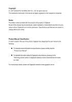
: „ For detailed product information and specifications, please carefully read the "Product User Manual". „ For detailed information related to Gigabyte's unique features, please go to the "Technology Guide" section on Gigabyte's website to read or download the information you need. For more product - Gigabyte GA-945GZM-S2 | Manual - Page 4
Table of Contents ItemChecklist ...6 OptionalAccessories ...6 GA-945GZM-S2 Motherboard Layout 7 Block Diagram ...8 Chapter 1 Hardware CMOS Features 32 2-2 Advanced BIOS Features 34 2-3 IntegratedPeripherals 36 2-4 Power Management Setup 40 2-5 PnP/PCI Configurations 42 2-6 PC Health Status 43 - Gigabyte GA-945GZM-S2 | Manual - Page 5
...53 Chapter 4 Appendix 55 4-1 Unique Software Utilities 55 4-1-1 EasyTune 5 Introduction 55 4-1-2 Xpress Recovery2 Introduction 56 4-1-3 Flash BIOS Method Introduction 58 4-1-4 2- / 4- / 6- / 8- Channel Audio Function Introduction 62 4-2 Troubleshooting 67 - 5 - - Gigabyte GA-945GZM-S2 | Manual - Page 6
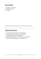
Item Checklist IDE Cable x 1, FDD Cable x 1 SATA 3Gb/s Cable x 2 I/O Shield * The items listed above are for reference only, and are subject to change without notice. Optional Accessories Š 2 Ports USB 2.0 Cable (Part Number: 12CR1-1UB030-51/R) Š 4 Ports USB 2.0 Cable (Part Number: 12CR1-1UB030-21 - Gigabyte GA-945GZM-S2 | Manual - Page 7
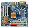
GA-945GZM-S2 Motherboard Layout KB_MS ATX_12V LGA775 CPU_FAN GA-945GZM-S2 ATX IT8718 COMA VGA LPT R_USB USB_LAN SYS _FAN AUDIO F_AUDIO RTL8110SC Intel® 945 PCIE_16 PCI1 DDRII1 DDRII2 IDE FDD SATAII2 SATAII3 CODEC CD_IN SPDIF_IO - Gigabyte GA-945GZM-S2 | Manual - Page 8
Block Diagram VGA PCIe CLK (100 MHz) LGA775 Processor CPU CLK+/-(266/200/133 MHz) Host Interface DDRII 667/533/400 MHz DIMM Intel® Dual Channel Memory 945 GMCH CLK (266/200/133 MHz) 3 PCI PCI Express x4 PCI Bus RTL 8110SC RJ45 LAN Intel® ICH7 CODEC PCI CLK(33 MHz) BIOS 4 SATA 3Gb/s - Gigabyte GA-945GZM-S2 | Manual - Page 9
instructions below: 1. Please turn off the computer and unplug its power power supply is switched off before unplugging the power manual. 3. Before using the product, please verify that all cables and power on the computer power during the installation have a problem related to the the user manual. 3. - Gigabyte GA-945GZM-S2 | Manual - Page 10
4 / Celeron® D Š L2 cache varies with CPU Front Side Bus Š Supports 1066/800/533 MHz FSB Chipset Northbridge: Intel® 945 Express Chipset Š Southbridge: 4 USB 2.0/1.1 ports by cables Š 1 COMB connector Š 1 power LED connector Š 1 Chassis Intrusion connector GA-945GZM-S2 Motherboard - 10 - - Gigabyte GA-945GZM-S2 | Manual - Page 11
Internet Security (OEM version) Form Factor Š Micro ATX form factor; 24.4cm x 22.0cm (Note 1) The GA-945GZM-S2 supports up to PCI Express x4 mode. (please refer to the VGA cards support list on page 16) (Note 2) EasyTune functions may vary depending on different motherboards. - 11 - Hardware - Gigabyte GA-945GZM-S2 | Manual - Page 12
following conditions: 1. Please make sure that the motherboard supports the CPU. 2. Please take note of the one indented graphics card, memory, hard drive, etc. HT functionality requirement that might cause damage to the CPU during installation.) GA-945GZM-S2 Motherboard - 12 - Fig. 4 Once the - Gigabyte GA-945GZM-S2 | Manual - Page 13
detailed installation instructions, please refer to the CPU cooler installation section of the user manual) Fig. 5 Please check the back of motherboard after installing. If the push pin is inserted as the picture, the installation is complete. Fig. 6 Finally, please attach the power - Gigabyte GA-945GZM-S2 | Manual - Page 14
or removing memory modules, please make sure that the computer power is switched off to prevent hardware damage. 3. Memory modules the module, please switch the direction. The motherboard supports DDRII memory modules, whereby BIOS will automatically detect memory GA-945GZM-S2 Motherboard - 14 - - Gigabyte GA-945GZM-S2 | Manual - Page 15
Configuration The GA-945GZM-S2 supports the Dual below: 1. Read the related expansion card's instruction document before install the expansion card into the the expansion card. 6. Replace your computer's chassis cover. 7. Power on the computer, if necessary, setup BIOS utility of expansion card - Gigabyte GA-945GZM-S2 | Manual - Page 16
GV-RX80256D GV-RX30HM128D GV-RX55128D GV-RX85T256V-B GV-RC850T256D-B GV-RX13P256D-RH GV-RX16P256D-RH GV-RX18L256V-B GV-RX18T512V-B AX800XT AX700PRO RX600 XT-TD128 GA-945GZM-S2 Motherboard - 16 - - Gigabyte GA-945GZM-S2 | Manual - Page 17
device(s) such as USB keyboard, mouse, scanner, zip, speaker...etc. have a standard USB interface. Also make sure your OS supports USB controller. If your OS does not support USB controller, please contact OS vendor for possible patch or driver upgrade. For more information please contact your OS or - Gigabyte GA-945GZM-S2 | Manual - Page 18
1 3 4 10 11 12 14 1) ATX_12V 2) ATX (Power Connector) 3) CPU_FAN 4) SYS_FAN 5) IDE 6) FDD 7) SATAII 0 / 1 / 2 / 3 8) PWR_LED 9) F_PANEL 2 5 6 7 17 15 9 13 8 16 10) F_AUDIO 11) CD_IN 12) SPDIF_IO 13) F_USB1 / F_USB2 14) COMB 15) CI 16) CLR_CMOS 17) BATTERY GA-945GZM-S2 Motherboard - 18 - - Gigabyte GA-945GZM-S2 | Manual - Page 19
ATX_12V Pin No. 1 2 3 4 Definition GND GND +12V +12V 12 24 1 13 ATX Pin No. 1 2 3 4 5 6 7 8 9 10 11 12 Definition 3.3V 3.3V GND +5V GND +5V GND Power Good 5V SB(stand by +5V) +12V +12V(Only for 24-pin ATX) 3.3V(Only for 24-pin ATX) Pin No. 13 14 15 16 - Gigabyte GA-945GZM-S2 | Manual - Page 20
power connector wires. A red power connector wire indicates a positive connection and requires a +12V power (hard drive or optical drive). If instructions located on the IDE device). Before attaching the IDE cable, please take note of the foolproof groove in the IDE connector. 40 39 GA-945GZM-S2 - Gigabyte GA-945GZM-S2 | Manual - Page 21
(FDD Connector) The FDD connector is used to connect the FDD cable while the other end of the cable connects to the FDD drive. The types of FDD drives supported are: 360 KB, 720 KB, 1.2 MB, 1.44 MB and 2.88 MB. Before attaching the FDD cable, please take note of the foolproof groove - Gigabyte GA-945GZM-S2 | Manual - Page 22
MSG- PW+ PWSPEAK+ SPEAK- 2 20 1 19 HD+ HD- RESRES+ NC HD (IDE Hard Disk Active LED) SPEAK (Speaker Connector) RES (Reset Switch) PW (Power Switch) MSG (Message LED/Power/Sleep LED) NC GA-945GZM-S2 Motherboard Reset Switch IDE Hard Disk Active LED Pin 1: LED anode(+) Pin 2: LED cathode(-) Pin - Gigabyte GA-945GZM-S2 | Manual - Page 23
No. Definition 1 MIC 2 GND 3 MIC Power 4 NC 5 Line Out (R) 6 NC 7 NC 8 No Pin 9 Line Out (L) 10 NC By default, the audio driver is configured to support HD Audio. To connect an AC97 front panel audio module to this connector, please refer to the instructions on Page 66 about the - Gigabyte GA-945GZM-S2 | Manual - Page 24
will make the device unable to work or even damage it. For optional S/PDIF cable, please contact your local dealer. 51 62 Pin No. 1 2 3 4 5 6 Definition Power No Pin SPDIF SPDIFI GND GND GA-945GZM-S2 Motherboard - 24 - - Gigabyte GA-945GZM-S2 | Manual - Page 25
the device unable to work or even damage it. For optional front USB cable, please contact your local dealer. 9 1 10 2 Pin No. 1 2 3 4 5 6 7 8 9 10 Definition Power (5V) Power (5V) USB DXUSB DyUSB DX+ USB Dy+ GND GND No Pin NC 14) COMB (COMB Connector) Be careful with the polarity of the COMB - Gigabyte GA-945GZM-S2 | Manual - Page 26
. To clear CMOS, temporarily short the two pins. Default doesn't include the jumper to avoid improper use of this header. Open: Normal Short: Clear CMOS GA-945GZM-S2 Motherboard - 26 - - Gigabyte GA-945GZM-S2 | Manual - Page 27
with the same or equivalent type recommended by the manufacturer. Dispose of used batteries according to the manufacturer's instructions. If you want to erase CMOS... 1. Turn off the computer and unplug the power cord. 2. Gently take out the battery and put it aside for about one minute. (Or you can - Gigabyte GA-945GZM-S2 | Manual - Page 28
English GA-945GZM-S2 Motherboard - 28 - - Gigabyte GA-945GZM-S2 | Manual - Page 29
turned on, press the button during the BIOS POST (Power-On Self Test) will take you to the CMOS SETUP screen. You can enter the BIOS setup screen by pressing "Ctrl + F1". If you wish to upgrade to a new BIOS, either GIGABYTE's Q-Flash or @BIOS utility can be used. Q-Flash allows - Gigabyte GA-945GZM-S2 | Manual - Page 30
1984-2007 Award Software ` Standard CMOS Features ` Advanced BIOS Features ` Integrated Peripherals ` Power Management Setup ` PnP/PCI Configurations ` PC Health Status ` Frequency/Voltage Control ESC: and may differ from the exact settings for your motherboard. GA-945GZM-S2 Motherboard - 30 - - Gigabyte GA-945GZM-S2 | Manual - Page 31
This setup page includes all the items of Award special enhanced features. „ Integrated Peripherals This setup page includes all onboard peripherals. „ Power Management Setup This setup page includes all the items of Green function features. „ PnP/PCI Configuration This setup page includes all the - Gigabyte GA-945GZM-S2 | Manual - Page 32
IDE Drive. You can use one of the two methods: • Auto Allows BIOS to automatically detect IDE/SATA devices during POST(default) • None Select this if no IDE/SATA devices are used and the system will skip the automatic detection step and allow for faster system start up. GA-945GZM-S2 Motherboard - Gigabyte GA-945GZM-S2 | Manual - Page 33
; 2.88 M byte capacity. Floppy 3 Mode Support (for Japan Area) Disabled Normal Floppy Drive. (Default value) Drive A Drive A is 3 mode Floppy Drive. Halt on The category determines whether the computer will stop if an error is detected during power up. No Errors The system boot will not - Gigabyte GA-945GZM-S2 | Manual - Page 34
be denied if the correct password is not entered at the prompt. (Default value) (Note) This item will show up when you install a processor which supports this function. GA-945GZM-S2 Motherboard - 34 - - Gigabyte GA-945GZM-S2 | Manual - Page 35
) Enabled Enable CPU Hyper Threading Feature. Please note that this feature is only working for operating system with multi processors mode supported. Disabled (Default value) Disable CPU Hyper Threading. Limit CPUID Max. to 3 (Note) Enabled Disabled Limit CPUID Maximum value to 3 when use - Gigabyte GA-945GZM-S2 | Manual - Page 36
for PATA. Non-Combined Set On-Chip SATA mode to Non-Combined, SATA will be simulated to PATA mode. Support a maximum of 4 SATA devices. PATA devices will be ignored. PATA IDE Set to Ch.0 Master/Slave Set /Slave,this function will auto set to Ch. 1 Master/Slave. GA-945GZM-S2 Motherboard - 36 - - Gigabyte GA-945GZM-S2 | Manual - Page 37
Default value) USB Mouse Support Enabled Enable USB mouse support. Disabled Disable USB mouse support. (Default value) Legacy USB storage detect This option allows users to decide whether to detect USB storage devices, including USB flash drives and USB hard drives during POST. Enabled BIOS - Gigabyte GA-945GZM-S2 | Manual - Page 38
show 0.0m, as shown in the figure above. When LAN Cable Is Functioning Normally... If no cable problem is detected on the LAN cable connected to a Gigabit hub or a 10/100 Mbps hub, the following length shown is the approximate length of the attached LAN cable. GA-945GZM-S2 Motherboard - 38 - - Gigabyte GA-945GZM-S2 | Manual - Page 39
English Onboard LAN Boot ROM This function decide whether to invoke the boot ROM of the onboard LAN chip. Enabled Disabled Enable this function. Disable this function. (Default value) Onboard Serial Port 1 Auto 3F8/IRQ4 BIOS will automatically setup the port 1 address. Enable onboard Serial - Gigabyte GA-945GZM-S2 | Manual - Page 40
POS) Set ACPI suspend type to S1/POS(Power On Suspend). (Default value) S3(STR) Set Press power button then Power off instantly. (Default value) Delay 4 Sec. Press power button 4 sec. to Power off value) Power On by Ring Disabled Enabled Disable Power on by Ring function. Enable Power on by - Gigabyte GA-945GZM-S2 | Manual - Page 41
(Default value) Password Enter from 1 to 5 characters to set the keyboard power on password. Keyboard 98 If your keyboard have "POWER Key" button, you can press the key to power on the system. KB Power ON Password When "Power On by Keyboard" set at Password, you can set the password here. Enter - Gigabyte GA-945GZM-S2 | Manual - Page 42
) Set IRQ 3,4,5,7,9,10,11,12,14,15 to PCI 2. Auto assign IRQ to PCI 3. (Default value) Set IRQ 3,4,5,7,9,10,11,12,14,15 to PCI 3. GA-945GZM-S2 Motherboard - 42 - - Gigabyte GA-945GZM-S2 | Manual - Page 43
English 2-6 PC Health Status CMOS Setup Utility-Copyright (C) 1984-2007 Award Software PC Health Status Reset Case Open Status Case Opened Vcore DDR18V +3.3V +12V Current CPU Temperature Current CPU FAN Speed Current SYSTEM FAN Speed CPU Warning Temperature CPU FAN Fail Warning SYSTEM FAN Fail - Gigabyte GA-945GZM-S2 | Manual - Page 44
option can be used for CPU fans with 3-pin or 4-pin power cables. However, some 4-pin CPU fan power cables are not designed following Intel 4-Wire fans PWM control specifications. With such CPU fans, selecting PWM will not effectively reduce the fan speed. GA-945GZM-S2 Motherboard - 44 - - Gigabyte GA-945GZM-S2 | Manual - Page 45
life expectancy to these components. Please be aware that the menu items are for power users only. CPU Clock Ratio (Note) This setup option will automatically assign by may cause your system broken. For power End-User use only! (Note) This item will show up when you install a processor which - Gigabyte GA-945GZM-S2 | Manual - Page 46
to boot. Clear CMOS to overcome wrong frequency issue. Memory Frequency (Mhz) The values depend on CPU Host Frequency (Mhz) and System Memory Multiplier setting. GA-945GZM-S2 Motherboard - 46 - - Gigabyte GA-945GZM-S2 | Manual - Page 47
Fail-Safe Defaults CMOS Setup Utility-Copyright (C) 1984-2007 Award Software ` Standard CMOS Features ` Advanced BIOS Features ` Integrated Peripherals ` Power Management Setup ` PnP/PCI Configurations ` PC Health Status ` Frequency/Voltage Control ESC: Quit F8: Q-Flash Load Fail-Safe Defaults - Gigabyte GA-945GZM-S2 | Manual - Page 48
Award Software ` Standard CMOS Features ` Advanced BIOS Features ` Integrated Peripherals ` Power Management Setup ` PnP/PCI ConfiguratioEnsnter Password: ` PC Health Status ` Frequency/Voltage Features Menu, you will be prompted only when you try to enter Setup. GA-945GZM-S2 Motherboard - 48 - - Gigabyte GA-945GZM-S2 | Manual - Page 49
11 Save & Exit Setup CMOS Setup Utility-Copyright (C) 1984-2007 Award Software ` Standard CMOS Features ` Advanced BIOS Features ` Integrated Peripherals ` Power Management Setup ` PnP/PCI Configurations ` PC Health Status ` Frequency/Voltage Control ESC: Quit F8: Q-Flash Load Fail-Safe Defaults - Gigabyte GA-945GZM-S2 | Manual - Page 50
English GA-945GZM-S2 Motherboard - 50 - - Gigabyte GA-945GZM-S2 | Manual - Page 51
that came with your motherboard into your CD-ROM drive, the driver CD-title will auto start and show the installation guide. If not, please double click the CD-ROM For USB2.0 driver support under Windows XP operating system, please use Windows Service Pack. After install Windows Service Pack, it will - Gigabyte GA-945GZM-S2 | Manual - Page 52
Applications This page displays all the tools that Gigabyte developed and some free software, you can choose anyone you want and press "install" to install them. 3-3 Driver CD Information This page lists the contents of software and drivers in this CD-title. GA-945GZM-S2 Motherboard - 52 - - Gigabyte GA-945GZM-S2 | Manual - Page 53
English 3-4 Hardware Information This page lists all device you have for this motherboard. 3-5 Contact Us Please see the last page for details. - 53 - Install Drivers - Gigabyte GA-945GZM-S2 | Manual - Page 54
English GA-945GZM-S2 Motherboard - 54 - - Gigabyte GA-945GZM-S2 | Manual - Page 55
support these Unique Software Utilities, please check your MB features.) 4-1-1 EasyTune 5 Introduction EasyTune 5 presents the most convenient Windows based system performance enhancement and manageability utility. Featuring several powerful status 9. GIGABYTE Logo Log on to GIGABYTE website 10. - Gigabyte GA-945GZM-S2 | Manual - Page 56
64M bytes of system memory 3. VESA-supported VGA cards How to use the Xpress Recovery2 the provided driver CD into your CD-ROM drive. Upon system restart, the message which says by simply pressing the key during system power-on. . . Boot from CD/DVD: Press GA-945GZM-S2 Motherboard - 56 - - Gigabyte GA-945GZM-S2 | Manual - Page 57
up hard disks installed with Windows operating systems including DOS and Windows XP/2000/NT/9x/Me. 5. USB hard disks are currently not supported. 6. Does not support RAID/AHCI (class code 0104/0106) hard disks. 7. Capable of backing up and restoring only the first physical hard disk. Hard disks - Gigabyte GA-945GZM-S2 | Manual - Page 58
BIOS: 1. From GIGABYTE's website, download the hard disk. Note: Q-Flash only supports hard disks or flash drives using FAT32/16/12 file system. Drive Sa0vefilBeI(Os)SfotounDdrive EnteFr l:oRppuyn A :Move ESC:Reset :Power Off HDD 0-0 Total size : 0 F5 : Refresh GA-945GZM-S2 - Gigabyte GA-945GZM-S2 | Manual - Page 59
Type/Size MXIC SPI Serial F1a 512K Enter : Run Keep DMI Data Enable !! CopUypBdaItOeSBcIoOmSpflreotemd D- Priavses !! Save BIOS to Drive Please:Mproevses any kEeySCto:Rceosnettinue F10:Power Off Step 4: Press ESC and then ENTER to exit Q-Flash and the system will restart. As the system reboots - Gigabyte GA-945GZM-S2 | Manual - Page 60
Install Fig 3. The @BIOS Utility Click "3" Click "Update New BIOS" Click Start/ Programs/ GIGABYTE/@BIOS Fig 4. Select the desired @BIOS server 1. Methods and steps: I. Update BIOS through as: 9gzms21.F1). e. Complete update process following the instruction. GA-945GZM-S2 Motherboard - 60 - - Gigabyte GA-945GZM-S2 | Manual - Page 61
box. It means to save the current BIOS version. IV. Check out supported motherboard and Flash ROM: In the very beginning, there is "About this program BIOS file you need cannot be found in @BIOSTM server, please go onto Gigabyte's web site for downloading and updating it according to method II. IV. - Gigabyte GA-945GZM-S2 | Manual - Page 62
work correctly. HD Audio With multiple built-in high quality digital-to-analog converters (DACs) that support audio output at up to 192 kHz/24-bit quality and multi-streaming applications, HD Audio is able ). Doubleclick the icon to open the Audio Control Panel. GA-945GZM-S2 Motherboard - 62 - - Gigabyte GA-945GZM-S2 | Manual - Page 63
STEP 2: In the Audio Control Panel, click the Audio I/O tab. In the upper left list, click 2CH Speaker. STEP 3: After a speaker or headphone is plugged into the rear Line Out jack, a small window will pop up and ask you what type of equipment is connected. Choose Headphone or Line Out depending on - Gigabyte GA-945GZM-S2 | Manual - Page 64
audio consists of Front Speaker Out (Line Out), Rear Speaker Out, and Center/Subwoofer Speaker Out) then click OK. The 6-channel audio setup is completed. GA-945GZM-S2 Motherboard - 64 - - Gigabyte GA-945GZM-S2 | Manual - Page 65
8 Channel Audio Setup STEP 1 : After installation of the audio driver, you should find an Audio Manager icon in your system tray (you can also find the icon in Control Panel). Doubleclick the icon to open the Audio Control Panel. STEP 2: In the Audio Control Panel, click the Audio I/O tab. In the - Gigabyte GA-945GZM-S2 | Manual - Page 66
: At the Sound Effect menu, users can adjust sound option settings as desired. AC'97 Audio Configuration: To enable the front panel audio connector to support AC97 Audio mode, go to the Audio Control Panel and click the Audio I/O tab. In the ANALOG area, click the Tool icon and then select - Gigabyte GA-945GZM-S2 | Manual - Page 67
Troubleshooting Below is a collection of general asked questions. To check general asked questions based on a specific motherboard model, please log on to http://www.gigabyte amount of electricity is kept on steps in the manual. If your Turn off power. 2. Disconnect the power cord from problems - Gigabyte GA-945GZM-S2 | Manual - Page 68
English GA-945GZM-S2 Motherboard - 68 - - Gigabyte GA-945GZM-S2 | Manual - Page 69
- 69 - Appendix English - Gigabyte GA-945GZM-S2 | Manual - Page 70
814 Xian TEL: +86-29-85531943 FAX: +86-29-85539821 Shenyang TEL: +86-24-83992901 FAX: +86-24-83992909 y India GIGABYTE TECHNOLOGY (INDIA) LIMITED WEB address : http://www.gigabyte.in y Australia GIGABYTE TECHNOLOGY PTY. LTD. WEB address : http://www.gigabyte.com.au GA-945GZM-S2 Motherboard - 70 - - Gigabyte GA-945GZM-S2 | Manual - Page 71
Of GIGA-BYTE Technology Co., Ltd. in SERBIA & MONTENEGRO WEB address : http://www.gigabyte.co.yu y GIGABYTE Global Service System To submit a technical or non-technical (Sales/ Marketing) question, please link to : http://ggts.gigabyte.com.tw Then select your language to enter the system. - 71 - Gigabyte GA-945GZM-S2 | Manual - Page 72
- 72 -
-
 1
1 -
 2
2 -
 3
3 -
 4
4 -
 5
5 -
 6
6 -
 7
7 -
8
-
9
-
10
-
11
-
12
-
13
-
14
-
15
-
16
-
17
-
18
-
19
-
20
-
21
-
22
-
23
-
24
-
25
-
26
-
27
-
28
-
29
-
30
-
31
-
32
-
33
-
34
-
35
-
36
-
37
-
38
-
39
-
40
-
41
-
42
-
43
-
44
-
45
-
46
-
47
-
48
-
49
-
50
-
51
-
52
-
53
-
54
-
55
-
56
-
57
-
58
-
59
-
60
-
61
-
62
-
63
-
64
-
65
-
66
-
67
-
68
-
69
-
70
-
71
-
72
 |
 |

GA-945GZM-S2
Intel
®
Core
TM
2 Extreme dual-core / Core
TM
2 Duo /
Intel
®
Pentium
®
D / Pentium
®
4 / Celeron
®
D LGA775 Processor Motherboard
User's Manual
Rev. 6601
12ME-945GZMS2-6601R
*
The WEEE marking on the product indicates this product must not be disposed of with user's other household waste
and must be handed over to a designated collection point for the recycling of waste electrical and electronic equipment!!
*
The WEEE marking applies only in European Union's member states.