Gigabyte GA-946GZ-DS3 Manual
Gigabyte GA-946GZ-DS3 Manual
 |
View all Gigabyte GA-946GZ-DS3 manuals
Add to My Manuals
Save this manual to your list of manuals |
Gigabyte GA-946GZ-DS3 manual content summary:
- Gigabyte GA-946GZ-DS3 | Manual - Page 1
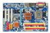
GA-946GZ-DS3 (rev. 2.0) Intel® CoreTM 2 Extreme quad-core / CoreTM 2 Quad / Intel® CoreTM 2 Extreme dual-core / CoreTM 2 Duo / Intel® Pentium® Processor Extreme Edition / Intel® Pentium® D / Pentium® 4 LGA775 Processor Motherboard User's Manual Rev. 2002 12ME-946GZDS3-2002R * The WEEE marking on the - Gigabyte GA-946GZ-DS3 | Manual - Page 2
Motherboard GA-946GZ-DS3 (rev. 2.0) Oct. 25, 2006 Motherboard GA-946GZ-DS3 (rev. 2.0) Oct. 25, 2006 - Gigabyte GA-946GZ-DS3 | Manual - Page 3
. „ For detailed product information and specifications, please carefully read the "Product User Manual". „ For detailed information related to Gigabyte's unique features, please go to the "Technology Guide" section on Gigabyte's website to read or download the information you need. For more product - Gigabyte GA-946GZ-DS3 | Manual - Page 4
Table of Contents ItemChecklist ...6 OptionalAccessories ...6 GA-946GZ-DS3 (rev. 2.0) Motherboard Layout 7 Block Diagram ...8 Chapter 1 Hardware Installation 9 18 Chapter 2 BIOS Setup 29 The Main Menu (For example: BIOS Ver.: F1a 30 2-1 Standard CMOS Features 32 2-2 Advanced BIOS Features 34 - Gigabyte GA-946GZ-DS3 | Manual - Page 5
Drivers 51 3-1 Install Chipset Drivers 51 3-2 SoftwareApplications 52 3-3 Driver CD Information 52 3-4 Hardware Information 53 3-5 Contact Us ...53 Chapter 4 Appendix 55 4-1 Unique Software Utilities 55 4-1-1 EasyTune 5 Introduction 55 4-1-2 Xpress Recovery2 Introduction 56 4-1-3 Flash BIOS - Gigabyte GA-946GZ-DS3 | Manual - Page 6
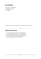
Item Checklist IDE Cable x 1, FDD Cable x 1 SATA 3Gb/s Cable x 2 I/O Shield * The items listed above are for reference only, and are subject to change without notice. Optional Accessories Š 2 Ports USB 2.0 Cable (Part Number: 12CR1-1UB030-51/R) Š 4 Ports USB 2.0 Cable (Part Number: 12CR1-1UB030-21 - Gigabyte GA-946GZ-DS3 | Manual - Page 7
Intel® 946GZ PCIE_3 PCIE_16 GA-946GZ-DS3 PWR_FAN ATX DDRII1 DDRII2 DDRII3 DDRII4 CODEC PCIE_1 PCIE_2 CI CD_IN FDD SPDIF_IO CLR_CMOS BATTERY Intel® ICH7 SYS _FAN PCI1 PCI2 BIOS SATAII0 SATAII2 SATAII1 SATAII3 PCI3 IDE1 F_USB2 F_PANEL F_USB1 PWR_LED - 7 - REV: 2.0 IT8718 - Gigabyte GA-946GZ-DS3 | Manual - Page 8
x1 x1 x1 PCIe CLK (100 MHz) 3 PCI Express x1 PCI Bus Host Interface Intel® 946GZ DDRII 667(Note)/533 MHz DIMM Dual Channel Memory GMCH CLK (266/200/133 MHz) BIOS ATA33/66/100 IDE Channel Intel® ICH7 4 SATA 3Gb/s Floppy IT8718 LPT Port COM Port 3 PCI CODEC 8 USB Ports PS/2 KB - Gigabyte GA-946GZ-DS3 | Manual - Page 9
circuits and components which can become damaged as a result of electrostatic discharge (ESD). Thus, prior to installation, please follow the instructions manual. 3. Before using the product, please verify that all cables steps or have a problem related to the use of in the user manual. 3. Damage due - Gigabyte GA-946GZ-DS3 | Manual - Page 10
fan connector Š 1 front panel connector Š 1 front audio connector Š 1 CD In connector Š 1 S/PDIF In/Out connector Š 2 USB 2.0/1.1 connectors for additional 4 USB 2.0/1.1 ports by cables Š 1 power LED connector Š 1 Chassis Intrusion connector GA-946GZ-DS3 (rev. 2.0) Motherboard - 10 - - Gigabyte GA-946GZ-DS3 | Manual - Page 11
(Line In / Line Out speed detection Š CPU warning temperature Š CPU / System / Power fan failure warning Š Supports CPU Smart Fan function BIOS Š 1 4 Mbit flash ROM Š Use of licensed AWARD BIOS Additional Features Š Supports @BIOS Š Supports Download Center Š Supports Q-Flash Š Supports - Gigabyte GA-946GZ-DS3 | Manual - Page 12
Processor with HT Technology - Chipset: An Intel® Chipset that supports HT Technology - BIOS: A BIOS that supports HT Technology and has it enabled or bending motions that might cause damage to the CPU during installation.) GA-946GZ-DS3 (rev. 2.0) Motherboard - 12 - Fig. 4 Once the CPU is - Gigabyte GA-946GZ-DS3 | Manual - Page 13
diagonally. Fig. 4 Please make sure the Male and Female push pin are joined closely. (for detailed installation instructions, please refer to the CPU cooler installation section of the user manual) Fig. 5 Please check the back of motherboard after installing. If the push pin is inserted as the - Gigabyte GA-946GZ-DS3 | Manual - Page 14
are unable to insert the module, please switch the direction. The motherboard supports DDRII memory modules, whereby BIOS will automatically detect memory capacity and specifications. Memory modules are designed so when you wish to remove the DIMM module. GA-946GZ-DS3 (rev. 2.0) Motherboard - 14 - - Gigabyte GA-946GZ-DS3 | Manual - Page 15
English Dual Channel Memory Configuration GA-946GZ-DS3 supports the Dual Channel Technology. After operating the Dual Channel Technology, the bandwidth of Memory Bus will add double. GA-946GZ-DS3 includes 4 DIMM sockets, and each Channel has two DIMM sockets as following: Channel 0 : DDRII1, DDRII2 - Gigabyte GA-946GZ-DS3 | Manual - Page 16
Express x16 slot and press firmly down on the slot. Make sure your VGA card is locked by the latch at the end of the PCI Express x16 slot. When you try uninstall the VGA card, please gently press the latch as the picture to the left shows to release the card. GA-946GZ-DS3 (rev - Gigabyte GA-946GZ-DS3 | Manual - Page 17
. If your OS does not support USB controller, please contact OS vendor for possible patch or driver upgrade. For more information please contact your OS or device(s) vendors. LAN Port The provided Internet connection is Gigabit Ethernet, providing data transfer speeds of 10/100/ 1000Mbps. Center - Gigabyte GA-946GZ-DS3 | Manual - Page 18
1-7 Connectors Introduction 1 3 5 6 2 11 16 13 14 1) ATX_12V 2) ATX (Power Connector) 3) CPU_FAN 4) SYS_FAN 5) PWR_FAN 6) NB_FAN 7) IDE1 8) FDD 9) SATAII0 / 1 / 2 / 3 GA-946GZ-DS3 (rev. 2.0) Motherboard 17 18 9 4 7 12 8 15 10 10) PWR_LED 11) F_AUDIO 12) F_PANEL 13) CD_IN 14) SPDIF_IO 15 - Gigabyte GA-946GZ-DS3 | Manual - Page 19
+5V) +12V +12V(Only for 24-pin ATX) 3.3V(Only for 24-pin ATX) Pin No. 13 14 15 16 17 18 19 20 21 22 23 24 Definition 3.3V -12V GND PS_ON(soft On/Off) GND GND GND -5V +5V +5V +5V (Only for 24-pin ATX) GND(Only for 24 - Gigabyte GA-946GZ-DS3 | Manual - Page 20
Speed Control SYS_FAN/PWR_FAN: Pin No. 1 2 3 Definition GND +12V Sense 6) NB_FAN (Chip Fan Connector) If you installed wrong direction, the chip fan will not work. Sometimes will damage the chip fan. (Usually black cable is GND) Pin No. Definition 1 GND 1 2 +12V 3 NC GA-946GZ-DS3 (rev - Gigabyte GA-946GZ-DS3 | Manual - Page 21
settings, please refer to the instructions located on the IDE device). Before attaching the IDE cable, please take note of cable while the other end of the cable connects to the FDD drive. The types of FDD drives supported are: 360KB, 720KB, 1.2MB, 1.44MB and 2.88MB. Before attaching the FDD cable - Gigabyte GA-946GZ-DS3 | Manual - Page 22
to the BIOS setting for the SATA 3Gb/s and install the proper driver in order to work properly. SATAII0 7 17 SATAII2 1 1 71 7 SATAII1 SATAII3 Pin No. 1 2 3 4 5 6 7 Definition GND TXP mode(S1). Pin No. Definition 1 MPD+ 1 2 MPD- 3 MPD- GA-946GZ-DS3 (rev. 2.0) Motherboard - 22 - - Gigabyte GA-946GZ-DS3 | Manual - Page 23
: Pin No. Definition 1 MIC 2 GND 3 MIC Power 4 NC 5 Line Out (R) 6 NC 7 NC 8 No Pin 9 Line Out (L) 10 NC By default, the audio driver is configured to support HD Audio. To connect an AC97 front panel audio module to this connector, please refer to the instructions on Page 71 - Gigabyte GA-946GZ-DS3 | Manual - Page 24
. Message LED/ Power/ Sleep LED Speaker Connector Power Switch MSG+ MSG- PW+ PWSPEAK+ SPEAK- 2 20 1 19 HD+ HD- RESRES+ NC HD (IDE Hard Disk Active LED) (Blue) SPEAK (Speaker Close: Power On/Off Pin 1: LED anode(+) Pin 2: LED cathode(-) NC GA-946GZ-DS3 (rev. 2.0) Motherboard - 24 - - Gigabyte GA-946GZ-DS3 | Manual - Page 25
assignment carefully while you connect the S/PDIF cable, incorrect connection between the cable and connector will make the device unable to work or even damage it. For optional S/PDIF cable, please contact your local dealer. 26 15 Pin No. 1 2 3 4 5 6 Definition Power No Pin SPDIF SPDIFI GND GND - Gigabyte GA-946GZ-DS3 | Manual - Page 26
work or even damage it. For optional front USB cable, please contact your local dealer. 2 10 1 9 Pin No. 1 2 3 4 5 6 7 8 9 10 Definition Power (5V) Power (5V) USB DXUSB DyUSB DX Opened" status in BIOS Setup. Pin No. Definition 1 1 Signal 2 GND GA-946GZ-DS3 (rev. 2.0) Motherboard - 26 - - Gigabyte GA-946GZ-DS3 | Manual - Page 27
is incorrectly replaced. Replace only with the same or equivalent type recommended by the manufacturer. Dispose of used batteries according to the manufacturer's instructions. If you want to erase CMOS... 1. Turn off the computer and unplug the power cord. 2. Gently take out the battery and put it - Gigabyte GA-946GZ-DS3 | Manual - Page 28
English GA-946GZ-DS3 (rev. 2.0) Motherboard - 28 - - Gigabyte GA-946GZ-DS3 | Manual - Page 29
BIOS, either Gigabyte's Q-Flash or @BIOS utility can be used. Q-Flash allows the user to quickly and easily update or backup BIOS without entering the operating system. @BIOS CMOS changes, only for Main Menu Main Menu The on-line description of the highlighted setup function is displayed at the - Gigabyte GA-946GZ-DS3 | Manual - Page 30
when somehow the system is not stable as usual. This action makes the system reset to the default settings for stability. 3. The BIOS Setup menus described in this chapter are for reference only and may differ from the exact settings for your motherboard. GA-946GZ-DS3 (rev. 2.0) Motherboard - 30 - - Gigabyte GA-946GZ-DS3 | Manual - Page 31
setup page includes all the items in standard compatible BIOS. „ Advanced BIOS Features This setup page includes all the items of Status This setup page is the System auto detect Temperature, voltage, fan, speed. „ MB Intelligent Tweaker(M.I.T.) This setup page is control CPU clock and frequency - Gigabyte GA-946GZ-DS3 | Manual - Page 32
Drive A Floppy 3 Mode Support Halt On Base Memory Manual User can manually BIOS to automatically detect IDE/SATA devices during POST(default) Select this if no IDE/SATA devices are used and the system will skip the automatic detection step and allow for faster system start up. GA-946GZ-DS3 (rev - Gigabyte GA-946GZ-DS3 | Manual - Page 33
3.5" 3.5 inch double-sided drive; 2.88M byte capacity. Floppy 3 Mode Support (for Japan Area) Disabled Normal Floppy Drive. (Default value) Drive A that may be detected and you All Errors will be prompted. Whenever the BIOS detects a non-fatal error the system will be stopped. All, But - Gigabyte GA-946GZ-DS3 | Manual - Page 34
CMOS Setup Utility-Copyright (C) 1984-2006 Award Software Advanced BIOS Features ` Hard Disk Boot Priority First Boot Device Second Boot Device Third Boot empty. (Note) This item will show up when you install a processor which supports this function. GA-946GZ-DS3 (rev. 2.0) Motherboard - 34 - - Gigabyte GA-946GZ-DS3 | Manual - Page 35
VGA card on the motherboard. PEG Set Init display first to PCI Express VGA card. PCI Set Init display first to PCI. (Default value) Onboard Set Init display first to Onboard VGA. (Note) This item will show up when you install a processor which supports this function. - 35 - BIOS Setup - Gigabyte GA-946GZ-DS3 | Manual - Page 36
Express VGA card is installed. (Default value) Always Enable Always activate the onboard VGA first, whether or not a PCI Express Disable this function. Auto BIOS will auto detect. ( Support a maximum of 4 SATA devices. PATA devices will be ignored. GA-946GZ-DS3 (rev. 2.0) Motherboard - 36 - - Gigabyte GA-946GZ-DS3 | Manual - Page 37
) USB Mouse Support Enabled Enable USB Mouse Support. Disabled Disable USB Mouse Support. (Default value) Legacy USB storage detect This option allows users to decide whether to detect USB storage devices, including USB flash drives and USB hard drives during POST. Enabled BIOS will scan - Gigabyte GA-946GZ-DS3 | Manual - Page 38
mode; it will operate at a normal speed of 10/100/1000Mbps in Windows mode or when the LAN Boot ROM is activated. When a Cable Problem Occurs... If a cable problem occurs on a specified pair of wires, is the approximate length of the attached LAN cable. GA-946GZ-DS3 (rev. 2.0) Motherboard - 38 - - Gigabyte GA-946GZ-DS3 | Manual - Page 39
3E8/IRQ4 Enable onboard Serial port 1 and address is 3E8/IRQ4. 2E8/IRQ3 Auto Enable onboard Serial port 1 and address is 2E8/IRQ3. BIOS will automatically setup the port 1 address. Onboard Parallel Port Disabled Disable onboard LPT port. 378/IRQ7 278/IRQ5 Enable onboard LPT port and address - Gigabyte GA-946GZ-DS3 | Manual - Page 40
) : (0~59) Power On By Mouse Disabled Disable this function. (Default value) Double Click Double click on PS/2 mouse left button to power on the system. GA-946GZ-DS3 (rev. 2.0) Motherboard - 40 - - Gigabyte GA-946GZ-DS3 | Manual - Page 41
3 IRQ Assignment Auto Auto assign IRQ to PCI 3. (Default value) 3,4,5,7,9,10,11,12,14,15 Set IRQ 3,4,5,7,9,10,11,12,14,15 to PCI 3. - 41 - BIOS Setup - Gigabyte GA-946GZ-DS3 | Manual - Page 42
+12V Current System Temperature Current CPU Temperature Current CPU FAN Speed Current SYSTEM FAN Speed Current POWER FAN Speed CPU Warning Temperature CPU FAN Fail Warning SYSTEM FAN Fail Warning . (Default value) Enable the fan fail warning function. GA-946GZ-DS3 (rev. 2.0) Motherboard - 42 - - Gigabyte GA-946GZ-DS3 | Manual - Page 43
In fact, the Voltage option can be used for CPU fans with 3-pin or 4-pin power cables. However, some 4-pin CPU fan power cables are not designed following Intel 4-Wire fans PWM control specifications. With such CPU fans, selecting PWM will not effectively reduce the fan speed. - 43 - BIOS Setup - Gigabyte GA-946GZ-DS3 | Manual - Page 44
. Doing a overclock or overvoltage on CPU, chipsets and memory modules may result in damages or Booster Select the options can enhance the VGA graphics card bandwidth to get higher performance. Auto Set Robust Graphics Booster supports this function. GA-946GZ-DS3 (rev. 2.0) Motherboard - 44 - - Gigabyte GA-946GZ-DS3 | Manual - Page 45
frequency automatically. (Default value) 90~150 Set PCI Express frequency from 90 MHz to 150 MHz. C.I.A.2 C.I.A.2 (CPU Intelligent Acelerator 2) is designed to detect CPU loading Control to +0.3V. Incorrect using it may cause your system broken. For power End-User use only! - 45 - BIOS Setup - Gigabyte GA-946GZ-DS3 | Manual - Page 46
Control to +0.2V. +0.3V Set (G)MCH OverVoltage Control to +0.3V. CPU Voltage Control Supports adjustable CPU Vcore. The adjustable range is dependent on CPUs. (Default value: Normal) Please occur. Normal CPU Vcore Display your CPU Vcore Voltage. GA-946GZ-DS3 (rev. 2.0) Motherboard - 46 - - Gigabyte GA-946GZ-DS3 | Manual - Page 47
Software ` Standard CMOS Features Load Fail-Safe Defaults ` Advanced BIOS Features Load Optimized Defaults ` Integrated Peripherals Set Supervisor Password Defaults Selecting this field loads the factory defaults for BIOS and Chipset Features which the system automatically detects. - 47 - Gigabyte GA-946GZ-DS3 | Manual - Page 48
BIOS Features Menu, you will be prompted for the password every time the system is rebooted or any time you try to enter Setup Menu. If you select "Setup" at "Password Check" in Advance BIOS Features Menu, you will be prompted only when you try to enter Setup. GA-946GZ-DS3 (rev. 2.0) Motherboard - Gigabyte GA-946GZ-DS3 | Manual - Page 49
2-11 Save & Exit Setup CMOS Setup Utility-Copyright (C) 1984-2006 Award Software ` Standard CMOS Features Load Fail-Safe Defaults ` Advanced BIOS Features Load Optimized Defaults ` Integrated Peripherals Set Supervisor Password ` Power Management Setup Save to CMOS and EXIT (SYe/tNU)?seYr - Gigabyte GA-946GZ-DS3 | Manual - Page 50
English GA-946GZ-DS3 (rev. 2.0) Motherboard - 50 - - Gigabyte GA-946GZ-DS3 | Manual - Page 51
will continue to install other drivers. System will reboot automatically after install the drivers, afterward you can install others application. For USB2.0 driver support under Windows XP operating system, please use Windows Service Pack. After install Windows Service Pack, it will show a question - Gigabyte GA-946GZ-DS3 | Manual - Page 52
This page displays all the tools that Gigabyte developed and some free software, you can choose anyone you want and press "install" to install them. 3-3 Driver CD Information This page lists the contents of software and drivers in this CD-title. GA-946GZ-DS3 (rev. 2.0) Motherboard - 52 - - Gigabyte GA-946GZ-DS3 | Manual - Page 53
English 3-4 Hardware Information This page lists all device you have for this motherboard. 3-5 Contact Us Please see the last page for details. - 53 - Install Drivers - Gigabyte GA-946GZ-DS3 | Manual - Page 54
English GA-946GZ-DS3 (rev. 2.0) Motherboard - 54 - - Gigabyte GA-946GZ-DS3 | Manual - Page 55
model support tools such as 1) Overclocking for enhancing system performance, 2) C.I.A. and M.I.B. for special enhancement for CPU and Memory, 3) Smart-Fan control for managing fan speed control of both CPU cooling fan and North-Bridge Chipset status 9. GIGABYTE Logo Log on to GIGABYTE website 10 - Gigabyte GA-946GZ-DS3 | Manual - Page 56
bytes of system memory 3. VESA-supported VGA cards How to use the speed of the hard disk will affect the data backup speed. 3. It is recommended that Xpress Recovery2 be immediately installed once you complete installations of OS and all required drivers as well as software. GA-946GZ-DS3 (rev - Gigabyte GA-946GZ-DS3 | Manual - Page 57
5. USB hard disks are currently not supported. 6. Does not support RAID/AHCI (class code 0104/0106) hard sure to execute the EnableBigLba.exe program from the driver CD before data backup. 2. It is normal a few motherboards based on Nvidia chipsets, BIOS update is required for Xpress Recovery2 - Gigabyte GA-946GZ-DS3 | Manual - Page 58
Primary Master : FUJITSU MPE3170AT ED-03-08 Primary Slave : None Secondary Master : CREATIVEDVD-RM DVD1242E BC101 Secondary Slave : None Press DEL to enter SETUP / Dual BIOS / Q-Flash / F9 For Xpress Recovery 08/07/2003-i875P-6A79BG03C-00 GA-946GZ-DS3 (rev. 2.0) Motherboard - 58 - - Gigabyte GA-946GZ-DS3 | Manual - Page 59
Backup Load Default Settings Save Settings to CMOS Q-Flash Utility Load Main BIOS from Floppy Load Backup BIOS from Floppy Save Main BIOS to Floppy Save Backup BIOS to Floppy Enter : Run :Move ESC:Reset F10:Power Off Dual BIOS utility bar Q-FlashTM utility title bar Action bar Task menu for - Gigabyte GA-946GZ-DS3 | Manual - Page 60
BIOS from Floppy Save Main BIOS to Floppy Save Backup BIOS to Floppy Enter : Run :Move ESC:Reset F10:Power Off Do not turn off power or reset your system at this stage!! After BIOS file is read, you'll see a confirmation dialog box asking you "Are you sure to update BIOS?" GA-946GZ-DS3 (rev - Gigabyte GA-946GZ-DS3 | Manual - Page 61
Disable CPolpeyasMe apirneRssOaMnyDkaetya to cBoanctkiunpue Load Default Settings Save Settings to CMOS Q-Flash Utility Load Main BIOS from Floppy Load Backup BIOS from Floppy Save Main BIOS to Floppy Save Backup BIOS to Floppy Enter : Run :Move ESC:Reset F10:Power Off You can repeat Step 1 to - Gigabyte GA-946GZ-DS3 | Manual - Page 62
and exit. Part Two: Updating BIOS with Q-FlashTM Utility on Single-BIOS Motherboards. This part guides users of single-BIOS motherboards how to update BIOS using the Q-FlashTM utility. CMOS Setup Item F10: Save & Exit Setup Time, Date, Hard Disk Type... GA-946GZ-DS3 (rev. 2.0) Motherboard - 62 - - Gigabyte GA-946GZ-DS3 | Manual - Page 63
V1.30 Flash Type/Size SST 49LF003A 256K Q-FlashTM utility bar Task menu for Q-FlashTM utility Enter : Run Keep DMI Data Enable Update BIOS from Floppy Save BIOS to Floppy :Move ESC:Reset F10:Power Off Action bar Task menu for Q-Flash utility: Contains the names of three tasks. Blocking - Gigabyte GA-946GZ-DS3 | Manual - Page 64
/2003-I845GE-6A69YG01C-00 6. Press Del to enter BIOS menu after system reboots and load BIOS optimized defaults. See how to load BIOS optimized defaults, please kindly refer to Step 6 to 7 in Part One. Congratulation!! You have updated BIOS successfully!! GA-946GZ-DS3 (rev. 2.0) Motherboard - 64 - - Gigabyte GA-946GZ-DS3 | Manual - Page 65
Fig 2. Installation Complete and Run @BIOS Select @BIOS item than click Install Fig 3. The @BIOS Utility Click "3" Click "Update New BIOS" Click Start/ Programs/ GIGABYTE/@BIOS Fig 4. Select the desired @BIOS server 1. Methods and steps: I. Update BIOS through Internet a. Click "Internet Update - Gigabyte GA-946GZ-DS3 | Manual - Page 66
, please go onto Gigabyte's web site for downloading and updating it according to method II. IV. Please note that any interruption during updating will cause system unbooted. V. Do not use @BIOS and C.O.M. (Corporate Online Management) at the same time. GA-946GZ-DS3 (rev. 2.0) Motherboard - 66 - Gigabyte GA-946GZ-DS3 | Manual - Page 67
Line Out (Front Speaker Out) Mic In Note that if you wish to connect a microphone, you MUST connect it to the default Mic In jack for the microphone to work correctly. HD Audio With multiple built-in high quality digital-to-analog converters (DACs) that support of the audio driver, you should find - Gigabyte GA-946GZ-DS3 | Manual - Page 68
the audio driver, you should find an Audio Manager icon in your system tray (you can also find the icon in Control Panel). Doubleclick the icon to open the Audio Control Panel. STEP 2: In the Audio Control Panel, click the Audio I/O tab. In the upper left list, click 4CH Speaker. GA-946GZ-DS3 (rev - Gigabyte GA-946GZ-DS3 | Manual - Page 69
on the type of speaker connected (4-channel audio consists of Front Speaker Out (Line Out) and Rear Speaker Out) and then click OK. The 4-channel is completed. 6 Channel Audio Setup STEP 1 : After installation of the audio driver, you should find an Audio Manager icon in your system tray (you can - Gigabyte GA-946GZ-DS3 | Manual - Page 70
Audio Setup STEP 1 : After installation of the audio driver, you should find an Audio Manager icon in your Speaker Out (Line Out), Rear Speaker Out, Center/Subwoofer Speaker Out, and Side Speaker Out) then click OK. The 8-channel audio setup is completed. GA-946GZ-DS3 (rev. 2.0) Motherboard - Gigabyte GA-946GZ-DS3 | Manual - Page 71
as desired. AC'97 Audio Configuration: To enable the front panel audio connector to support AC97 Audio mode, go to the Audio Control Panel and click the Audio I/O tab. In the ANALOG area, click the Tool icon and then select the Disable front panel jack detection check box. This action completes - Gigabyte GA-946GZ-DS3 | Manual - Page 72
successfully 2 short: CMOS setting error 1 long 1 short: DRAM or M/B error 1 long 2 short: Monitor or display card error 1 long 3 short: Keyboard error 1 long 9 short: BIOS ROM error Continuous long beeps: DRAM error Continuous short beeps: Power error GA-946GZ-DS3 (rev. 2.0) Motherboard - 72 - - Gigabyte GA-946GZ-DS3 | Manual - Page 73
- 73 - Appendix English - Gigabyte GA-946GZ-DS3 | Manual - Page 74
English GA-946GZ-DS3 (rev. 2.0) Motherboard - 74 - - Gigabyte GA-946GZ-DS3 | Manual - Page 75
- 75 - Appendix English - Gigabyte GA-946GZ-DS3 | Manual - Page 76
English GA-946GZ-DS3 (rev. 2.0) Motherboard - 76 - - Gigabyte GA-946GZ-DS3 | Manual - Page 77
- 77 - Appendix English - Gigabyte GA-946GZ-DS3 | Manual - Page 78
: +86-29-85531943 FAX: +86-29-85539821 Shenyang TEL: +86-24-83992901 FAX: +86-24-83992909 y India GIGABYTE TECHNOLOGY (INDIA) LIMITED WEB address : http://www.gigabyte.in y Australia GIGABYTE TECHNOLOGY PTY. LTD. WEB address : http://www.gigabyte.com.au GA-946GZ-DS3 (rev. 2.0) Motherboard - 78 - - Gigabyte GA-946GZ-DS3 | Manual - Page 79
BYTE Technology Co., Ltd. in SERBIA & MONTENEGRO WEB address : http://www.gigabyte.co.yu y GIGABYTE Global Service System To submit a technical or non-technical (Sales/ Marketing) question, please link to : http://ggts.gigabyte.com.tw Then select your language to enter the system. - 79 - Appendix - Gigabyte GA-946GZ-DS3 | Manual - Page 80
- 80 -
-
 1
1 -
 2
2 -
 3
3 -
 4
4 -
 5
5 -
 6
6 -
 7
7 -
8
-
9
-
10
-
11
-
12
-
13
-
14
-
15
-
16
-
17
-
18
-
19
-
20
-
21
-
22
-
23
-
24
-
25
-
26
-
27
-
28
-
29
-
30
-
31
-
32
-
33
-
34
-
35
-
36
-
37
-
38
-
39
-
40
-
41
-
42
-
43
-
44
-
45
-
46
-
47
-
48
-
49
-
50
-
51
-
52
-
53
-
54
-
55
-
56
-
57
-
58
-
59
-
60
-
61
-
62
-
63
-
64
-
65
-
66
-
67
-
68
-
69
-
70
-
71
-
72
-
73
-
74
-
75
-
76
-
77
-
78
-
79
-
80
 |
 |

GA-946GZ-DS3
(rev. 2.0)
Intel
®
Core
TM
2 Extreme quad-core / Core
TM
2 Quad /
Intel
®
Core
TM
2 Extreme dual-core / Core
TM
2 Duo /
Intel
®
Pentium
®
Processor Extreme Edition /
Intel
®
Pentium
®
D / Pentium
®
4 LGA775 Processor Motherboard
User's Manual
Rev. 200
2
12ME-946GZDS3-200
2
R
*
The WEEE marking on the product indicates this product must not be disposed of with user's other household waste
and must be handed over to a designated collection point for the recycling of waste electrical and electronic equipment!!
*
The WEEE marking applies only in European Union's member states.