Gigabyte GA-965G-DS3 Manual
Gigabyte GA-965G-DS3 Manual
 |
View all Gigabyte GA-965G-DS3 manuals
Add to My Manuals
Save this manual to your list of manuals |
Gigabyte GA-965G-DS3 manual content summary:
- Gigabyte GA-965G-DS3 | Manual - Page 1
GA-965G-DS3 Intel® CoreTM 2 Extreme quad-core / CoreTM 2 Quad / Intel® CoreTM 2 Extreme dual-core / CoreTM 2 Duo / Intel® Pentium® Processor Extreme Edition / Intel® Pentium® D / Pentium® 4 LGA775 Processor Motherboard User's Manual Rev. 3301 12ME-I65GDS3-3301R * The WEEE marking on the product - Gigabyte GA-965G-DS3 | Manual - Page 2
Motherboard GA-965G-DS3 Oct. 20, 2006 Motherboard GA-965G-DS3 Oct. 20, 2006 - Gigabyte GA-965G-DS3 | Manual - Page 3
product information and specifications, please carefully read the "Product User Manual". „ For detailed information related to Gigabyte's unique features, please go to "Technology Guide" section on Gigabyte's website to read or download the information you need. For more product details, please - Gigabyte GA-965G-DS3 | Manual - Page 4
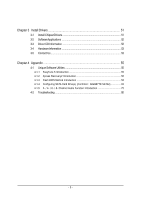
OptionalAccessories ...6 GA-965G-DS3 Motherboard Layout 7 Block Diagram ...8 Chapter 1 Hardware Installation 9 1-1 Considerations Prior to Installation 9 1-2 Feature Summary 10 1-3 Installation of the CPU and CPU Cooler 12 1-3-1 Installation of the CPU 12 1-3-2 Installation of the CPU Cooler - Gigabyte GA-965G-DS3 | Manual - Page 5
Software Utilities 55 4-1-1 EasyTune 5 Introduction 55 4-1-2 Xpress Recovery2 Introduction 56 4-1-3 Flash BIOS Method Introduction 58 4-1-4 Configuring SATA Hard Drive(s) (Controller: GIGABYTE SATA2 62 4-1-5 2- / 4- / 6- / 8- Channel Audio Function Introduction 75 4-2 Troubleshooting 80 - 5 - - Gigabyte GA-965G-DS3 | Manual - Page 6
Checklist IDE Cable x 1 and FDD Cable x 1 SATA 3Gb/s Cable x 4 I/O Shield * The items listed above are for reference only, and are subject to change without notice. Optional Accessories Š 2 Ports USB 2.0 Cable (Part Number: 12CR1-1UB030-51/R) Š 4 Ports USB 2.0 Cable (Part Number: 12CR1-1UB030-21 - Gigabyte GA-965G-DS3 | Manual - Page 7
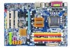
CPU_FAN ATX GA-965G-DS3 USB USB LAN SYS_FAN F_AUDIO AUDIO Intel® G965 NB_FAN DDRII1 PCIE_3 FDD Marvell 88E8056 PCIE_16 DDRII3 DDRII4 PWR_FAN DDRII2 PCIE_1 CODEC PCIE_2 PCI1 PCI2 IT8718 PCI3 CD_IN CLR_CMOS BATTERY Intel® ICH8 GSATAII0 GIGABYTE SATA2 GSATAII1 BIOS IDE1 CI - Gigabyte GA-965G-DS3 | Manual - Page 8
x1 x1 PCIe CLK (100 MHz) 3 PCI Express x1 PCI Bus LGA775 Processor CPU CLK+/-(266/200/133 MHz) Host Interface DDRII 800/667/533 MHz DIMM(Note) Intel® G965 Dual Channel Memory GMCH CLK (266/200/133 MHz) Intel® ICH8 CODEC BIOS 4 SATA 3Gb/s 10 USB Ports IT8718 LPT Floppy COM Port PS/2 KB - Gigabyte GA-965G-DS3 | Manual - Page 9
instructions below: 1. Please turn off the computer and unplug its power cord. 2. When handling the motherboard , avoid touching any metal leads or connectors. 3. It is best to wear an electrostatic discharge (ESD) cuff when handling electronic components (CPU, RAM motherboard problem manual - Gigabyte GA-965G-DS3 | Manual - Page 10
Duo / Pentium® processor Extreme Edition / Pentium® D / Pentium® 4 / Celeron® D Š L2 cache varies with CPU Front Side Bus Š Supports 1066/800/533 MHz FSB Chipset Š Northbridge: Intel® G965 Express Chipset Š Southbridge: Intel® ICH8 LAN Š Onboard Marvell 88E8056 phy (10/100/1000 Mbit) Audio - Gigabyte GA-965G-DS3 | Manual - Page 11
warning Š CPU Smart Fan Control BIOS Š 1 8 Mbit flash ROM Š Use of licensed AWARD BIOS Š PnP 1.0a, DMI 2.0, SM BIOS 2.3, ACPI 1.0b Additional Features Š Supports @BIOS Š Supports Download Center Š Supports Q-Flash Š Supports EasyTune (Note 2) Š Supports Xpress Install Š Supports Xpress - Gigabyte GA-965G-DS3 | Manual - Page 12
your thumb and forefinger, carefully place it into the socket in a straight and downwards motion. Avoid twisting or bending motions that might cause damage to the CPU during installation.) GA-965G-DS3 Motherboard - 12 - Fig. 4 Once the CPU is properly inserted, please replace the load plate and - Gigabyte GA-965G-DS3 | Manual - Page 13
instruction is only for Intel boxed fan) Fig. 3 Place the CPU cooler atop the CPU and make sure the push pins aim to the pin hole on the motherboard installation instructions, please refer to the CPU cooler installation section of the user manual) Fig. 5 Please check the back of motherboard after - Gigabyte GA-965G-DS3 | Manual - Page 14
fit in one direction. Insert the DIMM memory module vertically into the DIMM socket. Then push it down. Fig.2 Close the plastic clip at both edges of the DIMM sockets to lock the DIMM module. Reverse the installation steps when you wish to remove the DIMM module. GA-965G-DS3 Motherboard - 14 - - Gigabyte GA-965G-DS3 | Manual - Page 15
memory bus will double. The GA-965G-DS3 includes 4 DIMM sockets, and each Channel has two DIMM sockets as following: Channel 0 : DDRII1, DDRII2 Channel 1 : DDRII3, DDRII4 If you want to operate the Dual Channel Technology, please note the following explanations due to the limitation of Intel chipset - Gigabyte GA-965G-DS3 | Manual - Page 16
Express x16 slot and press firmly down on the slot. Make sure your VGA card is locked by the latch at the end of the PCI Express x16 slot. When you try uninstall the VGA card, please gently press the latch as the picture to the left shows to release the card. GA-965G-DS3 Motherboard - Gigabyte GA-965G-DS3 | Manual - Page 17
sure your OS supports USB controller. If your OS does not support USB controller, please contact OS vendor for possible patch or driver upgrade. For more information please contact your OS or device(s) vendors. LAN Port The provided Internet connection is Gigabit Ethernet, providing data transfer - Gigabyte GA-965G-DS3 | Manual - Page 18
5 20 10 12 9 15 16 17 1) ATX_12V 2) ATX (Power Connector) 3) CPU_FAN 4) SYS_FAN 5) PWR_FAN 6) NB_FAN 7) FDD 8) IDE1 9) SATAII0/1/2/3 10) GSATAII0/1 GA-965G-DS3 Motherboard 18 8 19 11 13 11) PWR_LED 12) BATTERY 13) F_PANEL 14) F_AUDIO 15) CD_IN 16) SPDIF_I 17) COMA 18) F_USB1 / F_USB2 - Gigabyte GA-965G-DS3 | Manual - Page 19
the power connector, please make sure that all components and devices are properly installed. Align the power connector with its proper location on the motherboard and connect tightly. The ATX_12V power connector mainly supplies power to the CPU. If the ATX_12V power connector is not connected, the - Gigabyte GA-965G-DS3 | Manual - Page 20
wire is the ground wire (GND). Remember to connect the CPU/system/power fan cable to the CPU_FAN/SYS_FAN/PWR_FAN connector to prevent CPU damage or system hanging caused by overheating. 1 CPU_FAN 1 is GND) NB_FAN : Pin No. Definition 1 1 GND 2 +12V 3 NC GA-965G-DS3 Motherboard - 20 - - Gigabyte GA-965G-DS3 | Manual - Page 21
(hard drive or optical drive). If you wish to connect two IDE devices, please set the jumper on one IDE device as Master and the other as Slave (for information on settings, please refer to the instructions located on the IDE device). Before attaching the IDE cable, please take note of the foolproof - Gigabyte GA-965G-DS3 | Manual - Page 22
by GIGABYTE SATA2) SATA 3Gb/s can provide up to 300 MB/s transfer rate. Please refer to the BIOS setting for the Serial ATA and install the proper driver in order to work properly. 7 1 GSATAII0 GSATAII1 1 7 Pin No. 1 2 3 4 5 6 7 Definition GND TXP TXN GND RXN RXP GND GA-965G-DS3 Motherboard - Gigabyte GA-965G-DS3 | Manual - Page 23
is incorrectly replaced. Replace only with the same or equivalent type recommended by the manufacturer. Dispose of used batteries according to the manufacturer's instructions. If you want to erase CMOS... 1. Turn off the computer and unplug the power cord. 2. Gently take out the battery and put it - Gigabyte GA-965G-DS3 | Manual - Page 24
1: Power Pin 2- Pin 3: NC Pin 4: Data(-) Open: Normal Close: Reset Hardware System Open: Normal Close: Power On/Off Pin 1: LED anode(+) Pin 2: LED cathode(-) NC GA-965G-DS3 Motherboard - 24 - - Gigabyte GA-965G-DS3 | Manual - Page 25
Pin 8 No Pin 9 LINE2_L 9 Line Out (L) 10 FSENSE2 10 NC By default, the audio driver is configured to support HD Audio. To connect an AC97 front panel audio module to this connector, please refer to the instructions on Page 79 about the software settings. 15) CD_IN (CD IN) Connect CD-ROM - Gigabyte GA-965G-DS3 | Manual - Page 26
connect the S/PDIF cable, incorrect connection between the cable and connector will make the device unable to work or even damage it. For optional S/PDIF cable, please contact No. 1 2 3 4 5 6 7 8 9 10 Definition NDCDANSINA NSOUTA NDTRAGND NDSRANRTSANCTSANRIANo Pin GA-965G-DS3 Motherboard - 26 - - Gigabyte GA-965G-DS3 | Manual - Page 27
connection between the cable and connector will make the device unable to work or even damage it. For optional front USB cable, please contact your local dealer. 9 1 10 2 Pin No. 1 2 3 4 5 6 7 8 9 10 Definition Power(5V) Power(5V) USB DXUSB DyUSB DX+ USB Dy+ GND GND No Pin NC 19) CI (Chassis - Gigabyte GA-965G-DS3 | Manual - Page 28
English 20) CLR_CMOS (Clear CMOS) You may clear the CMOS data to its default values by this header. To clear CMOS, temporarily short the two pins. Default doesn't include the jumper to avoid improper use of this header. Open: Normal Short: Clear CMOS GA-965G-DS3 Motherboard - 28 - - Gigabyte GA-965G-DS3 | Manual - Page 29
BIOS, either Gigabyte's Q-Flash or @BIOS utility can be used. Q-Flash allows the user to quickly and easily update or backup BIOS without entering the operating system. @BIOS is a Windows-based utility that does not require users to boot to DOS before upgrading BIOS but directly download and update - Gigabyte GA-965G-DS3 | Manual - Page 30
in the BIOS Setup when somehow the system is not stable as usual. This action makes the system reset to the default settings for stability. 3. The BIOS Setup menus described in this chapter are for reference only and may differ from the exact settings for your motherboard. GA-965G-DS3 Motherboard - Gigabyte GA-965G-DS3 | Manual - Page 31
This setup page includes all the items in standard compatible BIOS. „ Advanced BIOS Features This setup page includes all the items of voltage, fan, speed. „ MB Intelligent Tweaker(M.I.T.) This setup page is control CPU clock and frequency ratio. „ Load Fail-Safe Defaults Fail-Safe Defaults indicates - Gigabyte GA-965G-DS3 | Manual - Page 32
. You can use one of the two methods: • Auto Allows BIOS to automatically detect IDE/SATA devices during POST(default) • None Select this if no IDE/SATA devices are used and the system will skip the automatic detection step and allow for faster system start up. GA-965G-DS3 Motherboard - 32 - - Gigabyte GA-965G-DS3 | Manual - Page 33
capacity. Floppy 3 Mode Support (for Japan Area) memory installed on the motherboard. Extended Memory The BIOS determines how much extended memory is present during the POST. This is the amount of memory located above 1 MB in the CPU's memory address map. Total Memory This item displays the memory - Gigabyte GA-965G-DS3 | Manual - Page 34
BIOS Features Hard Disk Boot Priority First Boot Device Second Boot Device Third Boot Device Password Check HDD S.M.A.R.T. Capability CPU Hyper-Threading (Note) Limit CPUID Max. to 3 (Note) No-Execute Memory when you install a processor that supports this function. GA-965G-DS3 Motherboard - 34 - - Gigabyte GA-965G-DS3 | Manual - Page 35
with multi processors mode supported. (Default value) Disabled Disable CPU Hyper Threading. Limit CPUID Max. to 3 (Note) Enabled Disabled Limit CPUID Maximum value to 3 when use older OS like NT4. Disable CPUID Limit for windows XP. (Default value) No-Execute Memory Protect (Note) Enabled - Gigabyte GA-965G-DS3 | Manual - Page 36
from the onboard GPU when no PCI Express VGA card is installed. (Default value) Always Enable Always output from the onboard GPU. On-Chip Frame Buffer Size 8MB Set on-chip frame buffer size to 8MB. (Default value) 1MB Set on-chip frame buffer size to 1MB. GA-965G-DS3 Motherboard - 36 - - Gigabyte GA-965G-DS3 | Manual - Page 37
Award Software Integrated Peripherals SATA AHCI Mode SATA Port0-3 Native Mode USB Controller USB 2.0 Controller USB Keyboard Support USB Mouse Support Legacy USB storage detect Azalia Codec Onboard H/W LAN SMART LAN OnBoard LAN Boot ROM Onboard SATA/IDE Device Onboard SATA/IDE Ctrl Mode Onboard - Gigabyte GA-965G-DS3 | Manual - Page 38
Disabled BIOS will scan all USB storage devices. ( N/A,as shown in the figure above. 2. If no cable problem is detected on the LAN cable connected to a 10/100 motherboard, the Status fields of all four pairs of wires will show Open and the Length fields show 0.0m. GA-965G-DS3 Motherboard - 38 - - Gigabyte GA-965G-DS3 | Manual - Page 39
decide whether to invoke the boot ROM of the onboard LAN chip. Enabled Disabled Enable this function. Disable this function. (Default value) Onboard SATA/IDE Device This function allows users to enable or disable the SATA/IDE ports controlled by the GIGABYTE SATA2 controller. Enabled Enable - Gigabyte GA-965G-DS3 | Manual - Page 40
Alarm : Everyday, 1~31 Time (hh: mm: ss) Alarm : (0~23) : (0~59) : (0~59) HPET Support (Note) Disabled Disable this function. Enabled Enable support for High Precision Event Timer (HPET) funtion. (Default value) (Note) Supported on Vista operating system only. GA-965G-DS3 Motherboard - 40 - - Gigabyte GA-965G-DS3 | Manual - Page 41
characters) and press Enter to set the Keyboard Power On password. AC Back Function Soft-Off Full-On Memory When AC-power back to the system, the system will be in "Off" state. (Default value) Last state before AC-power off. (Note) Supported on Vista operating system only. - 41 - BIOS Setup - Gigabyte GA-965G-DS3 | Manual - Page 42
) Set IRQ 3,4,5,7,9,10,11,12,14,15 to PCI 2. Auto assign IRQ to PCI 3. (Default value) Set IRQ 3,4,5,7,9,10,11,12,14,15 to PCI 3. GA-965G-DS3 Motherboard - 42 - - Gigabyte GA-965G-DS3 | Manual - Page 43
Clear case open status at next boot. Case Opened If the case CPU temperature at 90oC / 194oF. Disable this function. (Default value) CPU/ SYSTEM/ POWER FAN Fail Warning Disabled Disable the fan fail warning function. (Default value) Enabled Enable the fan fail warning function. - 43 - BIOS - Gigabyte GA-965G-DS3 | Manual - Page 44
such CPU fans, selecting PWM will not effectively reduce the fan speed. (Note) Before setting this item to Intel(R) QST, make sure at least DDRII1 or DDRII2 socket in Channel 0 is populated. A small portion of system memory will be shared when Intel® QST is enabled. GA-965G-DS3 Motherboard - 44 - Gigabyte GA-965G-DS3 | Manual - Page 45
General Help F7: Optimized Defaults 1. Incorrectly using these features may result in system instability or corruption. Doing a overclock or overvoltage on CPU, chipsets and memory modules may result in damages or shortened life expectancy to these components. Please be aware that the M.I.T. menu - Gigabyte GA-965G-DS3 | Manual - Page 46
DRAM Timing configurations. If your system becomes unstable after you overclock the DDR2 memory, select Option 1 or Option 2 to help make your system more stable. Option 1 DRAM Timing Configuration 1. (Default value) Option 2 DRAM Timing Configuration 2. GA-965G-DS3 Motherboard - 46 - - Gigabyte GA-965G-DS3 | Manual - Page 47
requirements. Auto Lets the BIOS configure all system voltage settings. Manual Manually configure the system voltage settings. (Default value) DDR2 OverVoltage Control Please note that by overclocking your system through the increase of the DIMM voltage, damage to the memory may occur. Normal - Gigabyte GA-965G-DS3 | Manual - Page 48
Esc: Quit F8: Dual BIOS/Q-Flash : Select Item F10: Save & Exit Setup F11: Save CMOS to BIOS F12: Load CMOS from BIOS Load Optimized Defaults Selecting this field loads the factory defaults for BIOS and Chipset Features which the system automatically detects. GA-965G-DS3 Motherboard - 48 - - Gigabyte GA-965G-DS3 | Manual - Page 49
message "PASSWORD DISABLED" will appear to confirm the password being disabled. Once the password is disabled, the system will boot and you can enter Setup freely. The BIOS Setup program allows you to specify two separate passwords: SUPERVISOR PASSWORD and a USER PASSWORD. When disabled, anyone may - Gigabyte GA-965G-DS3 | Manual - Page 50
Safe Defaults Advanced BIOS Features Load Optimized BIOS/Q-Flash : Select Item F10: Save & Exit Setup F11: Save CMOS to BIOS F12: Load CMOS from BIOS Abandon all Data Type "Y" will quit the Setup Utility without saving to RTC CMOS. Type "N" will return to Setup Utility. GA-965G-DS3 Motherboard - Gigabyte GA-965G-DS3 | Manual - Page 51
shown in Windows XP. Insert the driver CD-title that came with your motherboard into your CD-ROM drive, the driver CD-title will auto start and show the installation guide. If not, please double click the CD-ROM device icon in "My computer", and execute the Run.exe. 3-1 Install Chipset Drivers After - Gigabyte GA-965G-DS3 | Manual - Page 52
Software Applications This page displays all the tools that Gigabyte developed and some free software, you can choose anyone you want and press "install" to install them. 3-3 Driver CD Information This page lists the contents of software and drivers in this CD-title. GA-965G-DS3 Motherboard - 52 - - Gigabyte GA-965G-DS3 | Manual - Page 53
English 3-4 Hardware Information This page lists all device you have for this motherboard. 3-5 Contact Us Please see the last page for details. - 53 - Install Drivers - Gigabyte GA-965G-DS3 | Manual - Page 54
English GA-965G-DS3 Motherboard - 54 - - Gigabyte GA-965G-DS3 | Manual - Page 55
yet easy to use tools such as 1) Overclocking for enhancing system performance, 2) C.I.A. and M.I.B. for special enhancement for CPU and Memory, 3) Smart-Fan control for managing fan speed control of both CPU cooling fan and North-Bridge Chipset cooling fan, 4) PC health for monitoring system status - Gigabyte GA-965G-DS3 | Manual - Page 56
disk data. Supporting Microsoft operating systems including Windows XP/2000/NT Intel G965 BIOS for 965G-DS3 F7a . . . . :BIOS Setup/Q-Flash :Xpress Recovery2 :Boot Menu :Qflash 01/11/2007-G965-ICH8-6A79LG09C-00 Boot drivers as well as software. GA-965G-DS3 Motherboard - 56 - - Gigabyte GA-965G-DS3 | Manual - Page 57
Windows 2000, be sure to execute the EnableBigLba.exe program from the driver CD before data backup. 2. It is normal that data backup takes longer time than data restoration. 3. Xpress Recovery2 is compliant with the GPL regulations. 4. On a few motherboards based on Nvidia chipsets, BIOS update - Gigabyte GA-965G-DS3 | Manual - Page 58
the BIOS update file is saved to a hard drive in RAID/AHCI mode or a hard drive attached to an independent IDE/SATA controller, use the End key during POST to access Q-Flash. Award Modular BIOS v6.00PG, An Energy Star Ally Copyright (C) 1984-2006, Award Software, Inc. Intel G965 BIOS for 965G-DS3 - Gigabyte GA-965G-DS3 | Manual - Page 59
press ENTER. Make sure again the BIOS file matches your motherboard model. Step 2: The process of system reading the BIOS file from the floppy disk is displayed on the screen. When the message "Are you sure to update BIOS?" appears, press ENTER. The BIOS update will begin and the current process - Gigabyte GA-965G-DS3 | Manual - Page 60
Update" icon b. Click "Update New BIOS" c. Please select "All Files" in dialog box while opening the old file. d. Please search for BIOS unzip file, downloading from internet or any other methods (such as: 965GDS3.F1). e. Complete update process following the instruction. GA-965G-DS3 Motherboard - Gigabyte GA-965G-DS3 | Manual - Page 61
II, be sure that motherboard's model name in BIOS unzip file are the same as your motherboard's. Otherwise, your system won't boot. III. In method I, if the BIOS file you need cannot be found in @BIOSTM server, please go onto Gigabyte's web site for downloading and updating it according to method - Gigabyte GA-965G-DS3 | Manual - Page 62
, refer to the connectors introduction section of the user's manual to identify the SATA controller for the connector. For example, on the GA-965G-DS3 motherboard, the GSATAII0 and GSATAII1 connectors are supported by the GIGABYTE SATA2 controller. Then connect the power connector from your power - Gigabyte GA-965G-DS3 | Manual - Page 63
Award Software Integrated Peripherals SATA AHCI Mode SATA Port0-3 Native Mode USB Controller USB 2.0 Controller USB Keyboard Support USB Mouse Support Legacy USB storage detect Azalia Codec Onboard H/W LAN SMART LAN OnBoard LAN Boot ROM Onboard SATA/IDE Device Onboard SATA/IDE Ctrl Mode Onboard - Gigabyte GA-965G-DS3 | Manual - Page 64
Ext PEG] [8MB] Item Help Menu Level Select Hard Disk Boot Device Priority : Move Enter: Select F5: Previous Values Step 3: Save and exit BIOS Setup. +/-/PU/PD: Value F10: Save F6: Fail-Safe Defaults Figure 2 ESC: Exit F1: General Help F7: Optimized Defaults GA-965G-DS3 Motherboard - 64 - - Gigabyte GA-965G-DS3 | Manual - Page 65
memory test begins and before the operating system boot begins, look for a message which says "Press to enter RAID Setup Utility" (Figure 3). Press CTRL+ G to enter the GIGABYTE RAID BIOS RAID [ RAID Disk Drive List ] [ TAB]-Switch Window [ ]-Select ITEM [ENTER]-Action Figure 4 [ESC]- - Gigabyte GA-965G-DS3 | Manual - Page 66
for the created RAID drive to be identified by system BIOS or OS. [ ]-Move Cursor [DEL,BS]-Delete Character (Figure 6). Then press ENTER to move onto the next step. GIGABYTE Technology Corp. PCIE-to-SATAII/IDE RAID Controller BIOSv1.06.53 [ GA-965G-DS3 Motherboard [ENTER]-Next Figure 6 - 66 - - Gigabyte GA-965G-DS3 | Manual - Page 67
selected, RAID BIOS automatically assigns the two hard disks installed as the RAID disks. 4. Set Block Size (only for RAID 0): Under the Block item, use the UP or DOWN ARROW key to select the block size (Figure 7), ranging from 4K to 128K. Press ENTER when finished. GIGABYTE Technology Corp. PCIE - Gigabyte GA-965G-DS3 | Manual - Page 68
new RAID array will be displayed in the RAID Disk Drive List block (Figure 10). GIGABYTE Technology Corp. PCIE-to-SATAII/IDE RAID Controller BIOSv1.06.53 [ Main Menu ] [ Members(HDDx) 01 [ TAB]-Switch Window [ ]-Select ITEM [ENTER]-Action Figure 10 [ESC]-Exit GA-965G-DS3 Motherboard - 68 - - Gigabyte GA-965G-DS3 | Manual - Page 69
Stripe Status: Norma2l40 GB Normal Members(HDDx) 01 [ TAB]-Switch Window [ ]-Select RAID [ENTER]-Detail Figure 11 [ESC]-Exit After to save your settings if you wish to exit the RAID BIOS utility, then press Y (Figure 12). GIGABYTE Technology Corp. PCIE-to-SATAII/IDE RAID Controller BIOSv1.06. - Gigabyte GA-965G-DS3 | Manual - Page 70
message (Figure 14) or N to cancel. GIGA-BYTE Technology Corp. PCIE-to-SATAII/IDE RAID Controller BIOS v1.06.53 [ Main Menu ] [ Hard Disk Drive List ] Create RAID Disk Drive Delete RAID Disk Select RAID [SPACE]-Mark Delete [DEL]-Confirm Figure 14 [ESC]-Abort GA-965G-DS3 Motherboard - 70 - - Gigabyte GA-965G-DS3 | Manual - Page 71
recognized during the Windows setup process. First of all, copy the driver for the SATA controller from the motherboard driver CD-ROM to a floppy disk. See the instructions below about how to copy the driver in MS-DOS mode(Note1). Prepare a startup disk that has CD-ROM support and a blank formatted - Gigabyte GA-965G-DS3 | Manual - Page 72
device manufacturer, press S. * If you do not have any device support disks from a mass storage device manufacturer, or do not want to specify additional mass storage devices for use with Windows, press ENTER. S=Specify Additional Device ENTER=Continue F3=Exit Figure 19 GA-965G-DS3 Motherboard - Gigabyte GA-965G-DS3 | Manual - Page 73
copy the correct SATA driver again from the motherboard driver CD. Step 4: When the next screen (Figure 21) appears, press ENTER to continue the SATA driver installation from the floppy disk. Windows Setup Setup will load support for the following mass storage device(s): GIGABYTE GBB36X Controller - Gigabyte GA-965G-DS3 | Manual - Page 74
installing Windows XP, press F3. Enter= Continue R=Repair F3=Exit Figure 22 (Note: Each time you add a new hard drive to a RAID array, the RAID driver will have to be installed under Windows once for that hard drive. After that, the driver will not have to be installed.) GA-965G-DS3 Motherboard - Gigabyte GA-965G-DS3 | Manual - Page 75
to install the function. (Following pictures are in Windows XP) Center/Subwoofer Speaker Out Rear Speaker Out quality digital-to-analog converters (DACs) that support audio output at up to 192 kHz/24- . STEP 1 : After installation of the audio driver, you should find an Audio Manager icon in - Gigabyte GA-965G-DS3 | Manual - Page 76
driver, you should find an Audio Manager icon in your system tray (you can also find the icon in Control Panel). Doubleclick the icon to open the Audio Control Panel. STEP 2: In the Audio Control Panel, click the Audio I/O tab. In the upper left list, click 4CH Speaker. GA-965G-DS3 Motherboard - Gigabyte GA-965G-DS3 | Manual - Page 77
left list, click 6CH Speaker. STEP 3: After plugging in 6-channel speakers to the rear speaker jacks, a small window will pop up and ask you what type of equipment is connected. Choose a device depending on the type of speaker connected (6-channel audio consists of Front Speaker Out (Line Out), Rear - Gigabyte GA-965G-DS3 | Manual - Page 78
equipment is connected. Choose a device depending on the type of speaker connected (8-channel audio consists of Front Speaker Out (Line Out), Rear Speaker Out, Center/Subwoofer Speaker Out, and Side Speaker Out) then click OK. The 8-channel audio setup is completed. GA-965G-DS3 Motherboard - 78 - - Gigabyte GA-965G-DS3 | Manual - Page 79
: At the Sound Effect menu, users can adjust sound option settings as desired. AC'97 Audio Configuration: To enable the front panel audio connector to support AC97 Audio mode, go to the Audio Control Panel and click the Audio I/O tab. In the ANALOG area, click the Tool icon and then select - Gigabyte GA-965G-DS3 | Manual - Page 80
: System boots successfully 2 short: CMOS setting error 1 long 1 short: DRAM or M/B error 1 long 2 short: Monitor or display card error 1 long 3 short: Keyboard error 1 long 9 short: BIOS ROM error Continuous long beeps: DRAM error Continuous short beeps: Power error GA-965G-DS3 Motherboard - 80 - Gigabyte GA-965G-DS3 | Manual - Page 81
- 81 - Appendix English - Gigabyte GA-965G-DS3 | Manual - Page 82
English GA-965G-DS3 Motherboard - 82 - - Gigabyte GA-965G-DS3 | Manual - Page 83
- 83 - Appendix English - Gigabyte GA-965G-DS3 | Manual - Page 84
English GA-965G-DS3 Motherboard - 84 - - Gigabyte GA-965G-DS3 | Manual - Page 85
- 85 - Appendix English - Gigabyte GA-965G-DS3 | Manual - Page 86
. 814 Xian TEL: +86-29-85531943 FAX: +86-29-85539821 Shenyang TEL: +86-24-83992901 FAX: +86-24-83992909 y India GIGABYTE TECHNOLOGY (INDIA) LIMITED WEB address : http://www.gigabyte.in y Australia GIGABYTE TECHNOLOGY PTY. LTD. WEB address : http://www.gigabyte.com.au GA-965G-DS3 Motherboard - 86 - - Gigabyte GA-965G-DS3 | Manual - Page 87
BYTE Technology Co., Ltd. in SERBIA & MONTENEGRO WEB address : http://www.gigabyte.co.yu y GIGABYTE Global Service System To submit a technical or non-technical (Sales/ Marketing) question, please link to : http://ggts.gigabyte.com.tw Then select your language to enter the system. - 87 - Appendix - Gigabyte GA-965G-DS3 | Manual - Page 88
- 88 -
-
 1
1 -
 2
2 -
 3
3 -
 4
4 -
 5
5 -
 6
6 -
 7
7 -
8
-
9
-
10
-
11
-
12
-
13
-
14
-
15
-
16
-
17
-
18
-
19
-
20
-
21
-
22
-
23
-
24
-
25
-
26
-
27
-
28
-
29
-
30
-
31
-
32
-
33
-
34
-
35
-
36
-
37
-
38
-
39
-
40
-
41
-
42
-
43
-
44
-
45
-
46
-
47
-
48
-
49
-
50
-
51
-
52
-
53
-
54
-
55
-
56
-
57
-
58
-
59
-
60
-
61
-
62
-
63
-
64
-
65
-
66
-
67
-
68
-
69
-
70
-
71
-
72
-
73
-
74
-
75
-
76
-
77
-
78
-
79
-
80
-
81
-
82
-
83
-
84
-
85
-
86
-
87
-
88
 |
 |

GA-965G-DS3
Intel
®
Core
TM
2 Extreme quad-core / Core
TM
2 Quad /
Intel
®
Core
TM
2 Extreme dual-core / Core
TM
2 Duo /
Intel
®
Pentium
®
Processor Extreme Edition /
Intel
®
Pentium
®
D / Pentium
®
4 LGA775 Processor Motherboard
User's Manual
Rev. 3301
12ME-I65GDS3-3301R
*
The WEEE marking on the product indicates this product must not be disposed of with user's other household waste
and must be handed over to a designated collection point for the recycling of waste electrical and electronic equipment!!
*
The WEEE marking applies only in European Union's member states.