Gigabyte GA-EG41MF-US2H Manual
Gigabyte GA-EG41MF-US2H Manual
 |
View all Gigabyte GA-EG41MF-US2H manuals
Add to My Manuals
Save this manual to your list of manuals |
Gigabyte GA-EG41MF-US2H manual content summary:
- Gigabyte GA-EG41MF-US2H | Manual - Page 1
GA-EG41MF-US2H LGA775 socket motherboard for Intel® CoreTM processor family/ Intel® Pentium® processor family/Intel® Celeron® processor family User's Manual Rev. 1101 12ME-EG41MFU2H-1101R - Gigabyte GA-EG41MF-US2H | Manual - Page 2
Motherboard GA-EG41MF-US2H Mar. 20, 2009 Motherboard GA-EG41MF-US2H Mar. 20, 2009 - Gigabyte GA-EG41MF-US2H | Manual - Page 3
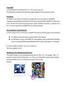
documentations: For detailed product information, carefully read the User's Manual. For instructions on how to use GIGABYTE's unique features, read or download the information on/from the Support&Downloads\Motherboard\Technology Guide page on our website. For product-related information, check - Gigabyte GA-EG41MF-US2H | Manual - Page 4
Items...6 GA-EG41MF-US2H Motherboard Layout 7 Block Diagram...8 Chapter 1 Hardware Installation 9 1-1 Installation Precautions 9 1-2 Product Specifications 10 1-3 Installing the CPU and CPU Cooler 13 1-3-1 Installing the CPU 13 1-3-2 Installing the CPU Cooler 15 1-4 Installing the Memory 16 - Gigabyte GA-EG41MF-US2H | Manual - Page 5
Chipset Drivers 61 3-2 Application Software 62 3-3 Technical Manuals 62 3-4 Contact ...63 3-5 System ...63 3-6 Download Center 64 Chapter 4 Unique Features 65 4-1 Xpress Recovery2 65 4-2 BIOS Update Utilities 68 4-2-1 Updating the BIOS with the Q-Flash Utility 68 4-2-2 Updating the BIOS with - Gigabyte GA-EG41MF-US2H | Manual - Page 6
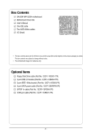
Box Contents GA-EG41MF-US2H motherboard Motherboard driver disk User's Manual One IDE cable Two SATA 3Gb/s cables I/O Shield • The box contents above are for reference only and the actual items shall depend on the product - Gigabyte GA-EG41MF-US2H | Manual - Page 7
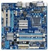
GA-EG41MF-US2H Motherboard Layout KB_MS PHASE LED IT8718 ATX_12V LGA775 FDD VGA LAN DVI HDMI Level Shifter OPTICAL Level Shifter USB_1394 BATTERY USB AUDIO F_AUDIO CPU_FAN PCIE_1 RTL8111C/D PCIE_16 PCI1 SPDIF_O PCI2 CODEC CD_IN SPDIF_I COMA GA-EG41MF-US2H Intel® G41 B_BIOS - Gigabyte GA-EG41MF-US2H | Manual - Page 8
CPU CLK+/(333/266/200 MHz) DDR2 800/667 MHz Dual Channel Memory GMCH CLK (333/266/200 MHz) 1 PCI Express x1 LAN RJ45 PCIe CLK (100 MHz) x1 RTL8111C/D x1 PCI Express Bus PCI Bus TSB43AB23 2 IEEE 1394a Intel® ICH7 CODEC Dual BIOS ATA-100/66/33 IDE Channel 4 SATA 3Gb/s 8 USB Ports - Gigabyte GA-EG41MF-US2H | Manual - Page 9
discharge (ESD) wrist strap when handling electronic components such as a motherboard, CPU or memory. If you do not have an ESD wrist strap, keep your hands are uncertain about any installation steps or have a problem related to the use of the product, please consult a certified computer technician - Gigabyte GA-EG41MF-US2H | Manual - Page 10
GIGABYTE's website for the latest CPU support list.) L2 cache varies with CPU 1333/1066/800 MHz FSB North Bridge: Intel® G41 Chipset South Bridge: Intel® ICH7 4 x 1.8V DDR2 DIMM sockets supporting up to 8 GB of system memory (Note 1) Dual channel memory GA-EG41MF-US2H Motherboard - 10 - - Gigabyte GA-EG41MF-US2H | Manual - Page 11
main power connector 1 x 4-pin ATX 12V power connector 1 x floppy disk drive connector 1 x IDE connector 4 x SATA 3Gb/s connectors 1 x CPU 1 x serial port header 1 x power LED header 1 x chassis intrusion header 1 x clearing CMOS jumper Back Panel 1 x PS/2 keyboard port - Gigabyte GA-EG41MF-US2H | Manual - Page 12
slot is in use, the HDMI and the DVI-D ports become unavailable. (Note 5) Whether the CPU/System fan speed control function is supported will depend on the CPU/ System cooler you install. (Note 6) Available functions in EasyTune may differ by motherboard model. GA-EG41MF-US2H Motherboard - 12 - - Gigabyte GA-EG41MF-US2H | Manual - Page 13
do so according to your hardware specifications including the CPU, graphics card, memory, hard drive, etc. 1-3-1 Installing the CPU A. Locate the alignment keys on the motherboard CPU socket and the notches on the CPU. LGA775 CPU Socket Alignment Key LGA 775 CPU Alignment Key Pin One Corner of - Gigabyte GA-EG41MF-US2H | Manual - Page 14
one corner of the CPU socket (or you may align the CPU notches with the socket alignment keys) and gently insert the CPU into position. Step 5: Once the CPU is properly inserted, replace the load plate and push the CPU socket lever back into its locked position. GA-EG41MF-US2H Motherboard - 14 - - Gigabyte GA-EG41MF-US2H | Manual - Page 15
. Check that the Male and Female push pins are joined closely. (Refer to your CPU cooler installation manual for instructions on installing the cooler.) Step 5: After the installation, check the back of the motherboard. If the push pin is inserted as the picture above, the installation is complete - Gigabyte GA-EG41MF-US2H | Manual - Page 16
installed, a message which says memory is operating in Flex Memory Mode will appear during the POST. Intel® Flex Memory Technology offers greater flexibility to upgrade by allowing different memory sizes to be populated and remain in Dual Channel mode/performance. GA-EG41MF-US2H Motherboard - 16 - - Gigabyte GA-EG41MF-US2H | Manual - Page 17
computer and unplug the power cord from the power outlet to prevent damage to the memory module. DDR2 DIMMs are not compatible to DDR DIMMs. Be sure to install DDR2 DIMMs on this motherboard. Notch DDR2 DIMM A DDR2 memory module has a notch, so it can only fit in one direction. Follow the steps - Gigabyte GA-EG41MF-US2H | Manual - Page 18
expansion card: • Make sure the motherboard supports the expansion card. Carefully read the manual that came with your expansion card. necessary, go to BIOS Setup to make any required BIOS changes for your expansion card(s). 7. Install the driver provided with the GA-EG41MF-US2H Motherboard - 18 - - Gigabyte GA-EG41MF-US2H | Manual - Page 19
Windows Vista, select Start>Control Panel>Sound, select Digital Output Device (HDMI) and then click Set Default. (Note 1) The DVI-D port does not support remove the cable from your device and then remove it from the motherboard. • When removing the cable, pull it straight out from the connector - Gigabyte GA-EG41MF-US2H | Manual - Page 20
LED LAN Port Connection/Speed LED: State Description Orange 1 Gbps data rate Green 100 Mbps data rate Off 10 Mbps data rate Activity LED: State Description Blinking Data transmission or receiving is occurring Off No data transmission or receiving is occurring GA-EG41MF-US2H Motherboard - Gigabyte GA-EG41MF-US2H | Manual - Page 21
to perform different functions via the audio software. Only microphones still MUST be connected to the default Mic in jack ( ). Refer to the instructions on setting up a 2/4/5.1/ 7.1-channel audio configuration in Chapter 5, "Configuring 2/4/5.1/7.1-Channel Audio." - 21 - Hardware Installation - Gigabyte GA-EG41MF-US2H | Manual - Page 22
14) SPDIF_O 15) F_USB1/F_USB2 16) F1_1394 17) COMA 18) CI 19) CLR_CMOS 20) PHASE LED Read the following guidelines before connecting external devices: • First make sure your devices are compliant with has been securely attached to the connector on the motherboard. GA-EG41MF-US2H Motherboard - 22 - - Gigabyte GA-EG41MF-US2H | Manual - Page 23
connector in the correct orientation. The 12V power connector mainly supplies power to the CPU. If the 12V power connector is not connected, the a 2x12 power supply, remove the protective cover from the main power connector on the motherboard. Do not insert the power supply cable into pins under - Gigabyte GA-EG41MF-US2H | Manual - Page 24
orientation (the black connector wire is the ground wire). The motherboard supports CPU fan speed control, which requires the use of a CPU fan with fan speed control design. For optimum heat dissipation, cable, please contact the local dealer. 34 33 2 1 GA-EG41MF-US2H Motherboard - 24 - - Gigabyte GA-EG41MF-US2H | Manual - Page 25
configuring master/slave settings for the IDE devices, read the instructions from the device manufacturers.) 40 39 2 1 7) SATA2_0 SATA 3Gb/s standard and are compatible with SATA 1.5Gb/s standard. Each SATA connector supports a single SATA device. SATA2_1 7 1 1 7 SATA2_0 SATA2_3 7 1 1 - Gigabyte GA-EG41MF-US2H | Manual - Page 26
BIOS configurations, date, and time information) in the CMOS when the computer is turned off. Replace the battery when the battery voltage drops to a low level, or the CMOS values may not be accurate or may be lost. You may clear the CMOS regulations. GA-EG41MF-US2H Motherboard - 26 - - Gigabyte GA-EG41MF-US2H | Manual - Page 27
beep will be heard if no problem is detected at system startup. If a problem is detected, the BIOS may issue beeps in different patterns to indicate the problem. Refer to Chapter 5, "Troubleshooting," for information about beep codes. • HD (Hard Drive Activity LED, Blue) Connects to the hard drive - Gigabyte GA-EG41MF-US2H | Manual - Page 28
GND 10 NC • The front panel audio header supports HD audio by default. If your chassis provides an AC'97 front panel audio module, refer to the instructions on how to activate AC'97 functionality via . Pin No. Definition 1 1 CD-L 2 GND 3 GND 4 CD-R GA-EG41MF-US2H Motherboard - 28 - - Gigabyte GA-EG41MF-US2H | Manual - Page 29
This header supports digital S/PDIF Out and connects a S/PDIF digital audio cable (provided by expansion cards) for digital audio output from your motherboard to certain PDIF digital audio cable, carefully read the manual for your expansion card. Pin No. Definition 1 1 SPDIFO 2 GND - - Gigabyte GA-EG41MF-US2H | Manual - Page 30
damage to the USB bracket. 16) F1_1394 (IEEE 1394a Header) The header conforms to IEEE 1394a specification. The IEEE 1394a header can provide one IEEE 1394a port via an optional IEEE 1394a bracket. IEEE 1394a device. Ensure that the cable is securely connected. GA-EG41MF-US2H Motherboard - 30 - - Gigabyte GA-EG41MF-US2H | Manual - Page 31
local dealer. 9 1 10 2 Pin No. 1 2 3 4 5 6 7 8 9 10 Definition NDCDNSIN NSOUT NDTRGND NDSRNRTSNCTSNRINo Pin 18) CI (Chassis Intrusion Header) This motherboard provides a chassis detection feature that detects if the chassis cover has been removed. This function requires a chassis with chassis - Gigabyte GA-EG41MF-US2H | Manual - Page 32
of lighted LEDs indicates the CPU loading. The higher the CPU loading, the more the number of lighted LEDs. To enable the Phase LED display function, please first enable Dynamic Energy Saver Advanced. Refer to Chapter 4, "Dynamic Energy Saver Advanced," for more details. GA-EG41MF-US2H Motherboard - Gigabyte GA-EG41MF-US2H | Manual - Page 33
Windows-based utility that searches and downloads the latest version of BIOS from the Internet and updates the BIOS. For instructions on using the Q-Flash and @BIOS utilities, refer to Chapter 4, "BIOS Update Utilities." • Because BIOS flashing is potentially risky, if you do not encounter problems - Gigabyte GA-EG41MF-US2H | Manual - Page 34
when the computer boots. Motherboard Model BIOS Version Award Modular BIOS v6.00PG, An Energy Star Ally Copyright (C) 1984-2009, Award Software, Inc. EG41MF-US2H F1a . . . . : BIOS Setup : XpressRecovery2 : Boot Menu : Qflash 03/09/2009-G41-ICH7-7A69PG0JC-00 Function Keys - Gigabyte GA-EG41MF-US2H | Manual - Page 35
to BIOS F12: Load CMOS from BIOS Change CPU's Clock & Voltage BIOS Setup Program Function Keys Move the selection bar to select an item Execute command or enter the submenu Main Menu: Exit the BIOS Setup program Submenus: Exit current submenu Increase the numeric - Gigabyte GA-EG41MF-US2H | Manual - Page 36
the CMOS and exit BIOS Setup. (Pressing can also carry out this task.) Exit Without Saving Abandon all changes and the previous settings remain in effect. Pressing to the confirmation message will exit BIOS Setup. (Pressing can also carry out this task.) GA-EG41MF-US2H Motherboard - Gigabyte GA-EG41MF-US2H | Manual - Page 37
overall system configurations. Incorrectly doing overclock/overvoltage may result in damage to CPU, chipset, or memory and reduce the useful life clear the CMOS values and reset the board to default values.) (Note) This item appears only if you install a CPU that supports this feature. - 37 - BIOS - Gigabyte GA-EG41MF-US2H | Manual - Page 38
(Mhz) Allows you to manually set the PCIe clock frequency. The adjustable range is from 90 MHz to 150 MHz. Auto sets the PCIe clock frequency to standard 100 MHz. (Default: Auto) (Note) This item appears only if you install a CPU that supports this feature. GA-EG41MF-US2H Motherboard - 38 - - Gigabyte GA-EG41MF-US2H | Manual - Page 39
CMOS Setup Utility-Copyright (C) 1984-2009 Award Software Advanced Clock Control CPU Clock Drive PCI Express Clock Drive CPU CPU Clock Drive Allows you to adjust the amplitude of the CPU 1000mV. CPU Clock Skew Allows you to set the CPU clock prior prior to the CPU clock. Options adjusting memory multiplier - Gigabyte GA-EG41MF-US2H | Manual - Page 40
memory multiplier. Options are dependent on CPU FSB and the (G)MCH Frequency Latch settings. Auto sets memory multiplier according to memory SPD data. (Default: Auto) Memory Frequency (Mhz) The first memory ESC: Exit F1: General Help F7: Optimized Defaults GA-EG41MF-US2H Motherboard - 40 - - Gigabyte GA-EG41MF-US2H | Manual - Page 41
(CMD) Options are: Auto (default), 1~3. ******** >>>>> Channel A/B Channel A/B Timing Settings CMOS Setup Utility-Copyright (C) 1984-2009 Award Software Channel A Timing Settings x Static tRead Value 0-Normal, 1-Advanced. ESC: Exit F1: General Help F7: Optimized Defaults - 41 - BIOS Setup - Gigabyte GA-EG41MF-US2H | Manual - Page 42
BIOS decide whether to enable this function. (Default) Disabled Disables this function. Enabled Enables this function to enhance memory compatibility. Channel A/B Driving Settings CMOS ), +8~-7. Cmd Driving Pull-Up Level Options are: Auto (default), +8~-7. GA-EG41MF-US2H Motherboard - 42 - - Gigabyte GA-EG41MF-US2H | Manual - Page 43
Auto (default), +8~-7. Clk Driving Pull-Down Level Options are: Auto (default), +8~-7. ******** Mother Board Voltage Control >>> CPU CPU Vcore The default is Auto. CPU Termination The default is Auto. CPU Reference The default is Auto. >>> MCH/ICH MCH Core The default is Auto. >>> DRAM DRAM Voltage - Gigabyte GA-EG41MF-US2H | Manual - Page 44
the detection of the device during the POST for faster system startup. Access Mode Sets the hard drive access mode. Options are: Auto (default), Large. GA-EG41MF-US2H Motherboard - 44 - - Gigabyte GA-EG41MF-US2H | Manual - Page 45
specifications. If you wish to enter the parameters manually ", 720K/3.5", 1.44M/3.5", 2.88M/3.5". Floppy 3 Mode Support Allows you to specify whether the installed floppy disk Memory These fields are read-only and are determined by the BIOS POST. Base Memory Also called conventional memory. - Gigabyte GA-EG41MF-US2H | Manual - Page 46
to issue warnings when a third party hardware monitor utility is installed. (Default: Enabled) (Note) This item is present only if you install a CPU that supports this feature. For more information about Intel CPUs' unique features, please visit Intel's website. GA-EG41MF-US2H Motherboard - 46 - - Gigabyte GA-EG41MF-US2H | Manual - Page 47
to HDD Allows the system to copy the BIOS image file to the hard drive. If the system BIOS is corrupted, it will be recovered from this image file. (Default: Enabled) (Note) This item is present only if you install a CPU that supports this feature. For more information about Intel CPUs' unique - Gigabyte GA-EG41MF-US2H | Manual - Page 48
HDCP contents. PAVP mode can support increased content protection and robustness memory during boot. This memory is not seen by the operating system and not available to any user application. Aero (DWM) in Windows Vista will always be turned off in this mode. GA-EG41MF-US2H Motherboard - Gigabyte GA-EG41MF-US2H | Manual - Page 49
+96)160MB, (128+96)224MB and (256+96)352MB. The table below shows the supported features of the P AVP Lite and Paranoid modes. Feature Compressed video buffer is encrypted Hardware 128-bit AES decryption Protected memory (96 MB reserved during boot) PAVP Lite Yes Yes No PAVP Paranoid Yes Yes Yes - Gigabyte GA-EG41MF-US2H | Manual - Page 50
CMOS Disabled Auto Disables the integrated SATA controller. Lets BIOS set SA TA devices to Combined or Enhanced onboard SATA controller is automatically configured to Combined mode, you can manually re-configure it to Enhanced mode as needed. Combined (Default) GA-EG41MF-US2H Motherboard - 50 - - Gigabyte GA-EG41MF-US2H | Manual - Page 51
Diagnostic Function) CMOS Setup Utility- Optimized Defaults This motherboard incorporates cable diagnostic cable is attached to the motherboard, the Status fields of Functioning Normally... If no cable problem is detected on the LAN cable Windows mode or when the LAN Boot ROM is activated. - 51 - Gigabyte GA-EG41MF-US2H | Manual - Page 52
When a Cable Problem Occurs... If a cable problem occurs on a specified pair of wires, the Status field will show Short and then length shown whether to detect USB storage devices, including USB flash drives and USB hard drives during the POST. (Default: Enabled) GA-EG41MF-US2H Motherboard - 52 - - Gigabyte GA-EG41MF-US2H | Manual - Page 53
resumed at any time. Enables the system to enter the ACPI S3 (Suspend to RAM) sleep state (default). In S3 sleep state, the system appears to be off signal from a modem that supports wake-up function. (Default: Enabled) (Note) Supported on Windows Vista operating system only. - 53 - BIOS Setup - Gigabyte GA-EG41MF-US2H | Manual - Page 54
system at a specific time on each day or on a specific day in a month the password to clear the password Memory The system returns to its last known awake state upon the return of the AC power. EuP Support Supported on Windows Vista operating system only. GA-EG41MF-US2H Motherboard - 54 - - Gigabyte GA-EG41MF-US2H | Manual - Page 55
2-9 PnP/PCI Configurations CMOS Setup Utility-Copyright (C) 1984-2009 Award Software PnP/PCI Configurations PCI1 Save F6: Fail-Safe Defaults ESC: Exit F1: General Help F7: Optimized Defaults BIOS auto-assigns IRQ to the first PCI slot. (Default) Assigns IRQ 3,4,5,7,9,10,11,12,14,15 to - Gigabyte GA-EG41MF-US2H | Manual - Page 56
disables the CPU fan speed control function. Enabled allows the CPU fan to run at different speed according to the CPU temperature. You can adjust the fan speed with EasyT une based on system requirements. If disabled, CPU fan runs at full speed. (Default: Enabled) GA-EG41MF-US2H Motherboard - 56 - Gigabyte GA-EG41MF-US2H | Manual - Page 57
CMOS from BIOS Load Optimized Defaults Press on this item and then press the key to load the optimal BIOS default settings. The BIOS defaults settings helps the system to operate in optimum state. Always load the Optimized defaults after updating the BIOS or after clearing the CMOS - Gigabyte GA-EG41MF-US2H | Manual - Page 58
you to view the BIOS settings but not to make changes. To clear the password, press on the password item and when requested for the password, press again. The message "PASSWORD DISABLED" will appear, indicating the password has been cancelled. GA-EG41MF-US2H Motherboard - 58 - - Gigabyte GA-EG41MF-US2H | Manual - Page 59
Item F10: Save & Exit Setup F11: Save CMOS to BIOS F12: Load CMOS from BIOS Save Data to CMOS Press on this item and press the key. This saves the changes to the CMOS and exits the BIOS Setup program. Press or to return to the BIOS Setup Main Menu. 2-15 Exit Without Saving - Gigabyte GA-EG41MF-US2H | Manual - Page 60
GA-EG41MF-US2H Motherboard - 60 - - Gigabyte GA-EG41MF-US2H | Manual - Page 61
other drivers. • After the drivers are installed, follow the onscreen instructions to restart your system. You can install other applications included in the motherboard driver disk. • For USB 2.0 driver support under the Windows XP operating system, please install the Windows XP Service Pack - Gigabyte GA-EG41MF-US2H | Manual - Page 62
that GIGABYTE develops and some free software. You can click the Install button on the right of an item to install it. 3-3 Technical Manuals This page provides GIGABYTE's application guides, content descriptions for this driver disk, and the motherboard manuals. GA-EG41MF-US2H Motherboard - 62 - Gigabyte GA-EG41MF-US2H | Manual - Page 63
3-4 Contact For the detailed contact information of the GIGABYTE T aiwan headquarter or worldwide branch of fices, click the URL on this page to link to the GIGABYTE w ebsite. 3-5 System This page provides the basic system information. - 63 - Drivers Installation - Gigabyte GA-EG41MF-US2H | Manual - Page 64
3-6 Download Center To update the BIOS, drivers, or applications, click the Download Center button to link to the GIGABYTE website. The latest version of the BIOS, drivers, or applications will be displayed. GA-EG41MF-US2H Motherboard - 64 - - Gigabyte GA-EG41MF-US2H | Manual - Page 65
system and drivers are installed. • memory • VESA compatible graphics card • Windows XP with SP1 or later, Windows supported. • Hard drives in RAID/AHCI mode are not supported. Installation and Configuration Turn on your system to boot from the Windows Vista setup disk. A. Installing Windows - Gigabyte GA-EG41MF-US2H | Manual - Page 66
Xpress Recovery2 cannot save the backup file. B. Accessing Xpress Recovery2 1. Boot from the motherboard driver disk to access Xpress Recovery2 for the first time. When you see the following message 2: When finished, go to Disk Management to check disk allocation. GA-EG41MF-US2H Motherboard - 66 - - Gigabyte GA-EG41MF-US2H | Manual - Page 67
D. Using the Restore Function in Xpress Recovery2 Select RESTORE to restore the backup to your hard drive in case the system breaks down. The RESTORE option will not be present if no backup is created before. E. Removing the Backup Step 1: If you wish to remove the backup file, select REMOVE. F. - Gigabyte GA-EG41MF-US2H | Manual - Page 68
, Inc. EG41MF-US2H F1a . . . . : BIOS Setup : XpressRecovery2 : Boot Menu : Qflash 03/09/2009-G41-ICH7-7A69PG0JC-00 Because BIOS flashing is potentially risky, please do it with caution. Inadequate BIOS flashing may result in system malfunction. GA-EG41MF-US2H Motherboard - 68 - Gigabyte GA-EG41MF-US2H | Manual - Page 69
arrow key to select Update BIOS from Drive and press . • The Save Main BIOS to Drive option allows you to save the current BIOS file. • Q-Flash only supports USB flash drive or hard drives using F AT32/16/12 file system. • If the BIOS update file is saved to a hard drive in RAID/AHCI mode or - Gigabyte GA-EG41MF-US2H | Manual - Page 70
Setup F11: Save CMOS to BIOS F12: Load CMOS from BIOS Load Optimized Defaults Press to load BIOS defaults Step 6: Select Save & Exit Setup and then press to save settings to CMOS and exit BIOS Setup. The procedure is complete after the system restarts. GA-EG41MF-US2H Motherboard - 70 - - Gigabyte GA-EG41MF-US2H | Manual - Page 71
. If the BIOS update file for your motherboard is not present on the @BIOS server site, please manually download the BIOS update file from GIGABYTE's website and follow the instructions in "Update the BIOS without Using the Internet Update Function" below. 2. Update the BIOS without Using the - Gigabyte GA-EG41MF-US2H | Manual - Page 72
hardware components such as CPU, chipset, and memory and reduce the useful life of these components. Before you do the overclock/overvoltage, make sure that you fully know each function of EasyTune 6, or system instability or other unexpected results may occur. GA-EG41MF-US2H Motherboard - 72 - - Gigabyte GA-EG41MF-US2H | Manual - Page 73
Mode, GIGABYTE Dynamic Energy Saver Advanced shows how much power they have saved in a set period of time. Meter Mode - Button Information Table Button Description 1 Dynamic Energy Saver On/Off Switch (Default: Off) 2 Motherboard Phase LED On/Off Switch (Default: On) 3 Dynamic CPU Frequency - Gigabyte GA-EG41MF-US2H | Manual - Page 74
Motherboard Phase LED On/Off Switch (Default: On) 3 Dynamic CPU Frequency Function On/Off Switch (Default: Off) 4 CPU Throttling Display 5 3-Level CPU Voltage Switch (Default:1) (Note 3) 6 CPU Voltage Display 7 Dynamic Power Phase Status 8 Current CPU . GA-EG41MF-US2H Motherboard - 74 - - Gigabyte GA-EG41MF-US2H | Manual - Page 75
for using Q-Share After installing Q-Share from the motherboard driver disk, go to Start>All Programs>GIGABYTE> Q-Share.exe to launch the Q-Share tool. shared data folder Changes the data folder to be shared (Note) Updates Q-Share online Displays the current Q-Share version Exits Q-Share (Note - Gigabyte GA-EG41MF-US2H | Manual - Page 76
the Microsoft Volume Shadow Copy Services technology, Time Repair allows you to quickly back up and restore your system data in the Windows Vista operating system. Time Repair supports NTFS file system and can so you cannot edit the contents of a shadow copy. GA-EG41MF-US2H Motherboard - 76 - - Gigabyte GA-EG41MF-US2H | Manual - Page 77
2/4/5.1/7.1-Channel Audio The motherboard provides six audio jacks on the back panel which support 2/4/5.1/7.1-channel audio. The Configuring Speakers: (The following instructions use Windows Vista as the example operating system.) Step 1: After installing the audio driver, the HD Audio Manager - Gigabyte GA-EG41MF-US2H | Manual - Page 78
open the Device advanced settings dialog box. Select the Mute the rear output device, when a front headphone plugged in check box. Click OK to complete. GA-EG41MF-US2H Motherboard - 78 - - Gigabyte GA-EG41MF-US2H | Manual - Page 79
S/PDIF In 1. Installing the S/PDIF In Cable: Step 1: First, attach the connector at the end of the cable to the SPDIF_I header on your motherboard. Step 2: Secure the metal bracket to the chassis back panel with a screw. 2. Configuring S/PDIF In: On the Digital Input screen, click the Default - Gigabyte GA-EG41MF-US2H | Manual - Page 80
S/PDIF Out: On the Digital Output screen, click the Default Format tab and then select the sample rate and bit depth. Click OK to complete. GA-EG41MF-US2H Motherboard - 80 - - Gigabyte GA-EG41MF-US2H | Manual - Page 81
5-1-3 Configuring Microphone Recording Step 1: After installing the audio driver, the HD Audio Manager icon will appear in the notification area. Doubleclick the icon to access the HD Audio Manager. Step 2: Connect your microphone to - Gigabyte GA-EG41MF-US2H | Manual - Page 82
and right-click on this icon. Select Recording Devices. Step 2: On the Recording tab, right-click on an empty space and select Show Disabled Devices. GA-EG41MF-US2H Motherboard - 82 - - Gigabyte GA-EG41MF-US2H | Manual - Page 83
. Be sure to save the recorded audio file upon completion. B. Playing the Recorded Sound: You can play your recording in a digital media player program that supports playback of WMA files. - 83 - Appendix - Gigabyte GA-EG41MF-US2H | Manual - Page 84
error 2 short: CMOS setting error 1 long, 9 short: BIOS ROM error 1 long, 1 short: Memory or motherboard error Continuous long beeps: Graphics card not inserted properly 1 long, 2 short: Monitor or graphics card error Continuous short beeps: Power error GA-EG41MF-US2H Motherboard - 84 - - Gigabyte GA-EG41MF-US2H | Manual - Page 85
the CPU cooler power cable to the motherboard. The problem is verified and solved. Check if the memory is installed properly on the memory slot. No Correctly insert the memory into the memory socket. Yes The problem is verified and solved. Insert the graphics card. Connect theATX main power - Gigabyte GA-EG41MF-US2H | Manual - Page 86
END If the procedure above is unable to solve your problem, contact the place of purchase or local dealer for help. Or go to the Support&Downloads\Technical Service Zone page to submit your question. Our customer service staff will reply you as soon as possible. GA-EG41MF-US2H Motherboard - 86 - - Gigabyte GA-EG41MF-US2H | Manual - Page 87
GIGABYTE. Our Commitment to Preserving the Environment In addition to high-efficiency performance, all GIGABYTE motherboards local government office, your household waste disposal service or where you purchased the product for user's manual and we will be glad to help you with your effort. - - Gigabyte GA-EG41MF-US2H | Manual - Page 88
disposed of properly. China Restriction of Hazardous Substances Table The following table is supplied in compliance with China's Restriction of Hazardous Substances (China RoHS) requirements: GA-EG41MF-US2H Motherboard - 88 - - Gigabyte GA-EG41MF-US2H | Manual - Page 89
- 89 - Appendix - Gigabyte GA-EG41MF-US2H | Manual - Page 90
GA-EG41MF-US2H Motherboard - 90 - - Gigabyte GA-EG41MF-US2H | Manual - Page 91
- 91 - Appendix - Gigabyte GA-EG41MF-US2H | Manual - Page 92
GA-EG41MF-US2H Motherboard - 92 - - Gigabyte GA-EG41MF-US2H | Manual - Page 93
- 93 - Appendix - Gigabyte GA-EG41MF-US2H | Manual - Page 94
GA-EG41MF-US2H Motherboard - 94 - - Gigabyte GA-EG41MF-US2H | Manual - Page 95
231, Taiwan TEL: +886-2-8912-4000 FAX: +886-2-8912-4003 Tech. and Non-Tech. Support (Sales/Marketing) : http://ggts.gigabyte.com.tw WEB address (English): http://www.gigabyte.com.tw WEB address (Chinese): http://www.gigabyte.tw G.B.T. INC. - U.S.A. TEL: +1-626-854-9338 FAX: +1-626-854-9339 Tech - Gigabyte GA-EG41MF-US2H | Manual - Page 96
language in the language list on the top right corner of the website. GIGABYTE Global Service System To submit a technical or non-technical (Sales/ Marketing) question, please link to : http://ggts.gigabyte.com.tw Then select your language to enter the system. GA-EG41MF-US2H Motherboard - 96 -
-
 1
1 -
 2
2 -
 3
3 -
 4
4 -
 5
5 -
 6
6 -
 7
7 -
8
-
9
-
10
-
11
-
12
-
13
-
14
-
15
-
16
-
17
-
18
-
19
-
20
-
21
-
22
-
23
-
24
-
25
-
26
-
27
-
28
-
29
-
30
-
31
-
32
-
33
-
34
-
35
-
36
-
37
-
38
-
39
-
40
-
41
-
42
-
43
-
44
-
45
-
46
-
47
-
48
-
49
-
50
-
51
-
52
-
53
-
54
-
55
-
56
-
57
-
58
-
59
-
60
-
61
-
62
-
63
-
64
-
65
-
66
-
67
-
68
-
69
-
70
-
71
-
72
-
73
-
74
-
75
-
76
-
77
-
78
-
79
-
80
-
81
-
82
-
83
-
84
-
85
-
86
-
87
-
88
-
89
-
90
-
91
-
92
-
93
-
94
-
95
-
96
 |
 |

GA-EG41MF-US2H
LGA775 socket motherboard for Intel
®
Core
TM
processor family/
Intel
®
Pentium
®
processor family/Intel
®
Celeron
®
processor family
User's Manual
Rev. 1101
12ME-EG41MFU2H-1101R