Gigabyte GA-EP31-DS3L Manual
Gigabyte GA-EP31-DS3L Manual
 |
View all Gigabyte GA-EP31-DS3L manuals
Add to My Manuals
Save this manual to your list of manuals |
Gigabyte GA-EP31-DS3L manual content summary:
- Gigabyte GA-EP31-DS3L | Manual - Page 1
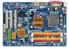
GA-EP31-DS3L LGA775 socket motherboard for Intel® CoreTM processor family/ Intel® Pentium® processor family/Intel® Celeron® processor family User's Manual Rev. 2102 12ME-EP31DS3L-2102R - Gigabyte GA-EP31-DS3L | Manual - Page 2
Motherboard GA-EP31-DS3L Aug. 4, 2008 Motherboard GA-EP31-DS3L Aug. 4, 2008 - Gigabyte GA-EP31-DS3L | Manual - Page 3
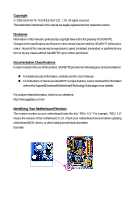
documentations: For detailed product information, carefully read the User's Manual. For instructions on how to use GIGABYTE's unique features, read or download the information on/from the Support&Downloads\Motherboard\Technology Guide page on our website. For product-related information, check - Gigabyte GA-EP31-DS3L | Manual - Page 4
...6 GA-EP31-DS3L Motherboard Layout 7 Block Diagram...8 Chapter 1 Hardware Installation 9 1-1 Installation Precautions 9 1-2 Product Specifications 10 1-3 Installing the CPU and CPU Cooler 13 1-3-1 Installing the CPU 13 1-3-2 Installing the CPU Cooler 15 1-4 Installing the Memory 16 - Gigabyte GA-EP31-DS3L | Manual - Page 5
Chipset Drivers 53 3-2 Application Software 54 3-3 Technical Manuals 54 3-4 Contact ...55 3-5 System ...55 3-6 Download Center 56 Chapter 4 Unique Features 57 4-1 Xpress Recovery2 57 4-2 BIOS Update Utilities 62 4-2-1 Updating the BIOS with the Q-Flash Utility 62 4-2-2 Updating the BIOS with - Gigabyte GA-EP31-DS3L | Manual - Page 6
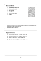
GA-EP31-DS3L motherboard Motherboard driver disk User's Manual One IDE cable Two SATA 3Gb/s cables I/O Shield • The box contents above are for reference only and the actual items shall depend on product package you obtain. The box contents are subject to change without notice. • The motherboard - Gigabyte GA-EP31-DS3L | Manual - Page 7
GA-EP31-DS3L Motherboard Layout KB_MS COAXIAL OPTICAL ATX_12V LGA775 CPU_FAN PWR_FAN PHASE LED COMA LPT GA-EP31-DS3L USB USB LAN AUDIO RTL8111C CODEC SPDIF_I CI IT8718 SPDIF_O CD_IN F_AUDIO Intel® P31/G31 DDR2_1 SYS_FAN1 PCIEX1_3 ATX PCIEX16 DDR2_2 DDR2_3 DDR2_4 PCIEX1_1 - Gigabyte GA-EP31-DS3L | Manual - Page 8
CPU CLK+/(333/266/200 MHz) 1 PCI Express x16 Host Interface DDR2 1066/800/667 MHz PCI Express Bus PCI Express x16 LAN RJ45 RTL 8111C x1 3 PCI Express x1 x 1 x 1 x 1 PCIe CLK (100 MHz) PCI Bus Intel® P31/G31 Intel® ICH7 CODEC Dual Channel Memory MCH CLK (333/266/200 MHz) Dual BIOS - Gigabyte GA-EP31-DS3L | Manual - Page 9
, carefully read the user's manual and follow these procedures: • Prior to installation, do not remove or break motherboard S/N (Serial Number) discharge (ESD) wrist strap when handling electronic components such as a motherboard, CPU or memory. If you do not have an ESD wrist strap, keep your hands - Gigabyte GA-EP31-DS3L | Manual - Page 10
GIGABYTE's website for the latest CPU support list.) Š L2 cache varies with CPU Š 1333/1066/800 MHz FSB Š North Bridge: Intel® P31/G31 Express Chipset Š South Bridge: Intel® ICH7 Š 4 x 1.8V DDR2 DIMM sockets supporting up to 4 GB of system memory (Note 1) Š Dual channel memory architecture Š Support - Gigabyte GA-EP31-DS3L | Manual - Page 11
Š System voltage detection Š CPU/System temperature detection Š CPU/System/Power fan speed detection Š CPU overheating warning Š CPU/System/Power fan fail warning Š CPU/System fan speed control(Note 2) BIOS Š 2 x 8 Mbit flash Š Use of licensed AWARD BIOS Š Support for DualBIOSTM Š PnP 1.0a - Gigabyte GA-EP31-DS3L | Manual - Page 12
in EasyTune may differ by motherboard model. (Note 4) Due to the hardware limitation, you must install the Intel® CoreTM 2 Extreme/ CoreTM 2 Quad/ CoreTM 2 Duo/ Pentium Dual-Core/ Celeron Dual-Core/ Celeron 400 Series CPU to enable support for Dynamic Energy Saver. GA-EP31-DS3L Motherboard - 12 - - Gigabyte GA-EP31-DS3L | Manual - Page 13
do so according to your hardware specifications including the CPU, graphics card, memory, hard drive, etc. 1-3-1 Installing the CPU A. Locate the alignment keys on the motherboard CPU socket and the notches on the CPU. LGA775 CPU Socket Alignment Key LGA 775 CPU Alignment Key Pin One Corner of - Gigabyte GA-EP31-DS3L | Manual - Page 14
one corner of the CPU socket (or you may align the CPU notches with the socket alignment keys) and gently insert the CPU into position. Step 5: Once the CPU is properly inserted, replace the load plate and push the CPU socket lever back into its locked position. GA-EP31-DS3L Motherboard - 14 - - Gigabyte GA-EP31-DS3L | Manual - Page 15
. Check that the Male and Female push pins are joined closely. (Refer to your CPU cooler installation manual for instructions on installing the cooler.) Step 5: After the installation, check the back of the motherboard. If the push pin is inserted as the picture above, the installation is complete - Gigabyte GA-EP31-DS3L | Manual - Page 16
first table for optimum performance. 3. Because of chipset limitations, do not populate both DIMM sockets of the same channel (e.g. DDR2_1 and DDR2_2) with double-sided memory modules to prevent system's failure to start or incorrect detection of memory modules. GA-EP31-DS3L Motherboard - 16 - - Gigabyte GA-EP31-DS3L | Manual - Page 17
computer and unplug the power cord from the power outlet to prevent damage to the memory module. DDR2 DIMMs are not compatible to DDR DIMMs. Be sure to install DDR2 DIMMs on this motherboard. Notch DDR2 DIMM A DDR2 memory module has a notch, so it can only fit in one direction. Follow the steps - Gigabyte GA-EP31-DS3L | Manual - Page 18
PCI Express x16 slot. Make sure the graphics card is locked by the latch at the end of the PCI Express x16 slot. • Removing the Card: Press the white latch at the end of the PCI Express x16 slot to release the card and then pull the card straight up from the slot. GA-EP31-DS3L Motherboard - 18 - - Gigabyte GA-EP31-DS3L | Manual - Page 19
supports the USB 2.0/1.1 specification. Use this port for USB devices such as an USB keyboard/mouse, USB printer, USB flash drive and etc. RJ-45 LAN Port The Gigabit Ethernet the cable from your device and then remove it from the motherboard. • When removing the cable, pull it straight out from - Gigabyte GA-EP31-DS3L | Manual - Page 20
to perform different functions via the audio software. Only microphones still MUST be connected to the default Mic in jack ( ). Refer to the instructions on setting up a 2/4/5.1/ 7.1-channel audio configuration in Chapter 5, "Configuring 2/4/5.1/7.1-Channel Audio." GA-EP31-DS3L Motherboard - 20 - - Gigabyte GA-EP31-DS3L | Manual - Page 21
14) SPDIF_I 15) SPDIF_O 16) F_USB1/F_USB2 17) CI 18) CLR_CMOS 19) BAT 20) PHASE LED Read the following guidelines before connecting external devices: • First make sure your devices are compliant with has been securely attached to the connector on the motherboard. - 21 - Hardware Installation - Gigabyte GA-EP31-DS3L | Manual - Page 22
cable to the power connector in the correct orientation. The 12V power connector mainly supplies power to the CPU. If the 12V power connector is not connected, the computer will not start. • To meet +5V +5V +5V (Only for 2x12-pinATX) GND (Only for 2x12-pin ATX) GA-EP31-DS3L Motherboard - 22 - - Gigabyte GA-EP31-DS3L | Manual - Page 23
fan cable, be sure to connect it in the correct orientation (the black connector wire is the ground wire). The motherboard supports CPU fan speed control, which requires the use of a CPU fan with fan speed control design. For optimum heat dissipation, it is recommended that a system fan be installed - Gigabyte GA-EP31-DS3L | Manual - Page 24
master/slave settings for the IDE devices, read the instructions from the device manufacturers.) 2 40 1 39 9) SATA2_0 supports a single SATA device. SATA2_0 SATA2_2 7 17 1 SATA2_1 SATA2_3 1 71 7 Pin No. 1 2 3 4 5 6 7 Definition GND TXP TXN GND RXN RXP GND GA-EP31-DS3L Motherboard - Gigabyte GA-EP31-DS3L | Manual - Page 25
• The front panel audio header supports HD audio by default. If your chassis provides an AC'97 front panel audio module, refer to the instructions on how to activate AC'97 functioninality via the audio software in Chapter 5, "Configuring 2/4/5.1/7.1-Channel Audio." • Audio signals will be present - Gigabyte GA-EP31-DS3L | Manual - Page 26
a beep code. One single short beep will be heard if no problem is detected at system startup. If a problem is detected, the BIOS may issue beeps in different patterns to indicate the problem. Refer to Chapter 5, "Troubleshooting," for information about beep codes. • HD (IDE Hard Drive Activity LED - Gigabyte GA-EP31-DS3L | Manual - Page 27
header. Pin No. Definition 1 1 CD-L 2 GND 3 GND 4 CD-R 14) SPDIF_I (S/PDIF In Header, Red) This header supports digital S/PDIF in and can connect to an audio device that supports digital audio out via an optional S/PDIF in cable. For purchasing the optional S/PDIF in cable, please contact - Gigabyte GA-EP31-DS3L | Manual - Page 28
(S/PDIF Out Header) This header supports digital S/PDIF out and connects a S/PDIF digital audio cable (provided by expansion cards) for digital audio output from your motherboard to certain expansion cards like graphics cards and sound cards. For example, some graphics cards may require you to use - Gigabyte GA-EP31-DS3L | Manual - Page 29
the jumper. Failure to do so may cause damage to the motherboard. • After system restart, go to BIOS Setup to load factory defaults (select Load Optimized Defaults) or manually configure the BIOS settings (refer to Chapter 2, "BIOS Setup," for BIOS configurations). - 29 - Hardware Installation - Gigabyte GA-EP31-DS3L | Manual - Page 30
The battery provides power to keep the values (such as BIOS configurations, date, and time information) in the CMOS when regulations. 20) PHASE LED The number of lighted LEDs indicates the CPU loading. The higher the CPU loading, the more the number of lighted LEDs. GA-EP31-DS3L Motherboard - 30 - Gigabyte GA-EP31-DS3L | Manual - Page 31
the GIGABYTE Q-Flash or @BIOS utility. • Q-Flash allows the user to quickly and easily upgrade or back up BIOS without entering the operating system. • @BIOS is a Windows-based utility that searches and downloads the latest version of BIOS from the Internet and updates the BIOS. For instructions on - Gigabyte GA-EP31-DS3L | Manual - Page 32
v6.00PG, An Energy Star Ally Copyright (C) 1984-2008, Award Software, Inc. Motherboard Model BIOS Version EP31-DS3L E5 . . . . : BIOS Setup : XpressRecovery2 : Boot Menu : Qflash 07/21/2008-P31-ICH7-6A99OG09C-00 Function Keys Function Keys: : POST Screen Press the - Gigabyte GA-EP31-DS3L | Manual - Page 33
1984-2008 Award Software ` Standard CMOS Features ` Advanced BIOS Features ` Integrated Peripherals ` Power Management Setup ` PnP/PCI Configurations ` PC Health Status ` MB Intelligent Tweaker(M.I.T.) Load Fail-Safe Defaults Load Optimized Defaults Set Supervisor Password Set User Password Save - Gigabyte GA-EP31-DS3L | Manual - Page 34
your CPU, memory, BIOS Setup. (Pressing can also carry out this task.) „ Exit Without Saving Abandon all changes and the previous settings remain in effect. Pressing to the confirmation message will exit BIOS Setup. (Pressing can also carry out this task.) GA-EP31-DS3L Motherboard - Gigabyte GA-EP31-DS3L | Manual - Page 35
Lets BIOS automatically detect IDE/SATA devices during the POST. (Default) If no IDE/SATA devices are used, set this item to None so the system will skip the detection of the device during the POST for faster system startup. Allows you to manually enter the specifications of the hard drive when - Gigabyte GA-EP31-DS3L | Manual - Page 36
and are determined by the BIOS POST. Base Memory Also called conventional memory. Typically, 640 KB will be reserved for the MS-DOS operating system. Extended Memory The amount of extended memory. Total Memory The total amount of memory installed on the system. GA-EP31-DS3L Motherboard - 36 - - Gigabyte GA-EP31-DS3L | Manual - Page 37
-Copyright (C) 1984-2008 Award Software Advanced BIOS Features ` Hard Disk Boot Priority First Boot Device Second Boot Device Third Boot Device Password Check HDD S.M.A.R.T. Capability Limit CPUID Max. to 3 (Note) No-Execute Memory Protect (Note) Load-Line Calibration CPU Enhanced Halt (C1E) (Note - Gigabyte GA-EP31-DS3L | Manual - Page 38
card as the first display. (Default) PEG Sets the PCI Express graphics card as the first display. (Note) This item is present only if you install a CPU that supports this feature. For more information about Intel CPUs' unique features, please visit Intel's website. GA-EP31-DS3L Motherboard - Gigabyte GA-EP31-DS3L | Manual - Page 39
Software Integrated Peripherals On-Chip Primary PCI IDE On-Chip SATA Mode x PATA IDE Set to SATA Port 0/2 Set to SATA Port 1/3 Set to USB Controller USB 2.0 Controller USB Keyboard Support USB Mouse Support Auto Lets BIOS set SATA to Combined mode, you can manually re-configure it to Enhanced - Gigabyte GA-EP31-DS3L | Manual - Page 40
: Enabled) USB Keyboard Support Allows USB keyboard to be used in MS-DOS. (Default: Disabled) USB Mouse Support Allows USB mouse to be motherboard, the Status fields of all four pairs of wires will show Open and the Length fields show 0m, as shown in the figure above. GA-EP31-DS3L Motherboard - Gigabyte GA-EP31-DS3L | Manual - Page 41
will operate at a normal speed of 10/100/1000Mbps in Windows mode or when the LAN Boot ROM is activated. When a Cable Problem Occurs... If a cable problem occurs on a specified pair of wires, the Status field (Enhanced Parallel Port), ECP (Extended Capabilities Port), ECP+EPP. - 41 - BIOS Setup - Gigabyte GA-EP31-DS3L | Manual - Page 42
time. S3(STR) Enables the system to enter the ACPI S3 (Suspend to RAM) sleep state (default). In S3 sleep state, the system appears to be off a modem that supports wake-up function. (Default: Enabled) (Note) Supported on Windows® Vista® operating system only. GA-EP31-DS3L Motherboard - 42 - - Gigabyte GA-EP31-DS3L | Manual - Page 43
Date (of Month) Alarm : Turn on the system at a specific time on each day or on a specific day in a month. Time (hh: mm: ss) Alarm : Memory The system returns to its last known awake state upon the return of the AC power. (Note) Supported on Windows® Vista® operating system only. - 43 - BIOS - Gigabyte GA-EP31-DS3L | Manual - Page 44
1984-2008 Award Software PnP/PCI BIOS auto-assigns IRQ to the second PCI slot. (Default) Assigns IRQ 3,4,5,7,9,10,11,12,14,15 to the second PCI slot. BIOS auto-assigns IRQ to the third PCI slot. (Default) Assigns IRQ 3,4,5,7,9,10,11,12,14,15 to the third PCI slot. GA-EP31-DS3L Motherboard - Gigabyte GA-EP31-DS3L | Manual - Page 45
to the motherboard CI header. CPU Temperature Displays current system/CPU temperature. Current CPU/SYSTEM/POWER FAN Speed (RPM) Displays current CPU/system/power fan speed. CPU Warning Temperature Sets the warning threshold for CPU temperature. When CPU temperature exceeds the threshold, BIOS - Gigabyte GA-EP31-DS3L | Manual - Page 46
or disables the CPU fan speed control function. Enabled allows the CPU fan to run at different speed according to the CPU temperature. You can adjust the fan speed with EasyTune based on system requirements. If disabled, CPU fan runs at full speed. (Default: Enabled) GA-EP31-DS3L Motherboard - 46 - Gigabyte GA-EP31-DS3L | Manual - Page 47
overclock/overvoltage may result in damage to CPU, chipset, or memory and reduce the useful life of these components. This page is for advanced users Robust Graphics Booster Robust Graphics Booster (R.G.B.) helps to enhance the performance of the graphics chip and memory. Auto allows the BIOS to - Gigabyte GA-EP31-DS3L | Manual - Page 48
MHz FSB CPU, set this item to 333 MHz. Important It is highly recommended that the CPU frequency be set in accordance with the CPU specifications. PCI Express Frequency (Mhz) Allows you to manually set the Lets the system operate at its best performance level. GA-EP31-DS3L Motherboard - 48 - - Gigabyte GA-EP31-DS3L | Manual - Page 49
that is automatically adjusted according to the CPU Host Frequency (Mhz) and System Memory Multiplier settings. ******** System Voltage Optimized ******** System Voltage Control Determines whether to manually set the system voltages. Auto lets BIOS automatically set the system voltages as required - Gigabyte GA-EP31-DS3L | Manual - Page 50
Press on this item and then press the key to load the optimal BIOS default settings. The BIOS defaults settings helps the system to operate in optimum state. Always load the Optimized defaults after updating the BIOS or after clearing the CMOS values. GA-EP31-DS3L Motherboard - 50 - - Gigabyte GA-EP31-DS3L | Manual - Page 51
2-12 Set Supervisor/User Password CMOS Setup Utility-Copyright (C) 1984-2008 Award Software ` Standard CMOS Features ` Advanced BIOS Features ` Integrated Peripherals ` Power Management Setup ` PnP/PCI ConfiguratioEnns ter Password: ` PC Health Status ` MB Intelligent Tweaker(M.I.T.) Load Fail- - Gigabyte GA-EP31-DS3L | Manual - Page 52
Setup F11: Save CMOS to BIOS F12: Load CMOS from BIOS Abandon all Data Press on this item and press the key. This exits the BIOS Setup without saving the changes made in BIOS Setup to the CMOS. Press or to return to the BIOS Setup Main Menu. GA-EP31-DS3L Motherboard - 52 - - Gigabyte GA-EP31-DS3L | Manual - Page 53
other drivers. • After the drivers are installed, follow the onscreen instructions to restart your system. You can install other applications included in the motherboard driver disk. • For USB 2.0 driver support under the Windows XP operating system, please install the Windows XP Service Pack - Gigabyte GA-EP31-DS3L | Manual - Page 54
that GIGABYTE develops and some free software. You can click the Install button on the right of an item to install it. 3-3 Technical Manuals This page provides GIGABYTE's application guides, content descriptions for this driver disk, and the motherboard manuals. GA-EP31-DS3L Motherboard - 54 - Gigabyte GA-EP31-DS3L | Manual - Page 55
3-4 Contact Click the URL on this page to link to the GIGABYTE Web site. Or read the last page of this manual to check the contact information for GIGABYTE Taiwan headquarter or worldwide branch offices. 3-5 System This page provides the basic system information. - 55 - Drivers Installation - Gigabyte GA-EP31-DS3L | Manual - Page 56
3-6 Download Center To update the BIOS, drivers, or applications, click the Download Center button to link to the GIGABYTE Web site. The latest version of the BIOS, drivers, or applications will be displayed. GA-EP31-DS3L Motherboard - 56 - - Gigabyte GA-EP31-DS3L | Manual - Page 57
memory • VESA compatible graphics card • Windows® XP with SP1 or later • Xpress Recovery and Xpress Recovery2 are different utilities. For example, a backup file created with Xpress Recovery cannot be restored using Xpress Recovery2. • USB hard drives are not supported. • Hard drives in RAID/AHCI - Gigabyte GA-EP31-DS3L | Manual - Page 58
Windows XP as the example operating system.) A. Installing Windows XP and Partitioning the Hard Drive 1. Set CD-ROM drive as the first boot device under "Advanced BIOS Features" in the BIOS ) and begin the installation of the operating system (Figure 3). Figure 3 GA-EP31-DS3L Motherboard - 58 - - Gigabyte GA-EP31-DS3L | Manual - Page 59
4. After the operating system is installed, right-click the My Computer icon on your desktop and select Manage (Figure 4). Go to Computer Management to check disk allocation. Xpress Recovery2 will save the backup file to the unallocated space (black stripe along the top)(Figure 5). Please note that - Gigabyte GA-EP31-DS3L | Manual - Page 60
drive contains the Windows operating system. When the Windows operating system is detected, Xpress Recovery2 will begin the backup process (Figure 11). Figure 10 Figure 11 3. When finished, go to Disk Management to check disk allocation. Figure 12 GA-EP31-DS3L Motherboard Xpress Recovery2 will - Gigabyte GA-EP31-DS3L | Manual - Page 61
D. Using the Restore Function in Xpress Recovery2 Select RESTORE to restore the backup to your hard drive in case the system breaks down. The RESTORE option will not be present if no backup is created before (Figure 13, 14). Figure 13 Figure 14 E. Removing the Backup 1. If you wish to remove the - Gigabyte GA-EP31-DS3L | Manual - Page 62
Software, Inc. EP31-DS3L E5 . . . . : BIOS Setup : XpressRecovery2 : Boot Menu : Qflash 07/21/2008-P31-ICH7-6A99OG09C-00 Because BIOS flashing is potentially risky, please do it with caution. Inadequate BIOS flashing may result in system malfunction. GA-EP31-DS3L Motherboard - Gigabyte GA-EP31-DS3L | Manual - Page 63
16/12 file system. • If the BIOS update file is saved to a hard drive in RAID/AHCI mode or a hard drive attached to an independent IDE/SATA controller, use the key during the POST to access Q-Flash. 2. Select Floppy A and press . Q-Flash Utility v2.05 Flash Type/Size MXIC 25L8005 1M - Gigabyte GA-EP31-DS3L | Manual - Page 64
F11: Save CMOS to BIOS F12: Load CMOS from BIOS Time, Date, Hard Disk Type... Press to load BIOS defaults Step 6: Select Save & Exit Setup and then press to save settings to CMOS and exit BIOS Setup. The procedure is complete after the system restarts. GA-EP31-DS3L Motherboard - 64 - - Gigabyte GA-EP31-DS3L | Manual - Page 65
location and then download the BIOS file that matches your motherboard model. Follow the on- screen instructions to complete. If the BIOS update file for your motherboard is not present on the @BIOS server site, please manually download the BIOS update file from GIGABYTE's website and follow - Gigabyte GA-EP31-DS3L | Manual - Page 66
Pro, or system instability or other unexpected results may occur. (Note 1) Available functions in EasyTune 5 Pro may differ by motherboard model. (Note 2) C.I.A. and M.I.B. may provide optimizations for CPU and memory, enhancing the performance of these components. GA-EP31-DS3L Motherboard - 66 - - Gigabyte GA-EP31-DS3L | Manual - Page 67
Mode, GIGABYTE Dynamic Energy Saver Advanced shows how much power they have saved in a set period of time. Meter Mode - Button Information Table Button Description 1 Dynamic Energy Saver On/Off Switch (Default: Off) 2 Motherboard Phase LED On/Off Switch (Default: On) 3 Dynamic CPU Frequency - Gigabyte GA-EP31-DS3L | Manual - Page 68
Celeron 400 Series CPU to enable support for Dynamic Energy Saver. (Note 2) Before using the DES function, make sure the CPU Enhanced Halt (C1E) and CPU EIST Function items in the BIOS Setup program are reset when the total power saving reaches 99999999 Watts. GA-EP31-DS3L Motherboard - 68 - - Gigabyte GA-EP31-DS3L | Manual - Page 69
example, users can listen to MP3 music, have an Internet chat, make a telephone call over the Internet, and etc. all at the same time. A. Configuring Speakers: (The following instructions use Windows XP as the example operating system.) Step 1: After installing the audio driver, the Audio Manager - Gigabyte GA-EP31-DS3L | Manual - Page 70
detection check box. Click OK to complete. D. Muting the Back Panel Audio (For HD Audio Only): Click the tool icon on the Audio I/O tab. On the Connector Settings box, select the Mute rear panel output when front headphone plugged in check box. Click OK to complete. GA-EP31-DS3L Motherboard - 70 - - Gigabyte GA-EP31-DS3L | Manual - Page 71
PDIF In: The S/PDIF in jacks allow you to input digital audio signals to the computer for audio processing. A. Installing the S/PDIF In Cable: Step 1: First, attach the connector at the end of the cable to the SPDIF_I header on your motherboard. Step 2: Secure the metal bracket to the chassis back - Gigabyte GA-EP31-DS3L | Manual - Page 72
cable or a S/PDIF optical cable (either one) to an external decoder for transmitting the S/PDIF digital audio signals. S/PDIF Coaxial Cable S/PDIF Optical Cable C. Configuring S/PDIF out: Click the tool icon in SPDIF In and SPDIF Out connectors may differ by model. GA-EP31-DS3L Motherboard - 72 - - Gigabyte GA-EP31-DS3L | Manual - Page 73
5-1-3 Configuring Microphone Recording Step 1: After installing the audio driver, the Audio Manager icon will appear in your system tray. Double-click the icon to access the Audio Control Panel. Step 2: Connect your microphone to the Mic in jack (pink) on the back panel or the Mic in jack (pink) on - Gigabyte GA-EP31-DS3L | Manual - Page 74
recording you just made. (Note) Based on the audio specifications, to adjust the recording sound, use the Recording option to set the recording sound for your recording device(s) altogether. Select Realtek HD Audio Input in the Mixer device list Recording Control GA-EP31-DS3L Motherboard - 74 - - Gigabyte GA-EP31-DS3L | Manual - Page 75
, and then click Sound Recorder to begin the sound recording. 5-1-4 Using the Sound Recorder Recording the Sound: 1. Make sure you have connected the audio input device (e.g. microphone) to the computer. 2. On the File menu, choose New. 3. To record a sound file, click the Recording but- ton . 4. To - Gigabyte GA-EP31-DS3L | Manual - Page 76
mean? A: The following Award BIOS beep code descriptions may help you identify possible computer problems. (For reference only.) 1 short: System boots successfully 2 short: CMOS setting error 1 long, 1 short: Memory or motherboard error 1 long, 2 short: Monitor or graphics card error 1 long, 3 short - Gigabyte GA-EP31-DS3L | Manual - Page 77
. Secure the CPU No cooler on the CPU. Connect the CPU cooler power cable to the motherboard. The problem is verified and solved. Check if the memory is installed properly on the memory slot. No Correctly insert the memory into the memory socket. Yes Insert the graphics card. Connect the - Gigabyte GA-EP31-DS3L | Manual - Page 78
. END If the procedure above is unable to solve your problem, contact the place of purchase or local dealer for help. Or go to the Support&Downloads\Technical Service Zone page to submit your question. Our customer service staff will reply you as soon as possible. GA-EP31-DS3L Motherboard - 78 - - Gigabyte GA-EP31-DS3L | Manual - Page 79
GIGABYTE. Our Commitment to Preserving the Environment In addition to high-efficiency performance, all GIGABYTE motherboards government office, your household waste disposal service or where you purchased the product for product's user's manual and we will be glad to help you with your effort. - Gigabyte GA-EP31-DS3L | Manual - Page 80
disposed of properly. China Restriction of Hazardous Substances Table The following table is supplied in compliance with China's Restriction of Hazardous Substances (China RoHS) requirements: GA-EP31-DS3L Motherboard - 80 - - Gigabyte GA-EP31-DS3L | Manual - Page 81
- 81 - Appendix - Gigabyte GA-EP31-DS3L | Manual - Page 82
GA-EP31-DS3L Motherboard - 82 - - Gigabyte GA-EP31-DS3L | Manual - Page 83
231, Taiwan TEL: +886-2-8912-4000 FAX: +886-2-8912-4003 Tech. and Non-Tech. Support (Sales/Marketing) : http://ggts.gigabyte.com.tw WEB address (English): http://www.gigabyte.com.tw WEB address (Chinese): http://www.gigabyte.tw G.B.T. INC. - U.S.A. TEL: +1-626-854-9338 FAX: +1-626-854-9339 Tech - Gigabyte GA-EP31-DS3L | Manual - Page 84
language in the language list on the top right corner of the website. GIGABYTE Global Service System To submit a technical or non-technical (Sales/ Marketing) question, please link to : http://ggts.gigabyte.com.tw Then select your language to enter the system. GA-EP31-DS3L Motherboard - 84 -
-
 1
1 -
 2
2 -
 3
3 -
 4
4 -
 5
5 -
 6
6 -
 7
7 -
8
-
9
-
10
-
11
-
12
-
13
-
14
-
15
-
16
-
17
-
18
-
19
-
20
-
21
-
22
-
23
-
24
-
25
-
26
-
27
-
28
-
29
-
30
-
31
-
32
-
33
-
34
-
35
-
36
-
37
-
38
-
39
-
40
-
41
-
42
-
43
-
44
-
45
-
46
-
47
-
48
-
49
-
50
-
51
-
52
-
53
-
54
-
55
-
56
-
57
-
58
-
59
-
60
-
61
-
62
-
63
-
64
-
65
-
66
-
67
-
68
-
69
-
70
-
71
-
72
-
73
-
74
-
75
-
76
-
77
-
78
-
79
-
80
-
81
-
82
-
83
-
84
 |
 |

GA-EP31-DS3L
LGA775 socket motherboard for Intel
®
Core
TM
processor family/
Intel
®
Pentium
®
processor family/Intel
®
Celeron
®
processor family
User's Manual
Rev. 2102
12ME-EP31DS3L-2102R