Gigabyte GA-EP35-DS3P Manual
Gigabyte GA-EP35-DS3P Manual
 |
UPC - 818313005014
View all Gigabyte GA-EP35-DS3P manuals
Add to My Manuals
Save this manual to your list of manuals |
Gigabyte GA-EP35-DS3P manual content summary:
- Gigabyte GA-EP35-DS3P | Manual - Page 1
GA-EP35-DS3P LGA775 socket motherboard for Intel® CoreTM processor family/ Intel® Pentium® processor family/Intel® Celeron® processor family User's Manual Rev. 2101 12ME-EP35DS3P-2101R - Gigabyte GA-EP35-DS3P | Manual - Page 2
Motherboard GA-EP35-DS3P Dec. 14, 2007 Motherboard GA-EP35-DS3P Dec. 14, 2007 - Gigabyte GA-EP35-DS3P | Manual - Page 3
with the product. „ For detailed product information, carefully read the User's Manual. „ For instructions on how to use GIGABYTE's unique features, read or download the information on/from the Support\Motherboard\Technology Guide page on our website. For product-related information, check on our - Gigabyte GA-EP35-DS3P | Manual - Page 4
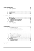
...6 GA-EP35-DS3P Motherboard Layout 7 Block Diagram...8 Chapter 1 Hardware Installation 9 1-1 Installation Precautions 9 1-2 Product Specifications 10 1-3 Installing the CPU and CPU Cooler 13 1-3-1 Installing the CPU 13 1-3-2 Installing the CPU Cooler 15 1-4 Installing the Memory 16 - Gigabyte GA-EP35-DS3P | Manual - Page 5
68 4-2-2 Updating the BIOS with the @BIOS Utility 71 4-3 EasyTune 5 Pro 73 4-4 Dynamic Energy Saver 74 4-5 Windows Vista ReadyBoost 76 Chapter 5 Appendix ...77 5-1 Configuring SATA Hard Drive(s 77 5-1-1 Configuring Intel® ICH9R SATA Controllers 77 5-1-2 Configuring GIGABYTE SATA2 SATA - Gigabyte GA-EP35-DS3P | Manual - Page 6
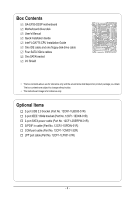
Box Contents GA-EP35-DS3P motherboard Motherboard driver disk User's Manual Quick Installation Guide Intel® LGA775 CPU Installation Guide One IDE cable and one floppy disk drive cable Four SATA 3Gb/s cables One SATA bracket I/O Shield • The box contents above are for reference only - Gigabyte GA-EP35-DS3P | Manual - Page 7
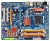
GA-EP35-DS3P Motherboard Layout RCA SPDIF-1 KB_MS SYS_FAN1 USB ATX_12V_2X LGA775 PHASE LED PWR_FAN PCIE_12V ATX 1394_2 1394_1 USB USB GA-EP35-DS3P LAN USB CPU_FAN F_AUDIO AUDIO PCIE_1 Intel® P35 RTL8111B PCIE_16_1 NB_FAN FDD DDRII1 DDRII2 DDRII3 DDRII4 CODEC PCIE_2 PCIE_3 - Gigabyte GA-EP35-DS3P | Manual - Page 8
IDE Channel GIGABYTE SATA2 PCI Bus TSB43AB23 3 IEEE 1394a LGA775 Processor CPU CLK+/(400 (O.C.)/333/266/200 MHz) Host Interface DDR2 1200 (O.C.)/1066/ 800/667 MHz Intel® P35 Dual Channel Memory MCH CLK (400 (O.C.)/333/266/200 MHz) Intel® ICH9R CODEC Dual BIOS 6 SATA 3Gb/s 12 USB Ports - Gigabyte GA-EP35-DS3P | Manual - Page 9
, CPU or memory. If you do not have an ESD wrist strap, keep your hands dry and first touch a metal object to eliminate static electricity. • Prior to installing the motherboard, please have it on top of an antistatic pad or within an electrostatic shielding container. • Before unplugging the power - Gigabyte GA-EP35-DS3P | Manual - Page 10
in the LGA 775 package (Go to GIGABYTE's website for the latest CPU support list.) Š L2 cache varies with CPU Š 1600 (O.C.)/1333/1066/800 MHz FSB Š North Bridge: Intel® P35 Chipset Š South Bridge: Intel® ICH9R Š 4 x 1.8V DDR2 DIMM sockets supporting up to 8 GB of system memory (Note 1) Š Dual - Gigabyte GA-EP35-DS3P | Manual - Page 11
connected to the internal USB headers) Internal Connectors Š 1 x 24-pin ATX main power connector Š 1 x 8-pin ATX 12V power connector Š 1 x 4-pin PCIe 12V power connector Š 1 x floppy disk drive connector Š 1 x IDE connector Š 8 x SATA 3Gb/s connectors Š 1 x CPU fan header Š 2 x system fan - Gigabyte GA-EP35-DS3P | Manual - Page 12
the CPU fan speed control function is supported will depend on the CPU cooler you install. (Note 4) Available functions in Easytune may differ by motherboard model. (Note 5) Due to chipset limitation, Intel ICH9R RAID driver does not support Windows 2000 operating system. GA-EP35-DS3P Motherboard - Gigabyte GA-EP35-DS3P | Manual - Page 13
so according to your hardware specifications including the CPU, graphics card, memory, hard drive, etc. 1-3-1 Installing the CPU A. Locate the alignment keys on the motherboard CPU socket and the notches on the CPU. LGA775 CPU Socket Alignment Key LGA 775 CPU Alignment Key Pin One Corner of the - Gigabyte GA-EP35-DS3P | Manual - Page 14
one corner of the CPU socket (or you may align the CPU notches with the socket alignment keys) and gently insert the CPU into position. Step 5: Once the CPU is properly inserted, replace the load plate and push the CPU socket lever back into its locked position. GA-EP35-DS3P Motherboard - 14 - - Gigabyte GA-EP35-DS3P | Manual - Page 15
installation manual for instructions on installing the cooler.) Step 5: After the installation, check the back of the motherboard. If the push pin is inserted as the picture above, the installation is complete. Step 6: Finally, attach the power connector of the CPU cooler to the CPU fan header - Gigabyte GA-EP35-DS3P | Manual - Page 16
installed, a message which says memory is operating in Flex Memory Mode will appear during the POST. Intel® Flex Memory Technology offers greater flexibility to upgrade by allowing different memory sizes to be populated and remain in Dual Channel mode/performance. GA-EP35-DS3P Motherboard - 16 - - Gigabyte GA-EP35-DS3P | Manual - Page 17
, make sure to turn off the computer and unplug the power cord from the power outlet to prevent damage to the memory module. DDR2 DIMMs are not compatible to DDR DIMMs. Be sure to install DDR2 DIMMs on this motherboard. Notch DDR2 DIMM A DDR2 memory module has a notch, so it can only fit in one - Gigabyte GA-EP35-DS3P | Manual - Page 18
pull the card straight up from the slot. • The motherboard provides a PCIE_12V power connector, which can supply extra power to the onboard PCI Express x16 slots. When you install two graphics cards, connect the power cable from your power supply to this connector. GA-EP35-DS3P Motherboard - 18 - - Gigabyte GA-EP35-DS3P | Manual - Page 19
to install the SATA bracket: Step 1: Locate one free PCI slot and secure the SATA bracket to the chassis back panel with a screw. Step 2: Connect the SATA cable from the bracket to the SATA port on your motherboard. Step 3: Step 4: Connect the power Plug one end of the cable from the bracket - Gigabyte GA-EP35-DS3P | Manual - Page 20
USB Port The USB port supports the USB 2.0/1.1 specification. Use this port for USB devices such as an USB keyboard/mouse, USB printer, USB states of the LAN port LEDs. Connection/ Speed LED Activity LED LAN Port Connection/Speed LED: State Description Orange 1 GA-EP35-DS3P Motherboard - 20 - - Gigabyte GA-EP35-DS3P | Manual - Page 21
to perform different functions via the audio software. Only microphones still MUST be connected to the default Mic in jack ( ). Refer to the instructions on setting up a 2/4/5.1/ 7.1-channel audio configuration in Chapter 5, "Configuring 2/4/5.1/7.1-Channel Audio." - 21 - Hardware Installation - Gigabyte GA-EP35-DS3P | Manual - Page 22
ATX 3) PCIE_12V 4) PHASE LED 5) CPU_FAN 6) SYS_FAN1 power cord from the power outlet to prevent damage to the devices. • After installing the device and before turning on the computer, make sure the device cable has been securely attached to the connector on the motherboard. GA-EP35-DS3P Motherboard - Gigabyte GA-EP35-DS3P | Manual - Page 23
orientation. The 12V power connector mainly supplies power to the CPU. If the 12V power connector is not connected, the computer will not start. • Use of a power supply providing a 2x4 12V power connector is recommended by the CPU manufacturer when using an Intel Extreme Edition CPU (130W). • To - Gigabyte GA-EP35-DS3P | Manual - Page 24
power to the PCI Express x16 slots on the motherboard. Connect the power supply cable to this connector when using two graphics cards. Failure to do so may lead to an unstable system. 1 PIin No. Definition 1 NC 2 GND 3 GND 4 +12V 4) PHASE LED The number of lighted LEDs indicates the CPU - Gigabyte GA-EP35-DS3P | Manual - Page 25
in the correct orientation. Most fans are designed with color-coded power connector wires. A red power connector wire indicates a positive connection and requires a +12V voltage. The black connector wire is the ground wire. The motherboard supports CPU fan speed control, which requires the use of - Gigabyte GA-EP35-DS3P | Manual - Page 26
stripe of different color. 34 33 2 1 10) IDE (IDE Connector) The IDE connector supports up to two IDE devices such as hard drives and optical drives. Before attaching the IDE the IDE devices, read the instructions from the device manufacturers.) 1 2 GA-EP35-DS3P Motherboard 39 40 - 26 - - Gigabyte GA-EP35-DS3P | Manual - Page 27
and are compatible with SATA 1.5Gb/s standard. Each SATA connector supports a single SATA device. The GIGABYTE SATA2 controller supports RAID 0 and RAID 1. Refer to Chapter 5, "Configuring SATA Hard Drive(s)," for instructions on configuring a RAID array. Pin No. Definition 1 GND 2 TXP - Gigabyte GA-EP35-DS3P | Manual - Page 28
powered off (S5). Pin No. Definition 1 MPD+ 2 MPD- 1 3 MPD- System Status LED S0 On S1 Blinking S3/S4/S5 Off 14) BAT (Battery) The battery provides power to keep the values (such as BIOS be handled in accordance with local environmental regulations. GA-EP35-DS3P Motherboard - 28 - - Gigabyte GA-EP35-DS3P | Manual - Page 29
a beep code. One single short beep will be heard if no problem is detected at system startup. If a problem is detected, the BIOS may issue beeps in different patterns to indicate the problem. Refer to Chapter 5, "Troubleshooting," for information about beep codes. • HD (Hard Drive Activity LED, Blue - Gigabyte GA-EP35-DS3P | Manual - Page 30
10 NC • The front panel audio header supports HD audio by default. If your chassis provides an AC'97 front panel audio module, refer to the instructions on how to activate AC'97 functioninality via header. 1 Pin No. Definition 1 CD-L 2 GND 3 GND 4 CD-R GA-EP35-DS3P Motherboard - 30 - - Gigabyte GA-EP35-DS3P | Manual - Page 31
supports digital S/PDIF out and connects a S/PDIF digital audio cable (provided by expansion cards) for digital audio output from your motherboard from your motherboard to your manual for your expansion card. Pin No. 1 2 Definition SPDIFO GND 1 19) SPDIF_IN (S/PDIF In Header) This header supports - Gigabyte GA-EP35-DS3P | Manual - Page 32
from the power outlet to prevent damage to the IEEE 1394a bracket. • To connect an IEEE 1394a device, attach one end of the device cable to your computer and then attach the other end of the cable to the IEEE 1394a device. Ensure that the cable is securely connected. GA-EP35-DS3P Motherboard - 32 - Gigabyte GA-EP35-DS3P | Manual - Page 33
22) COMA (Serial Port Header) The COMA header can provide one serial port via an optional COM port cable. For purchasing the optional COM port cable, please contact the local dealer. Pin No. Definition 1 NDCDA- 2 10 1 9 2 NSINA 3 NSOUTA 4 NDTRA- 5 GND 6 NDSRA- 7 NRTSA- 8 NCTSA- - Gigabyte GA-EP35-DS3P | Manual - Page 34
," for BIOS configurations). 25) CI (Chassis Intrusion Header) This motherboard provides a chassis detection feature that detects if the chassis cover has been removed. This function requires a chassis with chassis intrusion detection design. Pin No. Definition 1 1 Signal 2 GND GA-EP35-DS3P - Gigabyte GA-EP35-DS3P | Manual - Page 35
Windows-based utility that searches and downloads the latest version of BIOS from the Internet and updates the BIOS. For instructions on using the Q-Flash and @BIOS utilities, refer to Chapter 4, "BIOS Update Utilities." • Because BIOS flashing is potentially risky, if you do not encounter problems - Gigabyte GA-EP35-DS3P | Manual - Page 36
, the device boot order will still be based on BIOS Setup settings. You can access Boot Menu again to change the first boot device setting as needed. : Q-Flash Press the key to access the Q-Flash utility directly without having to enter BIOS Setup first. GA-EP35-DS3P Motherboard - 36 - - Gigabyte GA-EP35-DS3P | Manual - Page 37
Version: F1b) CMOS Setup Utility-Copyright (C) 1984-2007 Award Software ` Standard CMOS Features ` Advanced BIOS Features ` Integrated Peripherals ` Power Management Setup ` PnP/PCI Configurations ` PC Health Status ` MB Intelligent Tweaker(M.I.T.) Load Fail-Safe Defaults Load Optimized Defaults - Gigabyte GA-EP35-DS3P | Manual - Page 38
CMOS and exit BIOS Setup. (Pressing can also carry out this task.) „ Exit Without Saving Abandon all changes and the previous settings remain in effect. Pressing to the confirmation message will exit BIOS Setup. (Pressing can also carry out this task.) GA-EP35-DS3P Motherboard - 38 - Gigabyte GA-EP35-DS3P | Manual - Page 39
[None] [None] [None] [None] [None] [None] Drive A Floppy 3 Mode Support [1.44M, 3.5"] [Disabled] Halt On [All, But Keyboard] KLJI: Move Enter: Select F5 F1: General Help F7: Optimized Defaults Base Memory Extended Memory Total Memory CMOS Setup Utility-Copyright (C) 1984-2007 Award BIOS Setup - Gigabyte GA-EP35-DS3P | Manual - Page 40
manually 3 Mode Support Allows you BIOS POST. Base Memory Also called conventional memory. Typically, 640 KB will be reserved for the MS-DOS operating system. Extended Memory The amount of extended memory. Total Memory The total amount of memory installed on the system. GA-EP35-DS3P Motherboard - Gigabyte GA-EP35-DS3P | Manual - Page 41
(C) 1984-2007 Award Software Advanced BIOS Features ` Hard Disk Boot Priority First Boot Device Second Boot Device Third Boot Device Password Check HDD S.M.A.R.T. Capability Limit CPUID Max. to 3 (Note) No-Execute Memory Protect (Note) CPU Enhanced Halt (C1E) (Note) CPU Thermal Monitor 2(TM2) (Note - Gigabyte GA-EP35-DS3P | Manual - Page 42
PEG2 Sets PCI Express graphics card on the second PCIe x16 slot (PCIE_16_2) as the first display. (Note) This item is present only if you install a CPU that supports this feature. For more information about Intel CPUs' unique features, please visit Intel's website. GA-EP35-DS3P Motherboard - 42 - Gigabyte GA-EP35-DS3P | Manual - Page 43
USB Controller USB 2.0 Controller USB Keyboard Support USB Mouse Support Legacy USB storage detect Azalia Codec Onboard H/W 1394 Onboard H/W LAN ` SMART LAN Onboard LAN Boot that allows the storage driver to enable advanced Serial SATA Port0-3 Native Mode (Intel ICH9R Southbridge) Specifies the - Gigabyte GA-EP35-DS3P | Manual - Page 44
USB Mouse Support Allows USB mouse to be used in MS-DOS. (Default: Disabled) Legacy USB storage detect Determines whether to detect USB storage devices, including USB flash drives and USB Is Functioning Normally... If no cable problem is detected on the LAN cable GA-EP35-DS3P Motherboard - 44 - - Gigabyte GA-EP35-DS3P | Manual - Page 45
Windows mode or when the LAN Boot ROM is activated. When a Cable Problem Occurs... If a cable problem GIGABYTE SATA 2 chip. (Default: Enabled) Onboard SATA/IDE Ctrl Mode (GIGABYTE SATA2 Chip) Enables or disables RAID for the SATA controller integrated in the GIGABYTE storage driver to BIOS Setup - Gigabyte GA-EP35-DS3P | Manual - Page 46
1A on the +5VSB lead. (Default: Enabled) Power On by Ring Allows the system to be awakened from an ACPI sleep state by a wake-up signal from a modem that supports wake-up function. (Default: Enabled) (Note) Supported on Windows® Vista® operating system only. GA-EP35-DS3P Motherboard - 46 - - Gigabyte GA-EP35-DS3P | Manual - Page 47
system stays off upon the return of the AC power. (Default) Full-On The system is turned on upon the return of the AC power. Memory The system returns to its last known awake state upon the return of the AC power. (Note) Supported on Windows® Vista® operating system only. - 47 - BIOS Setup - Gigabyte GA-EP35-DS3P | Manual - Page 48
Software PnP/PCI Configurations PCI1 BIOS auto-assigns IRQ to the first PCI slot. (Default) Assigns IRQ 3,4,5,7,9,10,11,12,14,15 to the first PCI slot. BIOS auto-assigns IRQ to the second PCI slot. (Default) Assigns IRQ 3,4,5,7,9,10,11,12,14,15 to the second PCI slot. GA-EP35-DS3P Motherboard - Gigabyte GA-EP35-DS3P | Manual - Page 49
voltages. Current CPU/System Temperature Displays current CPU/system temperature. Current CPU/SYSTEM/POWER FAN Speed (RPM) Displays current CPU/system/power fan speed. CPU Warning Temperature Sets the warning threshold for CPU temperature. When CPU temperature exceeds the threshold, BIOS will emit - Gigabyte GA-EP35-DS3P | Manual - Page 50
Sets PWM mode for a 4-pin CPU fan. Note: The Voltage mode can be set for a 3-pin CPU fan or a 4-pin CPU fan. However, for a 4-pin CPU fan that is not designed following Intel PWM fan specifications, selecting PWM mode may not effectively reduce the fan speed. GA-EP35-DS3P Motherboard - 50 - - Gigabyte GA-EP35-DS3P | Manual - Page 51
MB Intelligent Tweaker(M.I.T.) Robust Graphics Booster CPU Clock Ratio (Note) CPU Frequency CPU Host Clock Control x CPU Host Frequency (Mhz) PCI Express Frequency (Mhz) C.I.A. 2 Performance Enhance System Memory Multiplier (SPD) Memory Frequency (Mhz) 533 DRAM Timing Selectable - Gigabyte GA-EP35-DS3P | Manual - Page 52
verify the overclocking capability of your CPU. As stability is highly dependent on system components, when system instability occurs after overclocking, lower the overclocking ratio. (Note) This item appears only if you install a CPU that supports this feature. GA-EP35-DS3P Motherboard - 52 - Gigabyte GA-EP35-DS3P | Manual - Page 53
memory being used; the second is the memory frequency that is automatically adjusted according to the CPU Host Frequency (Mhz) and System Memory Multiplier settings. DRAM Timing Selectable (SPD) Manual are: Auto (default), 1~31. Static tRead Phase Adjust Options are: Auto (default), 1~31. - 53 - Gigabyte GA-EP35-DS3P | Manual - Page 54
CPU voltage as required. The adjustable range is dependent on the CPU being installed. (Default: Normal) Note: Increasing CPU voltage may result in damage to your CPU or reduce the useful life of the CPU. Normal CPU Vcore Displays the normal operating voltage of your CPU. GA-EP35-DS3P Motherboard - Gigabyte GA-EP35-DS3P | Manual - Page 55
BIOS Features Load Optimized Defaults ` Integrated Peripherals Set Supervisor Password ` Power Management Setup Set User Password ` PnP/PCI Fail-Safe defaults, which are the safest and most stable BIOS settings for the motherboard. 2-11 Load Optimized Defaults CMOS Setup Utility-Copyright (C) - Gigabyte GA-EP35-DS3P | Manual - Page 56
you to view the BIOS settings but not to make changes. To clear the password, press on the password item and when requested for the password, press again. The message "PASSWORD DISABLED" will appear, indicating the password has been cancelled. GA-EP35-DS3P Motherboard - 56 - - Gigabyte GA-EP35-DS3P | Manual - Page 57
` Standard CMOS Features Load Fail-Safe Defaults ` Advanced BIOS Features Load Optimized Defaults ` Integrated Peripherals Set Supervisor Password ` Power Management Setup Save to CMOS and EXIT (SYe/tNU)?seYr Password ` PnP/PCI Configurations Save & Exit Setup ` PC Health Status Exit - Gigabyte GA-EP35-DS3P | Manual - Page 58
GA-EP35-DS3P Motherboard - 58 - - Gigabyte GA-EP35-DS3P | Manual - Page 59
other drivers. • After the drivers are installed, follow the onscreen instructions to restart your system. You can install other applications included in the motherboard driver disk. • For USB 2.0 driver support under the Windows XP operating system, please install the Windows XP Service Pack - Gigabyte GA-EP35-DS3P | Manual - Page 60
all the tools and applications that GIGABYTE develops and some free software. You may press the Install button following an item to install it. 3-3 Driver CD Information This page provides information about the drivers, applications and tools in this driver disk. GA-EP35-DS3P Motherboard - 60 - - Gigabyte GA-EP35-DS3P | Manual - Page 61
3-4 Hardware Information This page provides information about the hardware devices on this motherboard. 3-5 Contact Us Check the contacts information of the GIGABYTE headquarter in Taiwan and the overseas branch offices on the last page of this manual. - 61 - Drivers Installation - Gigabyte GA-EP35-DS3P | Manual - Page 62
GA-EP35-DS3P Motherboard - 62 - - Gigabyte GA-EP35-DS3P | Manual - Page 63
® 2000 with SP3 or later; Windows® XP with SP1 or later • Xpress Recovery and Xpress Recovery2 are different utilities. For example, a backup file created with Xpress Recovery cannot be restored using Xpress Recovery2. • USB hard drives are not supported. • Hard drives in RAID/AHCI mode are not - Gigabyte GA-EP35-DS3P | Manual - Page 64
Windows XP as the example operating system.) A. Installing Windows XP and Partitioning the Hard Drive 1. Set CD-ROM drive as the first boot device under "Advanced BIOS Features" in the BIOS ) and begin the installation of the operating system (Figure 3). Figure 3 GA-EP35-DS3P Motherboard - 64 - - Gigabyte GA-EP35-DS3P | Manual - Page 65
4. After the operating system is installed, right-click the My Computer icon on your desktop and select Manage (Figure 4). Go to Computer Management to check disk allocation. Xpress Recovery2 will save the backup file to the unallocated space (black stripe along the top)(Figure 5). Please note that - Gigabyte GA-EP35-DS3P | Manual - Page 66
drive contains the Windows operating system. When the Windows operating system is detected, Xpress Recovery2 will begin the backup process (Figure 11). Figure 10 Figure 11 3. When finished, go to Disk Management to check disk allocation. Figure 12 GA-EP35-DS3P Motherboard Xpress Recovery2 will - Gigabyte GA-EP35-DS3P | Manual - Page 67
D. Using the Restore Function in Xpress Recovery2 Select RESTORE to restore the backup to your hard drive in case the system breaks down. The RESTORE option will not be present if no backup is created before (Figure 13, 14). Figure 13 Figure 14 E. Removing the Backup 1. If you wish to remove the - Gigabyte GA-EP35-DS3P | Manual - Page 68
, Inc. EP35-DS3P F1b . . . . : BIOS Setup : XpressRecovery2 : Boot Menu : Qflash 12/05/2007-P35-ICH9-6A89OG0QC-00 Because BIOS flashing is potentially risky, please do it with caution. Inadequate BIOS flashing may result in system malfunction. GA-EP35-DS3P Motherboard - 68 - Gigabyte GA-EP35-DS3P | Manual - Page 69
disk drive. In the main menu of Q- Flash, use the up or down arrow key to select Update BIOS from Drive and press . • The Save Main BIOS to Drive option allows you to save the current BIOS file. • Q-Flash only supports USB flash drive or hard drives using FAT32/16/12 file system. • If the - Gigabyte GA-EP35-DS3P | Manual - Page 70
Setup F11: Save CMOS to BIOS F12: Load CMOS from BIOS Load Optimized Defaults Press to load BIOS defaults Step 6: Select Save & Exit Setup and then press to save settings to CMOS and exit BIOS Setup. The procedure is complete after the system restarts. GA-EP35-DS3P Motherboard - 70 - - Gigabyte GA-EP35-DS3P | Manual - Page 71
and Using @BIOS: Use the motherboard driver disk included with the motherboard to install @BIOS. • Installing the @BIOS utility. • Accessing the @BIOS utility. Click Start>All Programs>GIGABYTE>@BIOS Select @BIOS and click Install. C. Options and Instructions: 1. Save the Current BIOS File In - Gigabyte GA-EP35-DS3P | Manual - Page 72
BIOS file matches your motherboard model. Updating the BIOS with an incorrect BIOS file could result in an unbootable system. Step 4: As the system boots, press to enter the BIOS Setup program. Select Load Optimized Defaults and press to load BIOS defaults. GA-EP35-DS3P Motherboard - Gigabyte GA-EP35-DS3P | Manual - Page 73
BIOS Setup program. EasyTune 5 Pro provides the following functions (Note 1): overclocking/overvoltage, C.I.A./M.I.B. (Note 2), smart fan control, and hardware monitoring and warning. (For instructions on using EasyTune5 Pro, read or download the information on/from the Support\Motherboard\Utility - Gigabyte GA-EP35-DS3P | Manual - Page 74
17 Live Utility Update (Check For Latest Utility Version) • The above data is for reference only. Actual performance may vary depending on motherboard model. • CPU Power and Power Scores are for reference only. Actual results may vary based on testing method. GA-EP35-DS3P Motherboard - 74 - - Gigabyte GA-EP35-DS3P | Manual - Page 75
: Off) 2 Motherboard Phase LED On/Off Switch (Default: On) 3 Dynamic CPU Frequency Function On/Off Switch (Default: Off) 4 CPU Throttling Display 5 3-Level CPU Voltage Switch (Default: Level 1) 6 CPU Voltage Display 7 Dynamic Power Phase Status 8 Current CPU Power Consumption 9 Time - Gigabyte GA-EP35-DS3P | Manual - Page 76
the slider or spin box. Click Apply and then OK to turn on ReadyBoost. • The USB flash drive must have at least 256 MB of space. • The recommended amount of memory to use for ReadyBoost acceleration is one to three times the amount of RAM installed in your computer. GA-EP35-DS3P Motherboard - 76 - - Gigabyte GA-EP35-DS3P | Manual - Page 77
disk. • Windows Vista/XP/2000 (Note 3) setup disk. • Motherboard driver disk. 5-1-1 Configuring Intel® ICH9R SATA GA-EP35-DS3P motherboard, the SATAII0, SATAII1, SATAII2, SATAII3, SATAII4 and SATAII5 ports are supported by ICH9R Southbridge.) Then connect the power connector from your power - Gigabyte GA-EP35-DS3P | Manual - Page 78
Step 2: Save changes and exit BIOS Setup. The BIOS Setup menus described in this section may differ from the exact settings for your motherboard. The actual BIOS Setup menu options you will see shall depend on the motherboard you have and the BIOS version. GA-EP35-DS3P Motherboard - 78 - - Gigabyte GA-EP35-DS3P | Manual - Page 79
a RAID array in RAID BIOS Enter the RAID BIOS setup utility to configure a RAID array. Skip this step and proceed to the installation of Windows operating system for a non-RAID configuration. Step 1: After the POST memory test begins and before the operating system boot begins, look for a message - Gigabyte GA-EP35-DS3P | Manual - Page 80
select a RAID level (Figure 4). There are four RAID levels supported: RAID 0, RAID 1, RAID 10 and RAID 5 (the selections , press . Intel(R) Matrix Storage Manager option ROM v7.5.0.1017 ICH9R wRAID5 Copyright(C) 2003-07 Intel Corporation. All Rights ]-Select GA-EP35-DS3P Motherboard - 80 - - Gigabyte GA-EP35-DS3P | Manual - Page 81
6). Intel(R) Matrix Storage Manager option ROM v7.5.0.1017 ICH9R wRAID5 Copyright(C) 2003-07 Intel Corporation 7) Intel(R) Matrix Storage Manager option ROM v7.5.0.1017 ICH9R wRAID5 Copyright(C) 2003-07 Intel Corporation. the ICH9R RAID BIOS utility, press or select Exit in MAIN MENU. - Gigabyte GA-EP35-DS3P | Manual - Page 82
to confirm or to abort. Name Volume0 Intel(R) Matrix Storage Manager option ROM v7.5.0.1017 ICH9R wRAID5 Copyright(C) 2003-07 Intel Corporation. All Rights Reversed. [ DELETE VOLUME BE DELETED. [KL]-Select [ESC]-Previous Menu Figure 8 [DEL]-Delete Volume GA-EP35-DS3P Motherboard - 82 - - Gigabyte GA-EP35-DS3P | Manual - Page 83
for the SATA port. (For example, on this motherboard, the GSATAII0 and GSATAII1 ports are supported by GIGABYTE SATA2.) Then connect the power connector from your power supply to the hard drive. B. Configuring SATA controller mode and device boot order in BIOS Setup Make sure to configure the SATA - Gigabyte GA-EP35-DS3P | Manual - Page 84
RAID Disk Drive List ] [IJTAB]-Switch Window [KL]-Select ITEM [ENTER]-Action Figure 3 [ESC]-Exit Note: In the main screen, you can select a hard drive in the Hard Disk Drive List block and press to see detailed information about the selected hard drive. GA-EP35-DS3P Motherboard - 84 - Gigabyte GA-EP35-DS3P | Manual - Page 85
appears (Figure 4). GIGABYTE Technology Corp. PCIE-to-SATAII/IDE RAID Controller BIOSv1.06.59 [ Create New RAID ] [ Hard Disk Drive List ] Name: GRAID_ characters in length for the created RAID drive to be identified by system BIOS or OS. [IJ]-Move Cursor [DEL,BS]-Delete Character [ENTER]-Next - Gigabyte GA-EP35-DS3P | Manual - Page 86
Non-RAID Confirm Creation [ RAID Disk Drive List ] Create RAID [onHethlpe ]select HDD(Y/N)?Y CONFIRM RAID CREATION ALL DATA ON THE SELECTED HARD DISK WILL BE LOST WHEN EXIT WITH SAVING [KL]-Switch Unit [DEL,BS]-Delete Number Figure 7 [ENTER]-Next [ESC]-Abort GA-EP35-DS3P Motherboard - 86 - - Gigabyte GA-EP35-DS3P | Manual - Page 87
Main Menu block to move the selection bar to the RAID Disk Drive List block. Select the array and press . A small window displaying the array information will appear in the center of the screen (Figure 9). GIGABYTE Technology Corp. PCIE-to-SATAII/IDE RAID Controller BIOSv1.06.59 [ Main Menu - Gigabyte GA-EP35-DS3P | Manual - Page 88
[ RAID Disk Drive List ] Model Name ` RDD0: GRAID ALL DATA ON THE RAID WILL LOST!! ARE YOU SURE TO DELETE (Y/N)? N RAID Level Capacity Status 0-Stripe 240 GB Normal Members(HDDx) 01 [KL]-Select RAID [SPACE]-Mark Delete [DEL]-Confirm Figure 11 GA-EP35-DS3P Motherboard - 88 - [ESC]-Abort - Gigabyte GA-EP35-DS3P | Manual - Page 89
be recognized during the Windows setup process. First of all, copy the driver for the SATA controller from the motherboard driver disk to a floppy disk. See the instructions below about how to copy the driver in MS-DOS mode(Note). Prepare a startup disk that has CD-ROM support and a blank formatted - Gigabyte GA-EP35-DS3P | Manual - Page 90
manufacturer, press S. * If you do not have any device support disks from a mass storage device manufacturer, or do not want to specify additional mass storage devices for use with Windows, press ENTER. S=Specify Additional Device ENTER=Continue F3=Exit Figure 2 GA-EP35-DS3P Motherboard - 90 - - Gigabyte GA-EP35-DS3P | Manual - Page 91
the motherboard driver disk. When the screen as shown below appears, press to continue the driver installation from the floppy disk. The driver installation will be finished in about one minute. Windows Setup Setup will load support for the following mass storage device(s): Intel(R) ICH8R - Gigabyte GA-EP35-DS3P | Manual - Page 92
manufacturer, press S. * If you do not have any device support disks from a mass storage device manufacturer, or do not want to specify additional mass storage devices for use with Windows, press ENTER. S=Specify Additional Device ENTER=Continue F3=Exit Figure 6 GA-EP35-DS3P Motherboard - 92 - - Gigabyte GA-EP35-DS3P | Manual - Page 93
Step 4: After the SATA RAID/AHCI driver installation is completed, you can proceed with the Windows XP installation. WindowsXP Professional Setup Welcome to Setup. This port of the Setup program prepares Microsoft(R) Windows (R) XP to run on your computer. To set up Windows XP now, press ENTER. To - Gigabyte GA-EP35-DS3P | Manual - Page 94
boot from the Windows Vista setup disk and perform standard OS installation steps. When a screen similar to that below appears, select Load Driver. (Figure 8). Figure 8 Step 2: Specify the location where the driver is saved, such as your floppy disk (Figure 9). Figure 9 GA-EP35-DS3P Motherboard - Gigabyte GA-EP35-DS3P | Manual - Page 95
Step 3: When a screen as shown in Figure 10 appears, select Intel(R) ICH8R/ICH9R SATA RAID Controller (Note) and press Next. Figure 10 Step 4: After the driver is loaded, select the RAID/AHCI drive(s) where you want to install the operating system and then press Next to continue the OS installation - Gigabyte GA-EP35-DS3P | Manual - Page 96
steps. When a screen similar to that below appears (RAID/AHCI hard drive(s) will not be detected at this stage), select Load Driver. (Figure 12). Figure 12 Step 2: Specify the location where the driver is saved, such as your floppy disk (Figure 13). Figure 13 GA-EP35-DS3P Motherboard - 96 - - Gigabyte GA-EP35-DS3P | Manual - Page 97
Step 3: When a screen as shown in Figure 14 appears, select GIGABYTE GBB36X Controller and press Next. Figure 14 Step 4: After the driver is loaded, select the RAID/AHCI drive(s) where you want to install the operating system and then press Next to continue the OS installation (Figure - Gigabyte GA-EP35-DS3P | Manual - Page 98
Line in jack and manually configure the jack for microphone functionality. • If your front panel audio supports Intel HD Audio standard, you the motherboard driver disk and your operating system has been updated with the latest Service Pack for Windows. speaker out. GA-EP35-DS3P Motherboard - 98 - - Gigabyte GA-EP35-DS3P | Manual - Page 99
Step 2: Click the Audio I/O tab. In the speaker list on the left, select 2CH Speaker, 4CH Speaker, 6CH Speaker, or 8CH Speaker according to the type of speaker configuration you wish to set up. - Gigabyte GA-EP35-DS3P | Manual - Page 100
for audio processing. A. Installing the S/PDIF In Cable: Step 1: First, attach the connector at the end of the cable to the SPDIF_IN header on your motherboard. Step 2: Secure the metal bracket to the chassis back panel with a screw. GA-EP35-DS3P Motherboard - 100 - - Gigabyte GA-EP35-DS3P | Manual - Page 101
S/PDIF Out: The S/PDIF out jacks can transmit audio signals to an external decoder for decoding to get the best audio quality. B. Conneting a S/PDIF out Cable Connect a S/PDIF coaxial cable or a S/PDIF optical cable (either one) to an external decoder for transmitting the S/PDIF digital audio - Gigabyte GA-EP35-DS3P | Manual - Page 102
5-2-3 Configuring Microphone Recording Step 1: After installing the audio driver, the Audio Manager icon will appear in your system tray. Double-click the icon to access the 3: Locate the Volume icon in your system tray and click it to open the volume control panel GA-EP35-DS3P Motherboard - 102 - - Gigabyte GA-EP35-DS3P | Manual - Page 103
you wish to show and click OK to complete. Step 5: Next, while in Master Volume, go to Options and click Properties. In the Mixer device list, select Realtek HD Audio Input. Then set the recording sound level properly. Do NOT mute the recording sound, or you will not hear any sound - Gigabyte GA-EP35-DS3P | Manual - Page 104
the Stop button . 5. You may use the Fast Forward button to move to the beginning of a file or the Fast Backward button to the end. GA-EP35-DS3P Motherboard - 104 - - Gigabyte GA-EP35-DS3P | Manual - Page 105
with power/ amplifier. Q: What do the beeps emitted during the POST mean? A: The following Award BIOS beep code descriptions may help you identify possible computer problems. (For reference only.) 1 short: System boots successfully 2 short: CMOS setting error 1 long, 1 short: Memory or motherboard - Gigabyte GA-EP35-DS3P | Manual - Page 106
insert the memory into the memory socket. The problem is verified and solved. Press to enter BIOS Setup. Select "Load Fail-Safe Defaults" (or "Load Optimized Defaults"). Select "Save & Exit Setup" to save changes and exit BIOS Setup. A (Continued...) GA-EP35-DS3P Motherboard - 106 - Gigabyte GA-EP35-DS3P | Manual - Page 107
is verified and solved. END If the procedure above is unable to solve your problem, contact the place of purchase or local dealer for help. Or go to the Support\Technical Service Zone page to submit your question. Our customer service staff will reply you as soon as possible. - 107 - Appendix - Gigabyte GA-EP35-DS3P | Manual - Page 108
please contact your local government office, your household waste disposal service or where you purchased the product for details of environmentally at the Customer Care number listed in your product's user's manual and we will be glad to help you with your effort. GA-EP35-DS3P Motherboard - 108 - - Gigabyte GA-EP35-DS3P | Manual - Page 109
Finally, we suggest that you practice other environmentally friendly actions by understanding and using the energy-saving features of this product (where applicable), recycling the inner and outer packaging (including shipping containers) this product was delivered in, and by disposing of or - Gigabyte GA-EP35-DS3P | Manual - Page 110
GA-EP35-DS3P Motherboard - 110 - - Gigabyte GA-EP35-DS3P | Manual - Page 111
- 111 - Appendix - Gigabyte GA-EP35-DS3P | Manual - Page 112
GA-EP35-DS3P Motherboard - 112 - - Gigabyte GA-EP35-DS3P | Manual - Page 113
- 113 - Appendix - Gigabyte GA-EP35-DS3P | Manual - Page 114
GA-EP35-DS3P Motherboard - 114 - - Gigabyte GA-EP35-DS3P | Manual - Page 115
) FAX: +1-626-854-9339 Correo: [email protected] Tech. Support: http://rma.gigabyte-usa.com Web address: http://www.gigabyte.com.mx Singapore GIGA-BYTE SINGAPORE PTE. LTD. WEB address : http://www.gigabyte.sg Thailand WEB address : http://th.giga-byte.com Vietnam WEB address : http://www - Gigabyte GA-EP35-DS3P | Manual - Page 116
language in the language list on the top right corner of the website. GIGABYTE Global Service System To submit a technical or non-technical (Sales/ Marketing) question, please link to : http://ggts.gigabyte.com.tw Then select your language to enter the system. GA-EP35-DS3P Motherboard - 116 -
-
 1
1 -
 2
2 -
 3
3 -
 4
4 -
 5
5 -
 6
6 -
 7
7 -
8
-
9
-
10
-
11
-
12
-
13
-
14
-
15
-
16
-
17
-
18
-
19
-
20
-
21
-
22
-
23
-
24
-
25
-
26
-
27
-
28
-
29
-
30
-
31
-
32
-
33
-
34
-
35
-
36
-
37
-
38
-
39
-
40
-
41
-
42
-
43
-
44
-
45
-
46
-
47
-
48
-
49
-
50
-
51
-
52
-
53
-
54
-
55
-
56
-
57
-
58
-
59
-
60
-
61
-
62
-
63
-
64
-
65
-
66
-
67
-
68
-
69
-
70
-
71
-
72
-
73
-
74
-
75
-
76
-
77
-
78
-
79
-
80
-
81
-
82
-
83
-
84
-
85
-
86
-
87
-
88
-
89
-
90
-
91
-
92
-
93
-
94
-
95
-
96
-
97
-
98
-
99
-
100
-
101
-
102
-
103
-
104
-
105
-
106
-
107
-
108
-
109
-
110
-
111
-
112
-
113
-
114
-
115
-
116
 |
 |

GA-EP35-DS3P
LGA775 socket motherboard for Intel
®
Core
TM
processor family/
Intel
®
Pentium
®
processor family/Intel
®
Celeron
®
processor family
User's Manual
Rev. 2101
12ME-EP35DS3P-2101R