Gigabyte GA-EP41-UD3L Manual
Gigabyte GA-EP41-UD3L Manual
 |
View all Gigabyte GA-EP41-UD3L manuals
Add to My Manuals
Save this manual to your list of manuals |
Gigabyte GA-EP41-UD3L manual content summary:
- Gigabyte GA-EP41-UD3L | Manual - Page 1
GA-EP41-UD3L GA-EP41-US3L LGA775 socket motherboard for Intel® Core™ processor family/ Intel® Pentium® processor family/Intel® Celeron® processor family User's Manual Rev. 1003 12ME-EP41UD3L-1003R - Gigabyte GA-EP41-UD3L | Manual - Page 2
Motherboard GA-EP41-UD3L/GA-EP41-US3L Mar. 26, 2009 Motherboard GA-EP41-UD3L/ GA-EP41-US3L Mar. 26, 2009 - Gigabyte GA-EP41-UD3L | Manual - Page 3
the product. For detailed product information, carefully read the User's Manual. For instructions on how to use GIGABYTE's unique features, read or download the information on/from the Support&Downloads\Motherboard\Technology Guide page on our website. For product-related information, check on our - Gigabyte GA-EP41-UD3L | Manual - Page 4
GA-EP41-UD3L/US3L Motherboard Layout 7 Block Diagram...8 Chapter 1 Hardware Installation 9 1-1 Installation Precautions 9 1-2 Product Specifications 10 1-3 Installing the CPU and CPU Cooler 13 1-3-1 Installing the CPU 13 1-3-2 Installing the CPU 41 2-5 Advanced BIOS Features 43 2-6 - Gigabyte GA-EP41-UD3L | Manual - Page 5
Drivers 57 3-2 Application Software 58 3-3 Technical Manuals 58 3-4 Contact...59 3-5 System...59 3-6 Download Center 60 Chapter 4 Unique Features 61 4-1 Xpress Recovery2 61 4-2 BIOS Update Utilities 64 4-2-1 Updating the BIOS with the Q-Flash Utility 64 4-2-2 Updating the BIOS with the @BIOS - Gigabyte GA-EP41-UD3L | Manual - Page 6
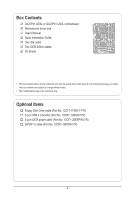
Box Contents GA-EP41-UD3L or GA-EP41-US3L motherboard Motherboard driver disk User's Manual Quick Installation Guide One IDE cable Two SATA 3Gb/s cables I/O Shield • The box contents above are for reference only and the actual items shall depend on the product - Gigabyte GA-EP41-UD3L | Manual - Page 7
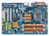
LPT COM R_USB LAN USB F_AUDIO AUDIO SYS_FAN1 PCIEX1_1 PCIEX16 RTL8111C/D(L) PCIEX1_2 CODEC PCIEX1_3 SPDIF_O CD_IN PCI1 SPDIF_I PCI2 IT8718 PCI3 FDD DDR2_1 DDR2_2 DDR2_3 DDR2_4 Intel® G41 ATX GA-EP41-UD3L/ GA-EP41-US3L CLR_CMOS BATTERY Intel® ICH7 SATA2_0 SATA2_2 SYS_FAN2 - Gigabyte GA-EP41-UD3L | Manual - Page 8
x1 PCIe CLK (100 MHz) PCI Bus LGA775 Processor CPU CLK+/(333/266/200 MHz) Host Interface Intel® G41 DDR2 800/667 MHz Dual Channel Memory GMCH CLK (333/266/200 MHz) Intel® ICH7 CODEC Dual BIOS ATA-100/66/33 IDE Channel 4 SATA 3Gb/s 8 USB Ports IT8718 Floppy LPT Port COM Port PS/2 KB/Mouse - Gigabyte GA-EP41-UD3L | Manual - Page 9
's manual and follow these procedures: • Prior to installation, do not remove or break motherboard S/N wrist strap when handling electronic com- ponents such as a motherboard, CPU or memory. If you do not have an ESD wrist steps or have a problem related to the use of the product, please consult - Gigabyte GA-EP41-UD3L | Manual - Page 10
® Celeron® processor in the LGA775 package (Go to GIGABYTE's website for the latest CPU support list.) L2 cache varies with CPU 1333/1066/800 MHz FSB North Bridge: Intel® G41 Express Chipset South Bridge: Intel® ICH7 4 x 1.8V DDR2 DIMM sockets supporting up to 8 GB of system memory (Note 1) Dual - Gigabyte GA-EP41-UD3L | Manual - Page 11
connector 4 x SATA 3Gb/s connectors 1 x CPU fan header 2 x system fan headers 1 x power fan header 1 x front panel header 1 x front panel audio header 1 x CD In connector 1 x S/PDIF In header 1 x S/PDIF Out header 2 x USB 2.0/1.1 headers 1 x power LED header 1 x chassis intrusion header 1 x clearing - Gigabyte GA-EP41-UD3L | Manual - Page 12
the DDR2_1 and DDR2_3 sockets. (Go to GIGABYTE's website for the latest memory support list.) (Note 3) Whether the CPU/system fan speed control function is supported will depend on the CPU/system cooler you install. (Note 4) Available functions in EasyTune may differ by motherboard model. Hardware - Gigabyte GA-EP41-UD3L | Manual - Page 13
before you begin to install the CPU: • Make sure that the motherboard supports the CPU. (Go to GIGABYTE's website for the latest CPU support list.) • Always turn off the computer and unplug the power cord from the power outlet before installing the CPU to prevent hardware damage. • Locate the - Gigabyte GA-EP41-UD3L | Manual - Page 14
below to correctly install the CPU into the motherboard CPU socket. Before installing the CPU, make sure to turn off the computer and unplug the power cord from the power outlet to prevent damage to the CPU. CPU Socket Lever Step 1: Completely raise the CPU socket lever. Step 2: Lift the metal - Gigabyte GA-EP41-UD3L | Manual - Page 15
pin. Check that the Male and Female push pins are joined closely. (Refer to your CPU cooler installation manual for instructions on installing the cooler.) Step 5: After the installation, check the back of the motherboard. If the push pin is inserted as the picture above shows, the installation is - Gigabyte GA-EP41-UD3L | Manual - Page 16
memory, switch the direction. 1-4-1 Dual Channel Memory Configuration This motherboard provides four DDR2 memory sockets and supports Dual Channel Technology. After the memory is installed, the BIOS will automatically detect the specifications and capacity of the memory. Enabling Dual Channel memory - Gigabyte GA-EP41-UD3L | Manual - Page 17
are not compatible to DDR DIMMs. Be sure to install DDR2 DIMMs on this motherboard. Notch DDR2 DIMM A DDR2 memory module has a notch, so it can only Spread the retaining clips at both ends of the memory socket. Place the memory module on the socket. As indicated in the picture on the left, place - Gigabyte GA-EP41-UD3L | Manual - Page 18
an expansion card: • Make sure the motherboard supports the expansion card. Carefully read the manual that came with your expansion card. • Always If necessary, go to BIOS Setup to make any required BIOS changes for your expansion card(s). 7. Install the driver provided with the expansion card - Gigabyte GA-EP41-UD3L | Manual - Page 19
audio in connector. Serial Port Use the serial port to connect devices such as a mouse, modem or other peripherals. USB Port The USB port supports the USB 2.0/1.1 specification. Use this port for USB devices such as a USB keyboard/mouse, USB printer, USB LED it from the motherboard. • When removing - Gigabyte GA-EP41-UD3L | Manual - Page 20
to perform different functions via the audio software. Only microphones still MUST be connected to the default Mic in jack ( ). Refer to the instructions on setting up a 2/4/5.1/7.1-channel audio configuration in Chapter 5, "Configuring 2/4/5.1/7.1-Channel Audio." Hardware Installation - 20 - - Gigabyte GA-EP41-UD3L | Manual - Page 21
devices. • After installing the device and before turning on the computer, make sure the device cable has been securely attached to the connector on the motherboard. - 21 - Hardware Installation - Gigabyte GA-EP41-UD3L | Manual - Page 22
supply can supply enough stable power to all the components on the motherboard. Before connecting the power connector, first make sure the power supply the correct orientation. The 12V power connector mainly supplies power to the CPU. If the 12V power connector is not connected, the computer will - Gigabyte GA-EP41-UD3L | Manual - Page 23
cable, be sure to connect it in the correct orientation (the black connector wire is the ground wire). The motherboard supports CPU fan speed control, which requires the use of a CPU fan with fan speed control design. For optimum heat dissipation, it is recommended that a system fan be installed - Gigabyte GA-EP41-UD3L | Manual - Page 24
configuring master/slave settings for the IDE devices, read the instructions from the device manufacturers.) 2 40 1 39 8) SATA2_0/1/2/3 3Gb/s standard and are compatible with SATA 1.5Gb/s standard. Each SATA connector supports a single SATA device. SATA2_0 7 1 SATA2_1 SATA2_2 1 7 SATA2_3 Pin - Gigabyte GA-EP41-UD3L | Manual - Page 25
/S4 sleep state or powered off (S5). Pin No. Definition 1 MPD+ 2 MPD- 1 3 MPD- System Status LED S0 On S1 Blinking S3/S4/S5 Off 10) BATTERY The battery provides power to keep the values (such as BIOS configurations, date, and time information) in the CMOS when the computer is turned off - Gigabyte GA-EP41-UD3L | Manual - Page 26
beep will be heard if no problem is detected at system startup. If a problem is detected, the BIOS may issue beeps in different patterns to indicate the problem. Refer to Chapter 5, "Troubleshooting," for information about beep codes. • HD (Hard Drive Activity LED, Blue) Connects to the hard drive - Gigabyte GA-EP41-UD3L | Manual - Page 27
NC • The front panel audio header supports HD audio by default. If your chassis provides an AC'97 front panel audio module, refer to the instructions on how to activate AC'97 functionality via the audio software in Chapter 5, "Configuring 2/4/5.1/7.1-Channel Audio." • Audio signals will be present - Gigabyte GA-EP41-UD3L | Manual - Page 28
Definition 1 Power 2 SPDIFI 1 3 GND 15) SPDIF_O (S/PDIF Out Header) This header supports digital S/PDIF Out and connects a S/PDIF digital audio cable (provided by expansion cards) for digital audio output from your motherboard to certain expansion cards like graphics cards and sound cards. For - Gigabyte GA-EP41-UD3L | Manual - Page 29
to turn off your computer and unplug the power cord from the power outlet to prevent damage to the USB bracket. 17) CI (Chassis Intrusion Header) This motherboard provides a chassis detection feature that detects if the chassis cover has been removed. This function requires a chassis with chassis - Gigabyte GA-EP41-UD3L | Manual - Page 30
motherboard. • After system restart, go to BIOS Setup to load factory defaults (select Load Optimized Defaults) or manually configure the BIOS settings (refer to Chapter 2, "BIOS Setup," for BIOS configurations). 19) PHASE LED The number of lighted LEDs indicates the CPU loading. The higher the CPU - Gigabyte GA-EP41-UD3L | Manual - Page 31
Windows-based utility that searches and downloads the latest version of BIOS from the Internet and updates the BIOS. For instructions on using the Q-Flash and @BIOS utilities, refer to Chapter 4, "BIOS Update Utilities." • Because BIOS flashing is potentially risky, if you do not encounter problems - Gigabyte GA-EP41-UD3L | Manual - Page 32
v6.00PG, An Energy Star Ally Copyright (C) 1984-2009, Award Software, Inc. Motherboard Model BIOS Version EP41-UD3L F2e . . . . : BIOS Setup : XpressRecovery2 : Boot Menu : Qflash 03/11/2009-G41-ICH7-7A69PG0OC-00 Function Keys Function Keys Function Keys: : POST SCREEN - Gigabyte GA-EP41-UD3L | Manual - Page 33
BIOS Version: GA-EP41-UD3L F2e) CMOS Setup Utility-Copyright (C) 1984-2009 Award Software MB Intelligent Tweaker(M.I.T.) Standard CMOS Features Advanced BIOS Save & Exit Setup Change CPU's Clock & Voltage F11: Save CMOS to BIOS F12: Load CMOS from BIOS BIOS Setup Program Function Keys - Gigabyte GA-EP41-UD3L | Manual - Page 34
. Advanced BIOS Features Use this menu to configure the device boot order, advanced features available on the CPU, and the primary display adapter. Integrated Peripherals Use this menu to configure all peripheral devices, such as IDE, SATA, USB, integrated audio, and integrated LAN, etc. Power - Gigabyte GA-EP41-UD3L | Manual - Page 35
(C) 1984-2009 Award Software MB Intelligent Tweaker(M.I.T.) overclock/overvoltage may result in damage to CPU, chipset, boot. If this occurs, clear the CMOS values and reset the board to default values.) (Note) This item appears only if you install a CPU that supports this feature. - 35 - BIOS - Gigabyte GA-EP41-UD3L | Manual - Page 36
boot after overclocking, please wait for 20 seconds to allow for automated system reboot, or clear the CMOS values to reset the board to default values. (Default: Disabled) CPU Host Frequency (Mhz) Allows you to manually set the CPU if you install a CPU that supports this feature. BIOS Setup - 36 - - Gigabyte GA-EP41-UD3L | Manual - Page 37
adjusted according to the CPU Host Frequency (Mhz) and System Memory Multiplier settings. DRAM Timing Selectable (SPD) Manual allows all DRAM Advanced Timing Control CMOS Setup Utility-Copyright (C) 1984-2009 Award Software Advanced Timing Control x tRRD x tWTR x tWR x tRFC - Gigabyte GA-EP41-UD3L | Manual - Page 38
Channel A/B Channel A/B Timing Settings CMOS Setup Utility-Copyright (C) 1984-2009 Award Software Channel A/B Timing Settings x Static tRead Value x tRD Phase0 Adjustment x tRD Phase1 (default), 0-Normal, 1-Advanced. ESC: Exit F1: General Help F7: Optimized Defaults BIOS Setup - 38 - - Gigabyte GA-EP41-UD3L | Manual - Page 39
enhance memory compatibility. Auto Lets the BIOS decide whether to enable this function. Setup Utility-Copyright (C) 1984-2009 Award Software Channel A/B Driving Settings x Driving Strength are: Auto (default), 667MHz, 800MHz, 1066MHz, OC-1200, OC-1333. Data Driving Pull-Up Level Options are: - Gigabyte GA-EP41-UD3L | Manual - Page 40
are: Auto (default), +8~-7. Clk Driving Pull-Down Level Options are: Auto (default), +8~-7. ******** Mother Board Voltage Control CPU CPU Vcore The default is Auto. CPU Termination The default is Auto. CPU Reference The default is Auto. >>> MCH/ICH MCH Core The default is Auto. ICH I/O The default - Gigabyte GA-EP41-UD3L | Manual - Page 41
Award Software Standard CMOS [None] Drive A Floppy 3 Mode Support [1.44M, 3.5"] [Disabled] Halt On the three methods below: • Auto Lets BIOS automatically detect IDE/SATA devices during the POST system startup. • Manual Allows you to manually enter the specifications of the hard - Gigabyte GA-EP41-UD3L | Manual - Page 42
specifications. If you wish to enter the parameters manually 1.44M/3.5", 2.88M/3.5". Floppy 3 Mode Support Allows you to specify whether the installed BIOS detects a non-fatal error the system boot will stop. No Errors The system boot will not stop for any error. All, But Keyboard The system boot - Gigabyte GA-EP41-UD3L | Manual - Page 43
CMOS Setup Utility-Copyright (C) 1984-2009 Award Software Advanced BIOS Features } Hard Disk Boot Priority First Boot Device Second Boot Device Third Boot Device Password Check HDD S.M.A.R.T. Capability CPU Multi-Threading (Note) Limit CPUID Max. to 3 (Note) No-Execute - Gigabyte GA-EP41-UD3L | Manual - Page 44
Execute Disable Bit function. This function may enhance protection for the computer, reducing exposure to viruses and malicious buffer overflow attacks when working with its supporting software and system. (Default: Enabled) CPU Enhanced Halt (C1E) (Note) Enables or disables Intel CPU Enhanced Halt - Gigabyte GA-EP41-UD3L | Manual - Page 45
Full Screen LOGO Show Allows you to determine whether to display the GIGABYTE Logo at system startup. Disabled displays normal POST message. (Default: Enabled) Init Display First Specifies first display. (Default) PEG Sets the PCI Express graphics card as the first display. - 45 - BIOS Setup - Gigabyte GA-EP41-UD3L | Manual - Page 46
Boot ROM Onboard Serial Port 1 Onboard Parallel Port Parallel Port Mode USB 1.0 Controller USB 2.0 Controller USB Keyboard Function USB Mouse Function USB Auto Lets the BIOS set SATA devices to to Combined mode, you can manually re-configure it to Enhanced mode - Gigabyte GA-EP41-UD3L | Manual - Page 47
-Copyright (C) 1984-2009 Award Software SMART LAN Start detecting at LAN cable is attached to the motherboard, the Status fields of all four Is Functioning Normally... If no cable problem is detected on the LAN cable connected Windows mode or when the LAN Boot ROM is activated. - 47 - BIOS Setup - Gigabyte GA-EP41-UD3L | Manual - Page 48
Allows USB keyboard to be used in MS-DOS. (Default: Disabled) USB Mouse Function Allows USB mouse to be used in MS-DOS. (Default: Disabled) USB Storage Function Determines whether to detect USB storage devices, including USB flash drives and USB hard drives during the POST. (Default: Enabled) BIOS - Gigabyte GA-EP41-UD3L | Manual - Page 49
any time. S3(STR) Enables the system to enter the ACPI S3 (Suspend to RAM) sleep state (default). In S3 sleep state, the system appears to be off signal from a modem that supports wake-up function. (Default: Enabled) (Note) Supported on Windows Vista operating system only. - 49 - BIOS Setup - Gigabyte GA-EP41-UD3L | Manual - Page 50
system at a specific time on each day or on a specific day in a Windows Vista operating system. Select 32-bit mode when you install 32-bit Windows Vista; select 64-bit mode when you install 64-bit Windows Vista. This item is configurable only if the HPET Support is set to Enabled. (Default: 32-bit - Gigabyte GA-EP41-UD3L | Manual - Page 51
PCI Configurations CMOS Setup Utility-Copyright (C) 1984-2009 Award Software PnP/PCI Configurations PCI1 IRQ Assignment PCI2 IRQ Assignment PCI3 ,14,15 PCI3 IRQ Assignment Auto 3,4,5,7,9,10,11,12,14,15 BIOS auto-assigns IRQ to the first PCI slot. (Default) Assigns IRQ 3,4,5,7,9,10,11 - Gigabyte GA-EP41-UD3L | Manual - Page 52
Status CMOS Setup Utility-Copyright (C) 1984-2009 Award Software PC Health Status Reset Case Open Status Case Opened Vcore DDR18V +3.3V +12V Current System Temperature Current CPU Temperature Current CPU FAN Speed Current SYSTEM FAN2 Speed Current POWER FAN - Gigabyte GA-EP41-UD3L | Manual - Page 53
may try to load Fail-Safe defaults, which are the safest and most stable BIOS settings for the motherboard. 2-11 Load Optimized Defaults CMOS Setup Utility-Copyright (C) 1984-2009 Award Software MB Intelligent Tweaker(M.I.T.) Load Fail-Safe Defaults Standard CMOS Features Load Optimized - Gigabyte GA-EP41-UD3L | Manual - Page 54
(C) 1984-2009 Award Software MB Intelligent Tweaker(M.I.T.) Standard CMOS Features Advanced BIOS Features Integrated Peripherals boot. In BIOS Setup, you must enter the supervisor password if you wish to make changes to BIOS settings. The user password only allows you to view the BIOS - Gigabyte GA-EP41-UD3L | Manual - Page 55
. This saves the changes to the CMOS and exits the BIOS Setup program. Press or to return to the BIOS Setup Main Menu. 2-14 Exit Without Saving CMOS Setup Utility-Copyright (C) 1984-2009 Award Software MB Intelligent Tweaker(M.I.T.) Load Fail-Safe Defaults Standard CMOS Features - Gigabyte GA-EP41-UD3L | Manual - Page 56
BIOS Setup - 56 - - Gigabyte GA-EP41-UD3L | Manual - Page 57
are installed, follow the on-screen instructions to restart your system. You can install other applications included in the motherboard driver disk. • For USB 2.0 driver support under the Windows XP operating system, please install the Windows XP Service Pack 1 or later. After installing the SP1 - Gigabyte GA-EP41-UD3L | Manual - Page 58
applications that GIGABYTE develops and some free software. You can click the Install button on the right of an item to install it. 3-3 Technical Manuals This page provides GIGABYTE's application guides, content descriptions for this driver disk, and the motherboard manuals. Drivers Installation - Gigabyte GA-EP41-UD3L | Manual - Page 59
3-4 Contact For the detailed contact information of the GIGABYTE Taiwan headquarter or worldwide branch offices, click the URL on this page to link to the GIGABYTE website. 3-5 System This page provides the basic system information. - 59 - Drivers Installation - Gigabyte GA-EP41-UD3L | Manual - Page 60
3-6 Download Center To update the BIOS, drivers, or applications, click the Download Center button to link to the GIGABYTE website. The latest version of the BIOS, drivers, or applications will be displayed. Drivers Installation - 60 - - Gigabyte GA-EP41-UD3L | Manual - Page 61
Recovery cannot be restored using Xpress Recovery2. • USB hard drives are not supported. • Hard drives in RAID/AHCI mode are not supported. Installation and Configuration: Turn on your system to boot from the Windows Vista setup disk. A. Installing Windows Vista and Partitioning the Hard Drive Step - Gigabyte GA-EP41-UD3L | Manual - Page 62
the top). Please note that if there is no enough unallocated space, Xpress Recovery2 cannot save the backup file. B. Accessing Xpress Recovery2 1. Boot from the motherboard driver disk to access Xpress Recovery2 for the first time. When you see the following message: Press any key to startup Xpress - Gigabyte GA-EP41-UD3L | Manual - Page 63
D. Using the Restore Function in Xpress Recovery2 Select RESTORE to restore the backup to your hard drive in case the system breaks down. The RESTORE option will not be present if no backup is created before. E. Removing the Backup Step 1: If you wish to remove the backup file, select REMOVE. Step - Gigabyte GA-EP41-UD3L | Manual - Page 64
However, if the BIOS update file is saved to a hard drive in RAID/AHCI mode or a hard drive attached to an independent IDE/SATA controller, use the key during the POST to access Q-Flash. Award Modular BIOS v6.00PG, An Energy Star Ally Copyright (C) 1984-2009, Award Software, Inc. EP41-UD3L F2e - Gigabyte GA-EP41-UD3L | Manual - Page 65
key to select Update BIOS from Drive and press . • The Save Main BIOS to Drive option allows you to save the current BIOS file. • Q-Flash only supports USB flash drive or hard drives using FAT32/16/12 file system. • If the BIOS update file is saved to a hard drive in RAID/AHCI mode or a hard - Gigabyte GA-EP41-UD3L | Manual - Page 66
Load Optimized Defaults and press to load BIOS defaults. System will re-detect all peripheral devices after a BIOS update, so we recommend that you reload BIOS defaults. CMOS Setup Utility-Copyright (C) 1984-2009 Award Software MB Intelligent Tweaker(M.I.T.) Load Fail-Safe Defaults - Gigabyte GA-EP41-UD3L | Manual - Page 67
. If the BIOS update file for your motherboard is not present on the @BIOS server site, please manually download the BIOS update file from GIGABYTE's website and follow the instructions in "Update the BIOS without Using the Internet Update Function" below. 2. Update the BIOS without Using the - Gigabyte GA-EP41-UD3L | Manual - Page 68
functions in EasyTune 6 may differ by motherboard model. Grayed-out area(s) indicates that the item is not configurable or the function is not supported. Incorrectly doing overclock/overvoltage may result in damage to the hardware components such as CPU, chipset, and memory and reduce the useful - Gigabyte GA-EP41-UD3L | Manual - Page 69
, GIGABYTE Dynamic Energy Saver Advanced shows how much power they have saved in a set period of time. Meter Mode - Button Information Table Button Description 1 Dynamic Energy Saver On/Off Switch (Default: Off) 2 Motherboard Phase LED On/Off Switch (Default: On) 3 Dynamic CPU Frequency - Gigabyte GA-EP41-UD3L | Manual - Page 70
(Default: Off) 2 Motherboard Phase LED On/Off Switch (Default: On) 3 Dynamic CPU Frequency Function On/Off Switch (Default: Off) 4 CPU Throttling Display 5 3-Level CPU Voltage Switch (Default:1) (Note 3) 6 CPU Voltage Display 7 Dynamic Power Phase Status 8 Current CPU Power Consumption - Gigabyte GA-EP41-UD3L | Manual - Page 71
for using Q-Share After installing Q-Share from the motherboard driver disk, go to Start>All Programs>GIGABYTE>Q-Share.exe to launch the Q-Share tool. Find shared data folder Changes the data folder to be shared (Note) Updates Q-Share online Displays the current Q-Share version Exits Q-Share ( - Gigabyte GA-EP41-UD3L | Manual - Page 72
Services technology, Time Repair allows you to quickly back up and restore your system data in the Windows Vista operating system. Time Repair supports system restore point upon the first boot up of the day Displays the . • Each storage volume can accommodate 64 shadow copies. When this limit is - Gigabyte GA-EP41-UD3L | Manual - Page 73
over the Internet, and etc. all at the same time. A. Configuring Speakers (The following instructions use Windows Vista as the example operating system.) Step 1: After installing the audio driver, the HD Audio Manager icon will appear in the notification area. Double-click the icon to access the HD - Gigabyte GA-EP41-UD3L | Manual - Page 74
tab. In the Speaker Configuration list, select Stereo, Quadraphonic, 5.1 Speaker, or 7.1 Speaker according to the type of speaker configuration you wish to set up. Then the speaker setup is completed. B. Configuring Sound Effect You may configure an audio environment on the Sound Effects tab - Gigabyte GA-EP41-UD3L | Manual - Page 75
allows you to input digital audio signals to the computer for audio processing. S/PDIF In Cable Optical S/PDIF In Coaxial S/PDIF In 1. Installing the S/PDIF In Cable: Step 1: First, attach the connector at the end of the cable to the SPDIF_I header on your motherboard. Step 2: Secure the metal - Gigabyte GA-EP41-UD3L | Manual - Page 76
Out The S/PDIF Out jacks can transmit audio signals to an external decoder for decoding to get the best audio quality. 1. Connecting a S/PDIF Out Cable (either one) to an external decoder for transmitting the S/PDIF digital audio signals. 2. Configuring S/PDIF Out: On the Digital Output screen, - Gigabyte GA-EP41-UD3L | Manual - Page 77
5-1-3 Configuring Microphone Recording Step 1: After installing the audio driver, the HD Audio Manager icon will appear in the notification area. Double-click the icon to access the HD Audio Manager. Step 2: Connect your microphone to the Mic in jack (pink) on the back panel or the Mic in jack (pink - Gigabyte GA-EP41-UD3L | Manual - Page 78
, click Start, point to All Programs, point to Accessories, and then click Sound Recorder to begin the sound recording. * Enabling Stereo Mix If the HD Audio Manager does not display the recording device you wish to use, refer to the steps below. The following steps explain how to enable Stereo Mix - Gigabyte GA-EP41-UD3L | Manual - Page 79
the Start Recording button . 3. To stop recording audio, click the Stop Recording button . Be sure to save the recorded audio file upon completion. B. Playing the Recorded Sound You can play your recording in a digital media player program that supports your audio file format. - 79 - Appendix - Gigabyte GA-EP41-UD3L | Manual - Page 80
5-2 Troubleshooting 5-2-1 Frequently Asked Questions To read more FAQs for your motherboard, please go to the Support&Downloads\Motherboard\FAQ page on GIGABYTE's website. Q: In the BIOS Setup program, why are some BIOS options missing? A: Some advanced options are hidden in the BIOS Setup program - Gigabyte GA-EP41-UD3L | Manual - Page 81
Procedure If you encounter any troubles during system startup, follow the troubleshooting procedure below to solve the problem. START Turn off the power. Remove all peripherals, connecting cables, and power cord etc. Make sure the motherboard does not short-circuit with the chassis or - Gigabyte GA-EP41-UD3L | Manual - Page 82
and solved. END If the procedure above is unable to solve your problem, contact the place of purchase or local dealer for help. Or go to the Support&Downloads\Technical Service Zone page to submit your question. Our customer service staff will reply you as soon as possible. Appendix - 82 - - Gigabyte GA-EP41-UD3L | Manual - Page 83
GIGABYTE. Our Commitment to Preserving the Environment In addition to high-efficiency performance, all GIGABYTE motherboards office, your household waste disposal service or where you purchased the product Customer Care number listed in your product's user's manual and we will be glad to help you - Gigabyte GA-EP41-UD3L | Manual - Page 84
Finally, we suggest that you practice other environmentally friendly actions by understanding and using the energy-saving features of this product (where applicable), recycling the inner and outer packaging (including shipping containers) this product was delivered in, and by disposing of or - Gigabyte GA-EP41-UD3L | Manual - Page 85
- 85 - Appendix - Gigabyte GA-EP41-UD3L | Manual - Page 86
Appendix - 86 - - Gigabyte GA-EP41-UD3L | Manual - Page 87
231, Taiwan TEL: +886-2-8912-4000 FAX: +886-2-8912-4003 Tech. and Non-Tech. Support (Sales/Marketing) : http://ggts.gigabyte.com.tw WEB address (English): http://www.gigabyte.com.tw WEB address (Chinese): http://www.gigabyte.tw • G.B.T. INC. - U.S.A. TEL: +1-626-854-9338 FAX: +1-626-854-9339 Tech - Gigabyte GA-EP41-UD3L | Manual - Page 88
.co.yu • Kazakhstan WEB address : http://www.giga-byte.kz You may go to the GIGABYTE website, select your language in the language list on the top right corner of the website. • GIGABYTE Global Service System To submit a technical or non-technical (Sales/Marketing) question, please link to: http
-
 1
1 -
 2
2 -
 3
3 -
 4
4 -
 5
5 -
 6
6 -
 7
7 -
8
-
9
-
10
-
11
-
12
-
13
-
14
-
15
-
16
-
17
-
18
-
19
-
20
-
21
-
22
-
23
-
24
-
25
-
26
-
27
-
28
-
29
-
30
-
31
-
32
-
33
-
34
-
35
-
36
-
37
-
38
-
39
-
40
-
41
-
42
-
43
-
44
-
45
-
46
-
47
-
48
-
49
-
50
-
51
-
52
-
53
-
54
-
55
-
56
-
57
-
58
-
59
-
60
-
61
-
62
-
63
-
64
-
65
-
66
-
67
-
68
-
69
-
70
-
71
-
72
-
73
-
74
-
75
-
76
-
77
-
78
-
79
-
80
-
81
-
82
-
83
-
84
-
85
-
86
-
87
-
88
 |
 |

GA-EP41-UD3L
GA-EP41-US3L
LGA775 socket motherboard for Intel
®
Core
™
processor family/
Intel
®
Pentium
®
processor family/Intel
®
Celeron
®
processor family
User's Manual
Rev. 1003
12ME-EP41UD3L-1003R