Gigabyte GA-EP41T-UD3L Manual
Gigabyte GA-EP41T-UD3L Manual
 |
View all Gigabyte GA-EP41T-UD3L manuals
Add to My Manuals
Save this manual to your list of manuals |
Gigabyte GA-EP41T-UD3L manual content summary:
- Gigabyte GA-EP41T-UD3L | Manual - Page 1
GA-EP41T-UD3L LGA775 socket motherboard for Intel® Core™ processor family/ Intel® Pentium® processor family/Intel® Celeron® processor family User's Manual Rev. 1101 12ME-41TUD3L-1101R - Gigabyte GA-EP41T-UD3L | Manual - Page 2
Motherboard GA-EP41T-UD3L Nov. 12, 2009 Motherboard GA-EP41T-UD3L Nov. 12, 2009 - Gigabyte GA-EP41T-UD3L | Manual - Page 3
at: http://www.gigabyte.com.tw Identifying Your Motherboard Revision The revision number on your motherboard looks like this: "REV: X.X." For example, "REV: 1.0" means the revision of the motherboard is 1.0. Check your motherboard revision before updating motherboard BIOS, drivers, or when looking - Gigabyte GA-EP41T-UD3L | Manual - Page 4
Items...6 GA-EP41T-UD3L Motherboard Layout 7 Block Diagram...8 Chapter 1 Hardware Installation 9 1-1 Installation Precautions 9 1-2 Product Specifications 10 1-3 Installing the CPU and CPU Cooler 13 1-3-1 Installing the CPU 13 1-3-2 Installing the CPU Cooler 15 1-4 Installing the Memory 16 - Gigabyte GA-EP41T-UD3L | Manual - Page 5
Drivers 57 3-2 Application Software 58 3-3 Technical Manuals 58 3-4 Contact...59 3-5 System...59 3-6 Download Center 60 Chapter 4 Unique Features 61 4-1 Xpress Recovery2 61 4-2 BIOS Update Utilities 64 4-2-1 Updating the BIOS with the Q-Flash Utility 64 4-2-2 Updating the BIOS with the @BIOS - Gigabyte GA-EP41T-UD3L | Manual - Page 6
Box Contents GA-EP41T-UD3L motherboard Motherboard driver disk User's Manual Quick Installation Guide One IDE cable Two SATA 3Gb/s cables I/O Shield • The box contents above are for reference only and the actual items shall depend on the product - Gigabyte GA-EP41T-UD3L | Manual - Page 7
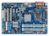
GA-EP41T-UD3L Motherboard Layout LPT KB_MS Coaxial Optical ATX_12V LGA775 PHASE_LED CPU_FAN PWR_FAN COM R_USB LAN USB F_AUDIO AUDIO SYS_FAN1 PCIEX1_1 RTL8111D PCIEX16 PCIEX1_2 CODEC PCIEX1_3 SPDIF_O CD_IN PCI1 SPDIF_I PCI2 IT8718 PCI3 FDD DDR3_1 DDR3_2 DDR3_3 DDR3_4 Intel - Gigabyte GA-EP41T-UD3L | Manual - Page 8
Express Bus 3 PCI Express x1 x1 LAN RJ45 RTL8111D x1 x1 x1 PCIe CLK (100 MHz) PCI Bus LGA775 CPU CPU CLK+/(333/266/200 MHz) Host Interface Intel® G41 DDR3 1333 (O.C.)/1066/800 MHz Dual Channel Memory GMCH CLK (333/266/200 MHz) Intel® ICH7 CODEC Dual BIOS ATA-100/66/33 IDE Channel 4 SATA - Gigabyte GA-EP41T-UD3L | Manual - Page 9
discharge (ESD) wrist strap when handling electronic com- ponents such as a motherboard, CPU or memory. If you do not have an ESD wrist strap, keep your hands dry uncertain about any installation steps or have a problem related to the use of the product, please consult a certified computer technician - Gigabyte GA-EP41T-UD3L | Manual - Page 10
channel memory architecture (Note 2) w Support for DDR3 1333 (O.C.)/1066/800 MHz memory modules (Go to GIGABYTE's website for the latest memory support list.) Realtek ALC888 codec High Definition Audio 2/4/5.1/7.1-channel Support for S/PDIF In/Out Support for CD In LAN 1 x RTL8111D - Gigabyte GA-EP41T-UD3L | Manual - Page 11
w w w 1 x 24-pin ATX main power connector 1 x 4-pin ATX 12V power connector 1 x floppy disk drive connector 1 x IDE connector 4 x SATA 3Gb/s connectors 1 x CPU fan header 2 x system fan headers 1 x power fan header 1 x front panel header 1 x front panel audio header 1 x CD In connector - Gigabyte GA-EP41T-UD3L | Manual - Page 12
sockets. (Go to GIGABYTE's website for the latest memory support list.) (Note 3) Whether the CPU/system fan speed control function is supported will depend on the CPU/system cooler you install. (Note 4) Available functions in EasyTune may differ by motherboard model. Hardware Installation - 12 - Gigabyte GA-EP41T-UD3L | Manual - Page 13
do so according to your hardware specifications including the CPU, graphics card, memory, hard drive, etc. 1-3-1 Installing the CPU A. Locate the alignment keys on the motherboard CPU socket and the notches on the CPU. LGA775 CPU Socket Alignment Key LGA775 CPU Alignment Key Pin One Corner of - Gigabyte GA-EP41T-UD3L | Manual - Page 14
the steps below to correctly install the CPU into the motherboard CPU socket. Before installing the CPU, make sure to turn off the computer and unplug the power cord from the power outlet to prevent damage to the CPU. CPU Socket Lever Step 1: Completely raise the CPU socket lever. Step 2: Lift the - Gigabyte GA-EP41T-UD3L | Manual - Page 15
pin. Check that the Male and Female push pins are joined closely. (Refer to your CPU cooler installation manual for instructions on installing the cooler.) Step 5: After the installation, check the back of the motherboard. If the push pin is inserted as the picture above shows, the installation is - Gigabyte GA-EP41T-UD3L | Manual - Page 16
This motherboard provides four DDR3 memory sockets and supports Dual Channel Technology. After the memory is installed, the BIOS will automatically detect the specifications and capacity of the memory. Enabling Dual Channel memory mode will double the original memory bandwidth. The four DDR3 memory - Gigabyte GA-EP41T-UD3L | Manual - Page 17
unplug the power cord from the power outlet to prevent damage to the memory module. DDR3 and DDR2 DIMMs are not compatible to each other or DDR DIMMs. Be sure to install DDR3 DIMMs on this motherboard. Notch DDR3 DIMM A DDR3 memory module has a notch, so it can only fit in one direction. Follow the - Gigabyte GA-EP41T-UD3L | Manual - Page 18
an expansion card: • Make sure the motherboard supports the expansion card. Carefully read the manual that came with your expansion card. • Always If necessary, go to BIOS Setup to make any required BIOS changes for your expansion card(s). 7. Install the driver provided with the expansion card - Gigabyte GA-EP41T-UD3L | Manual - Page 19
audio in connector. Serial Port Use the serial port to connect devices such as a mouse, modem or other peripherals. USB Port The USB port supports the USB 2.0/1.1 specification. Use this port for USB devices such as a USB keyboard/mouse, USB printer, USB flash drive and etc. RJ-45 LAN motherboard. - Gigabyte GA-EP41T-UD3L | Manual - Page 20
to perform different functions via the audio software. Only microphones still MUST be connected to the default Mic in jack ( ). Refer to the instructions on setting up a 2/4/5.1/7.1-channel audio configuration in Chapter 5, "Configuring 2/4/5.1/7.1-Channel Audio." Hardware Installation - 20 - - Gigabyte GA-EP41T-UD3L | Manual - Page 21
devices. • After installing the device and before turning on the computer, make sure the device cable has been securely attached to the connector on the motherboard. - 21 - Hardware Installation - Gigabyte GA-EP41T-UD3L | Manual - Page 22
connector in the correct orientation. The 12V power connector mainly supplies power to the CPU. If the 12V power connector is not connected, the a 2x12 power supply, remove the protective cover from the main power connector on the motherboard. Do not insert the power supply cable into pins under - Gigabyte GA-EP41T-UD3L | Manual - Page 23
cable, be sure to connect it in the correct orientation (the black connector wire is the ground wire). The motherboard supports CPU fan speed control, which requires the use of a CPU fan with fan speed control design. For optimum heat dissipation, it is recommended that a system fan be installed - Gigabyte GA-EP41T-UD3L | Manual - Page 24
configuring master/slave settings for the IDE devices, read the instructions from the device manufacturers.) 2 40 1 39 8) SATA2_0/1/2/3 3Gb/s standard and are compatible with SATA 1.5Gb/s standard. Each SATA connector supports a single SATA device. SATA2_0 7 1 SATA2_1 SATA2_2 1 7 SATA2_3 Pin - Gigabyte GA-EP41T-UD3L | Manual - Page 25
problem is detected at system startup. If a problem is detected, the BIOS may issue beeps in different patterns to indicate the problem. Refer to Chapter 5, "Troubleshooting panel design may differ by chassis. A front panel module mainly consists of power switch, reset switch, power LED, hard drive - Gigabyte GA-EP41T-UD3L | Manual - Page 26
NC • The front panel audio header supports HD audio by default. If your chassis provides an AC'97 front panel audio module, refer to the instructions on how to activate AC'97 functionality via the audio software in Chapter 5, "Configuring 2/4/5.1/7.1-Channel Audio." • Audio signals will be present - Gigabyte GA-EP41T-UD3L | Manual - Page 27
Definition 1 Power 2 SPDIFI 1 3 GND 13) SPDIF_O (S/PDIF Out Header) This header supports digital S/PDIF Out and connects a S/PDIF digital audio cable (provided by expansion cards) for digital audio output from your motherboard to certain expansion cards like graphics cards and sound cards. For - Gigabyte GA-EP41T-UD3L | Manual - Page 28
USB Headers) The headers conform to USB 2.0/1.1 specification. Each USB header can provide two USB ports motherboard. • After system restart, go to BIOS Setup to load factory defaults (select Load Optimized Defaults) or manually configure the BIOS settings (refer to Chapter 2, "BIOS Setup," for BIOS - Gigabyte GA-EP41T-UD3L | Manual - Page 29
Battery) The battery provides power to keep the values (such as BIOS configurations, date, and time information) in the CMOS when the regulations. 17) PHASE LED The number of lighted LEDs indicates the CPU loading. The higher the CPU loading, the more the number of lighted LEDs. To enable the - Gigabyte GA-EP41T-UD3L | Manual - Page 30
Hardware Installation - 30 - - Gigabyte GA-EP41T-UD3L | Manual - Page 31
the GIGABYTE Q-Flash or @BIOS utility. • Q-Flash allows the user to quickly and easily upgrade or back up BIOS without entering the operating system. • @BIOS is a Windows-based utility that searches and downloads the latest version of BIOS from the Internet and updates the BIOS. For instructions on - Gigabyte GA-EP41T-UD3L | Manual - Page 32
computer boots. A. The LOGO Screen (Default) B. The POST Screen Award Modular BIOS v6.00PG, An Energy Star Ally Copyright (C) 1984-2009, Award Software, Inc. Motherboard Model BIOS Version EP41T-UD3L E4 . . . . : BIOS Setup : XpressRecovery2 : Boot Menu : Qflash 09/21/2009 - Gigabyte GA-EP41T-UD3L | Manual - Page 33
Quit F8: Q-Flash Select Item F10: Save & Exit Setup Change CPU's Clock & Voltage F11: Save CMOS to BIOS F12: Load CMOS from BIOS BIOS Setup Program of the submenu. • If you do not find the settings you want in the Main Menu or a submenu, press + to access more advanced options. • - Gigabyte GA-EP41T-UD3L | Manual - Page 34
. Advanced BIOS Features Use this menu to configure the device boot order, advanced features available on the CPU, and the primary display adapter. Integrated Peripherals Use this menu to configure all peripheral devices, such as IDE, SATA, USB, integrated audio, and integrated LAN, etc. Power - Gigabyte GA-EP41T-UD3L | Manual - Page 35
is dependent on your overall system configurations. Incorrectly doing overclock/overvoltage may result in damage to CPU, chipset, or memory and reduce the useful life of these components. This values.) (Note) This item appears only if you install a CPU that supports this feature. - 35 - BIOS Setup - Gigabyte GA-EP41T-UD3L | Manual - Page 36
Important: It is highly recommended that the CPU frequency be set in accordance with the CPU specifications. PCI Express Frequency (Mhz) Allows you to manually set the PCIe clock frequency. The adjustable range item appears only if you install a CPU that supports this feature. BIOS Setup - 36 - - Gigabyte GA-EP41T-UD3L | Manual - Page 37
memory multiplier. Options are dependent on CPU FSB and the (G)MCH Frequency Latch settings. Auto sets memory multiplier according to memory SPD data. (Default: Auto) Memory Frequency (Mhz) The first memory Fail-Safe Defaults ESC: Exit F1: General Help F7: Optimized Defaults - 37 - BIOS Setup - Gigabyte GA-EP41T-UD3L | Manual - Page 38
Phase2 Adjustment Options are: Auto (default), 0-Normal, 1-Advanced. tRD Phase3 Adjustment Options are: Auto (default), 0-Normal, 1-Advanced. ESC: Exit F1: General Help F7: Optimized Defaults BIOS Setup - 38 - - Gigabyte GA-EP41T-UD3L | Manual - Page 39
are: Auto (default), +800ps~-700ps. DDR Write Training Allows you to determine whether to fine-tune memory parameters to enhance memory compatibility. Auto Lets the BIOS decide whether to enable this function. (Default) Disabled Disables this function. Enabled Enables this function to enhance - Gigabyte GA-EP41T-UD3L | Manual - Page 40
are: Auto (default), +8~-7. Clk Driving Pull-Down Level Options are: Auto (default), +8~-7. ******** Mother Board Voltage Control CPU CPU Vcore The default is Auto. CPU Termination The default is Auto. CPU Reference The default is Auto. >>> MCH/ICH MCH Core The default is Auto. ICH I/O The default - Gigabyte GA-EP41T-UD3L | Manual - Page 41
BIOS automatically detect IDE/SATA devices during the POST. (Default) • None If no IDE/SATA devices are used, set this item to None so the system will skip the detection of the device during the POST for faster system startup. • Manual Allows you to manually enter the specifications - Gigabyte GA-EP41T-UD3L | Manual - Page 42
25", 1.2M/5.25", 720K/3.5", 1.44M/3.5", 2.88M/3.5". Floppy 3 Mode Support Allows you to specify whether the installed floppy disk drive is 3-mode floppy other errors. Memory These fields are read-only and are determined by the BIOS POST. Base Memory Also called conventional memory. Typically, 640 - Gigabyte GA-EP41T-UD3L | Manual - Page 43
. to 3 (Note) No-Execute Memory Protect (Note) CPU Enhanced Halt (C1E) (Note) C2/C2E State Support (Note) CPU Thermal Monitor 2(TM2) (Note) CPU EIST Function (Note) Virtualization Technology (Note) Delay For HDD (Secs) Full Screen LOGO Show Backup BIOS Image to HDD Init Display - Gigabyte GA-EP41T-UD3L | Manual - Page 44
systems that support multi-processor mode. Enabled Enables all CPU cores and multi-threading capability. (Default) Disabled Enables only one CPU core. Limit CPUID Max. to 3 (Note) Allows you to determine whether to limit CPUID maximum value. Set this item to Disabled for Windows XP operating - Gigabyte GA-EP41T-UD3L | Manual - Page 45
Show Allows you to determine whether to display the GIGABYTE Logo at system startup. Disabled displays normal POST message. (Default: Enabled) Backup BIOS Image to HDD Allows the system to copy the BIOS image file to the hard drive. If the system BIOS is corrupted, it will be recovered from this - Gigabyte GA-EP41T-UD3L | Manual - Page 46
to Azalia Codec Onboard H/W LAN Green LAN } SMART LAN Onboard LAN Boot ROM Onboard Serial Port SATA controller. Auto Lets the BIOS set SATA devices to Combined or is automatically configured to Combined mode, you can manually re-configure it to Enhanced mode as needed - Gigabyte GA-EP41T-UD3L | Manual - Page 47
Is Attached... If no LAN cable is attached to the motherboard, the Status fields of all four pairs of wires will show Open and the Length fields show 0m, as shown in the figure above. When LAN Cable Is Functioning Normally... If no cable problem is detected on the LAN cable connected to a Gigabit - Gigabyte GA-EP41T-UD3L | Manual - Page 48
approximate length of the attached LAN cable. Onboard LAN Boot ROM Allows you to decide whether to activate the boot ROM integrated with the onboard LAN chip. (Default: Disabled) storage devices, including USB flash drives and USB hard drives during the POST. (Default: Enabled) BIOS Setup - 48 - - Gigabyte GA-EP41T-UD3L | Manual - Page 49
any time. S3(STR) Enables the system to enter the ACPI S3 (Suspend to RAM) sleep state (default). In S3 sleep state, the system appears to be off signal from a modem that supports wake-up function. (Default: Enabled) (Note) Supported on Windows Vista operating system only. - 49 - BIOS Setup - Gigabyte GA-EP41T-UD3L | Manual - Page 50
Month) Alarm: Turn on the system at a specific time on each day or on a specific day in a month. Time (hh: mm: ss Memory The system returns to its last known awake state upon the return of the AC power. EuP Support LAN. (Note) Supported on Windows Vista operating system only. BIOS Setup - 50 - - Gigabyte GA-EP41T-UD3L | Manual - Page 51
Assignment Auto 3,4,5,7,9,10,11,12,14,15 PCI2 IRQ Assignment Auto 3,4,5,7,9,10,11,12,14,15 PCI3 IRQ Assignment Auto 3,4,5,7,9,10,11,12,14,15 BIOS auto-assigns IRQ to the first PCI slot. (Default) Assigns IRQ 3,4,5,7,9,10,11,12,14,15 to the first PCI slot - Gigabyte GA-EP41T-UD3L | Manual - Page 52
to the motherboard CI header. CPU Temperature Displays current system/CPU temperature. Current CPU/SYSTEM/POWER FAN Speed (RPM) Displays current CPU/system/power fan speed. CPU Warning Temperature Sets the warning threshold for CPU temperature. When CPU temperature exceeds the threshold, BIOS - Gigabyte GA-EP41T-UD3L | Manual - Page 53
stable BIOS settings for the motherboard. BIOS F12: Load CMOS from BIOS Press on this item and then press the key to load the optimal BIOS default settings. The BIOS defaults settings help the system to operate in optimum state. Always load the Optimized defaults after updating the BIOS - Gigabyte GA-EP41T-UD3L | Manual - Page 54
Set Supervisor Password Set User Password Save & Exit Setup Exit Without Saving ESC: Quit F8: Q-Flash Select Item F10: Save & Exit Setup Change/Set/Disable Password F11: Save CMOS to BIOS F12: Load CMOS from BIOS Press on this item and type the password with up to 8 characters and then - Gigabyte GA-EP41T-UD3L | Manual - Page 55
Status ESC: Quit F8: Q-Flash Select Item F10: Save & Exit Setup Save Data to CMOS F11: Save CMOS to BIOS F12: Load CMOS from BIOS Press on this changes to the CMOS and exits the BIOS Setup program. Press or to return to the BIOS Setup Main Menu. 2-14 Exit Without Saving CMOS - Gigabyte GA-EP41T-UD3L | Manual - Page 56
BIOS Setup - 56 - - Gigabyte GA-EP41T-UD3L | Manual - Page 57
recommended drivers. Or click Install Single Items to manually select the drivers instructions to restart your system. You can install other applications included in the motherboard driver disk. • For USB 2.0 driver support under the Windows XP operating system, please install the Windows XP Service - Gigabyte GA-EP41T-UD3L | Manual - Page 58
applications that GIGABYTE develops and some free software. You can click the Install button on the right of an item to install it. 3-3 Technical Manuals This page provides GIGABYTE's application guides, content descriptions for this driver disk, and the motherboard manuals. Drivers Installation - Gigabyte GA-EP41T-UD3L | Manual - Page 59
3-4 Contact For the detailed contact information of the GIGABYTE Taiwan headquarter or worldwide branch offices, click the URL on this page to link to the GIGABYTE website. 3-5 System This page provides the basic system information. - 59 - Drivers Installation - Gigabyte GA-EP41T-UD3L | Manual - Page 60
3-6 Download Center To update the BIOS, drivers, or applications, click the Download Center button to link to the GIGABYTE website. The latest version of the BIOS, drivers, or applications will be displayed. Drivers Installation - 60 - - Gigabyte GA-EP41T-UD3L | Manual - Page 61
drivers are installed. • The amount of data and hard drive access speed may affect the speed at which the data is backed up/ restored. • It takes longer to back up a hard drive than to restore it. System Requirements: • At least 512 MB of system memory • VESA compatible graphics card • Windows XP - Gigabyte GA-EP41T-UD3L | Manual - Page 62
note that if there is no enough unallocated space, Xpress Recovery2 cannot save the backup file. B. Accessing Xpress Recovery2 1. Boot from the motherboard driver disk to access Xpress Recovery2 for the first time. When you see the following message: Press any key to startup Xpress Recovery2, press - Gigabyte GA-EP41T-UD3L | Manual - Page 63
D. Using the Restore Function in Xpress Recovery2 Select RESTORE to restore the backup to your hard drive in case the system breaks down. The RESTORE option will not be present if no backup is created before. E. Removing the Backup Step 1: If you wish to remove the backup file, select REMOVE. Step - Gigabyte GA-EP41T-UD3L | Manual - Page 64
system BIOS while in the Windows environment. @BIOS will download the latest BIOS file from the nearest @BIOS server 4-2-1 Updating the BIOS with the Q-Flash Utility A. Before You Begin 1. From GIGABYTE's website, download the latest compressed BIOS update file that matches your motherboard model - Gigabyte GA-EP41T-UD3L | Manual - Page 65
arrow key to select Update BIOS from Drive and press . • The Save Main BIOS to Drive option allows you to save the current BIOS file. • Q-Flash only supports USB flash drive or hard drives using FAT32/16/12 file system. • If the BIOS update file is saved to a hard drive in RAID/AHCI mode or - Gigabyte GA-EP41T-UD3L | Manual - Page 66
. Step 5: During the POST, press to enter BIOS Setup. Select Load Optimized Defaults and press to load BIOS defaults. System will re-detect all peripheral devices after a BIOS update, so we recommend that you reload BIOS defaults. CMOS Setup Utility-Copyright (C) 1984-2009 Award - Gigabyte GA-EP41T-UD3L | Manual - Page 67
. If the BIOS update file for your motherboard is not present on the @BIOS server site, please manually download the BIOS update file from GIGABYTE's website and follow the instructions in "Update the BIOS without Using the Internet Update Function" below. 2. Update the BIOS without Using the - Gigabyte GA-EP41T-UD3L | Manual - Page 68
in EasyTune 6 may differ by motherboard model. Grayed-out area(s) indicates that the item is not configurable or the function is not supported. Incorrectly doing overclock/overvoltage may result in damage to the hardware components such as CPU, chipset, and memory and reduce the useful life of - Gigabyte GA-EP41T-UD3L | Manual - Page 69
Dynamic Energy Saver Advanced Interface A. Meter Mode In Meter Mode, GIGABYTE Dynamic Energy Saver Advanced shows how much power they have saved Update (Check for the latest utility version) • The above data is for reference only. Actual performance may vary depending on motherboard model. • CPU - Gigabyte GA-EP41T-UD3L | Manual - Page 70
Motherboard Phase LED On/Off Switch (Default: On) 3 Dynamic CPU Frequency Function On/Off Switch (Default: Off) 4 CPU Throttling Display 5 3-Level CPU Voltage Switch (Default:1) (Note 3) 6 CPU 16 Live Utility Update (Check for CPU Enhanced Halt (C1E) and CPU EIST Function items in the BIOS - Gigabyte GA-EP41T-UD3L | Manual - Page 71
LAN connection settings and Q-Share, you are able to share your data with computers on the same network, making full use of Internet resources. Directions for using Q-Share After installing Q-Share from the motherboard driver disk, go to Start>All Programs>GIGABYTE (Note) Updates Q-Share online - Gigabyte GA-EP41T-UD3L | Manual - Page 72
4-6 Time Repair Based on the Microsoft Volume Shadow Copy Services technology, Time Repair allows you to quickly back up and restore your system data in the Windows Vista operating system. Time Repair supports NTFS file system and can restore system data on PATA and SATA hard drives. System Restore - Gigabyte GA-EP41T-UD3L | Manual - Page 73
over the Internet, and etc. all at the same time. A. Configuring Speakers (The following instructions use Windows Vista as the example operating system.) Step 1: After installing the audio driver, the HD Audio Manager icon will appear in the notification area. Double-click the icon to access the HD - Gigabyte GA-EP41T-UD3L | Manual - Page 74
the Connector Settings dialog box, select the Disable front panel jack detection check box. Click OK to complete. D. Muting the Back Panel Audio (For HD Audio Only) Click Device advanced settings on the top right corner on the Speaker Configuration tab to open the Device advanced settings dialog box - Gigabyte GA-EP41T-UD3L | Manual - Page 75
allows you to input digital audio signals to the computer for audio processing. S/PDIF In Cable Optical S/PDIF In Coaxial S/PDIF In 1. Installing the S/PDIF In Cable: Step 1: First, attach the connector at the end of the cable to the SPDIF_I header on your motherboard. Step 2: Secure the metal - Gigabyte GA-EP41T-UD3L | Manual - Page 76
S/PDIF Optical Cable Connect a S/PDIF coaxial cable or a S/PDIF optical cable (either one) to an external decoder for transmitting the S/PDIF digital audio signals. 2. Configuring S/PDIF Out: On the Digital Output screen, click the Default Format tab and then select the sample rate and bit depth - Gigabyte GA-EP41T-UD3L | Manual - Page 77
5-1-3 Configuring Microphone Recording Step 1: After installing the audio driver, the HD Audio Manager icon will appear in the notification area. Double-click the icon to access the HD Audio Manager. Step 2: Connect your microphone to the Mic in jack (pink) on the back panel or the Mic in jack (pink - Gigabyte GA-EP41T-UD3L | Manual - Page 78
, click Start, point to All Programs, point to Accessories, and then click Sound Recorder to begin the sound recording. * Enabling Stereo Mix If the HD Audio Manager does not display the recording device you wish to use, refer to the steps below. The following steps explain how to enable Stereo Mix - Gigabyte GA-EP41T-UD3L | Manual - Page 79
the Start Recording button . 3. To stop recording audio, click the Stop Recording button . Be sure to save the recorded audio file upon completion. B. Playing the Recorded Sound You can play your recording in a digital media player program that supports your audio file format. - 79 - Appendix - Gigabyte GA-EP41T-UD3L | Manual - Page 80
the motherboard driver disk or download the audio driver from GIGABYTE's website to install. For more details, go to the Support&Downloads\Motherboards\FAQ page on our website and search for "onboard HD audio driver." Q: What do the beeps emitted during the POST mean? A: The following Award BIOS - Gigabyte GA-EP41T-UD3L | Manual - Page 81
CPU cooler power cable to the motherboard. Yes The problem is verified and solved. Check if the memory is installed properly on the memory slot. No Correctly insert the memory into the memory socket. Yes The problem is verified and solved. Insert the graphics card. Connect the ATX main - Gigabyte GA-EP41T-UD3L | Manual - Page 82
"Save & Exit Setup" to save changes and exit BIOS Setup. The problem is verified and solved. Turn off the computer and connect problem, contact the place of purchase or local dealer for help. Or go to the Support&Downloads\Technical Service Zone page to submit your question. Our customer service - Gigabyte GA-EP41T-UD3L | Manual - Page 83
GIGABYTE. Our Commitment to Preserving the Environment In addition to high-efficiency performance, all GIGABYTE motherboards local government office, your household waste disposal service or where you purchased the product for user's manual and we will be glad to help you with your effort. - - Gigabyte GA-EP41T-UD3L | Manual - Page 84
Finally, we suggest that you practice other environmentally friendly actions by understanding and using the energy-saving features of this product (where applicable), recycling the inner and outer packaging (including shipping containers) this product was delivered in, and by disposing of or - Gigabyte GA-EP41T-UD3L | Manual - Page 85
- 85 - Appendix - Gigabyte GA-EP41T-UD3L | Manual - Page 86
Appendix - 86 - - Gigabyte GA-EP41T-UD3L | Manual - Page 87
231, Taiwan TEL: +886-2-8912-4000 FAX: +886-2-8912-4003 Tech. and Non-Tech. Support (Sales/Marketing) : http://ggts.gigabyte.com.tw WEB address (English): http://www.gigabyte.com.tw WEB address (Chinese): http://www.gigabyte.tw • G.B.T. INC. - U.S.A. TEL: +1-626-854-9338 FAX: +1-626-854-9339 Tech - Gigabyte GA-EP41T-UD3L | Manual - Page 88
website, select your language in the language list on the top right corner of the website. • GIGABYTE Global Service System To submit a technical or non-technical (Sales/Marketing) question, please link to: http://ggts.gigabyte.com.tw Then select your language to enter the system. Appendix - 88 -
-
 1
1 -
 2
2 -
 3
3 -
 4
4 -
 5
5 -
 6
6 -
 7
7 -
8
-
9
-
10
-
11
-
12
-
13
-
14
-
15
-
16
-
17
-
18
-
19
-
20
-
21
-
22
-
23
-
24
-
25
-
26
-
27
-
28
-
29
-
30
-
31
-
32
-
33
-
34
-
35
-
36
-
37
-
38
-
39
-
40
-
41
-
42
-
43
-
44
-
45
-
46
-
47
-
48
-
49
-
50
-
51
-
52
-
53
-
54
-
55
-
56
-
57
-
58
-
59
-
60
-
61
-
62
-
63
-
64
-
65
-
66
-
67
-
68
-
69
-
70
-
71
-
72
-
73
-
74
-
75
-
76
-
77
-
78
-
79
-
80
-
81
-
82
-
83
-
84
-
85
-
86
-
87
-
88
 |
 |

GA-EP41T-UD3L
LGA775 socket motherboard for Intel
®
Core
™
processor family/
Intel
®
Pentium
®
processor family/Intel
®
Celeron
®
processor family
User's Manual
Rev. 1101
12ME-41TUD3L-1101R