Gigabyte GA-EP43-US3L Manual
Gigabyte GA-EP43-US3L Manual
 |
View all Gigabyte GA-EP43-US3L manuals
Add to My Manuals
Save this manual to your list of manuals |
Gigabyte GA-EP43-US3L manual content summary:
- Gigabyte GA-EP43-US3L | Manual - Page 1
GA-EP43-UD3L/ GA-EP43-US3L LGA775 socket motherboard for Intel® CoreTM processor family/ Intel® Pentium® processor family/Intel® Celeron® processor family User's Manual Rev. 1201 12ME-EP43UD3L-1201R - Gigabyte GA-EP43-US3L | Manual - Page 2
Motherboard GA-EP43-UD3L/GA-EP43-US3L Dec. 12, 2008 Motherboard GA-EP43-UD3L/ GA-EP43-US3L Dec. 12, 2008 - Gigabyte GA-EP43-US3L | Manual - Page 3
with the product. For detailed product information, carefully read the User's Manual. For instructions on how to use GIGABYTE's unique features, read or download the information on/from the Support\Motherboard\Technology Guide page on our website. For product-related information, check on our - Gigabyte GA-EP43-US3L | Manual - Page 4
...6 GA-EP43-UD3L/US3L Motherboard Layout 7 Block Diagram...8 Chapter 1 Hardware Installation 9 1-1 Installation Precautions 9 1-2 Product Specifications 10 1-3 Installing the CPU and CPU Cooler 13 1-3-1 Installing the CPU 13 1-3-2 Installing the CPU Cooler 15 1-4 Installing the Memory 16 - Gigabyte GA-EP43-US3L | Manual - Page 5
Chipset Drivers 61 3-2 Application Software 62 3-3 Technical Manuals 62 3-4 Contact ...63 3-5 System ...63 3-6 Download Center 64 Chapter 4 Unique Features 65 4-1 Xpress Recovery2 65 4-2 BIOS Update Utilities 68 4-2-1 Updating the BIOS with the Q-Flash Utility 68 4-2-2 Updating the BIOS with - Gigabyte GA-EP43-US3L | Manual - Page 6
Box Contents GA-EP43-UD3L or GA-EP43-US3L motherboard Motherboard driver disk User's Manual Quick Installation Guide One IDE cable Two SATA 3Gb/s cables I/O Shield • The box contents above are for reference only and the actual items shall depend on product package - Gigabyte GA-EP43-US3L | Manual - Page 7
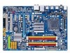
GA-EP43-UD3L/US3L Motherboard Layout GA-EP43-UD3L/US3L PHASE LED FDD KB_MS R_SPDIF COAXIAL R_USB_1 R_USB_2 R_USB_3 ATX_12V LGA775 CPU_FAN PWR_FAN ATX USB_LAN F_AUDIO SYS_FAN1 AUDIO Intel® P43 RTL8111C PCIEX1_1 PCIEX1_2 DDR2_1 DDR2_2 DDR2_3 DDR2_4 SYS_FAN2 PCIEX16 CODEC SPDIF_O CD_IN - Gigabyte GA-EP43-US3L | Manual - Page 8
1 PCI Express x16 LGA775 Processor CPU CLK+/(400(O.C.)/333/266/200 MHz) PCIe CLK (100 MHz) PCI Express x16 PCIe CLK (100 MHz) 4 PCI Express x1 x1 x1 x1 x1 LAN RJ45 RTL 8111C x1 PCI Express Bus ATA-133/100/66/ 33 IDE Channel JMicron 368 Host Interface Intel® P43 DDR2 1200/1066/ 800 - Gigabyte GA-EP43-US3L | Manual - Page 9
's manual and follow these procedures: • Prior to installation, do not remove or break motherboard S/N wrist strap when handling electronic components such as a motherboard, CPU or memory. If you do not have an ESD wrist steps or have a problem related to the use of the product, please consult - Gigabyte GA-EP43-US3L | Manual - Page 10
Product Specifications CPU Front Side Bus Chipset Memory Audio LAN Expansion Slots Storage Interface USB Support for an Intel® CoreTM 2 Extreme processor/ Intel® CoreTM 2 Quad processor/Intel® CoreTM 2 Duo processor/ Intel® Pentium® Dual-Core processor/Intel® Celeron® processor in the LGA 775 - Gigabyte GA-EP43-US3L | Manual - Page 11
iTE IT8718 chip Hardware Monitor System voltage detection CPU/System temperature detection CPU/System/Power fan speed detection CPU overheating warning CPU/System/Power fan fail warning CPU/System fan speed control (Note 2) Only for GA-EP43-UD3L. - 11 - Hardware Installation - Gigabyte GA-EP43-US3L | Manual - Page 12
, the actual memory size displayed will be less than 4 GB. (Note 2) Whether the CPU/System fan speed control function is supported will depend on the CPU/ System cooler you install. (Note 3) Available functions in EasyTune may differ by motherboard model. GA-EP43-UD3L/US3L Motherboard - 12 - - Gigabyte GA-EP43-US3L | Manual - Page 13
do so according to your hardware specifications including the CPU, graphics card, memory, hard drive, etc. 1-3-1 Installing the CPU A. Locate the alignment keys on the motherboard CPU socket and the notches on the CPU. LGA775 CPU Socket Alignment Key LGA 775 CPU Alignment Key Pin One Corner of - Gigabyte GA-EP43-US3L | Manual - Page 14
corner of the CPU socket (or you may align the CPU notches with the socket alignment keys) and gently insert the CPU into position. Step 5: Once the CPU is properly inserted, replace the load plate and push the CPU socket lever back into its locked position. GA-EP43-UD3L/US3L Motherboard - 14 - - Gigabyte GA-EP43-US3L | Manual - Page 15
. Check that the Male and Female push pins are joined closely. (Refer to your CPU cooler installation manual for instructions on installing the cooler.) Step 5: After the installation, check the back of the motherboard. If the push pin is inserted as the picture above, the installation is complete - Gigabyte GA-EP43-US3L | Manual - Page 16
direction. 1-4-1 Dual Channel Memory Configuration This motherboard provides four DDR2 memory sockets and supports Dual Channel Technology. After the memory is installed, the BIOS will automatically detect the specifications and capacity of the memory. Enabling Dual Channel memory mode will double - Gigabyte GA-EP43-US3L | Manual - Page 17
. DDR2 DIMMs are not compatible to DDR DIMMs. Be sure to install DDR2 DIMMs on this motherboard. Notch DDR2 DIMM A DDR2 memory module has a notch, so it can only fit in one direction. Follow the steps below to correctly install your memory modules in the memory sockets. Step 1: Note the orientation - Gigabyte GA-EP43-US3L | Manual - Page 18
expansion card: • Make sure the motherboard supports the expansion card. Carefully read the manual that came with your expansion card. necessary, go to BIOS Setup to make any required BIOS changes for your expansion card(s). 7. Install the driver provided with the GA-EP43-UD3L/US3L Motherboard - 18 - - Gigabyte GA-EP43-US3L | Manual - Page 19
, first remove the cable from your device and then remove it from the motherboard. • When removing the cable, pull it straight out from the connector. Do not rock it side to side to prevent an electrical short inside the cable connector. Only for GA-EP43-UD3L. - 19 - Hardware Installation - Gigabyte GA-EP43-US3L | Manual - Page 20
different functions via the audio software. Only microphones still MUST be connected to the default Mic in jack ( ). Refer to the instructions on setting up a 2/4/5.1/ 7.1-channel audio configuration in Chapter 5, "Configuring 2/4/5.1/7.1-Channel Audio." GA-EP43-UD3L/US3L Motherboard - 20 - - Gigabyte GA-EP43-US3L | Manual - Page 21
ATX 3) CPU_FAN 4) SYS_FAN1/SYS_FAN2 5) PWR_FAN 6) FDD 7) IDE 8) SATA2_0/1/2/3/4/5 9) PWR_LED 10) F_AUDIO 11) F_PANEL 12) CD_IN 13) SPDIF_I 14) SPDIF_O 15) F_USB1/F_USB2 16) LPT 17) COMA 18) CI 19) CLR_CMOS 20) BATTERY 21) PHASE LED to the connector on the motherboard. - 21 - Hardware Installation - Gigabyte GA-EP43-US3L | Manual - Page 22
12V power connector mainly supplies power to the CPU. If the 12V power connector is not compatible with power supplies with 2x10 power connectors. When using a 2x12 power supply, remove the protective cover from the main power connector on the motherboard ATX) GA-EP43-UD3L/US3L Motherboard - 22 - - Gigabyte GA-EP43-US3L | Manual - Page 23
wire is the ground wire). The motherboard supports CPU fan speed control, which requires the use of a CPU fan with fan speed control design your CPU and system from overheating. Overheating may result in damage to the CPU or the system may hang. • These fan headers are not configuration jumper - Gigabyte GA-EP43-US3L | Manual - Page 24
3Gb/s standard and are compatible with SATA 1.5Gb/s standard. Each SATA connector supports a single SATA device. 7 SATA2_3 SATA2_4 SATA2_5 7 17 17 1 SATA2_0 SATA2_1 SATA2_2 1 Pin No. 1 2 3 4 5 6 7 Definition GND TXP TXN GND RXN RXP GND GA-EP43-UD3L/US3L Motherboard - 24 - Please connect the - Gigabyte GA-EP43-US3L | Manual - Page 25
• The front panel audio header supports HD audio by default. If your chassis provides an AC'97 front panel audio module, refer to the instructions on how to activate AC'97 functioninality via the audio software in Chapter 5, "Configuring 2/4/5.1/7.1-Channel Audio." • Audio signals will be present - Gigabyte GA-EP43-US3L | Manual - Page 26
a beep code. One single short beep will be heard if no problem is detected at system startup. If a problem is detected, the BIOS may issue beeps in different patterns to indicate the problem. Refer to Chapter 5, "Troubleshooting," for information about beep codes. • HD (Hard Drive Activity LED, Blue - Gigabyte GA-EP43-US3L | Manual - Page 27
the header. Pin No. Definition 1 CD-L 2 GND 3 GND 4 CD-R 1 13) SPDIF_I (S/PDIF In Header) This header supports digital S/PDIF in and can connect to an audio device that supports digital audio out via an optional S/PDIF in cable. For purchasing the optional S/PDIF in cable, please contact - Gigabyte GA-EP43-US3L | Manual - Page 28
PDIF digital audio cable, carefully read the manual for your expansion card. Pin No. Definition 1 SPDIFO 1 2 GND 15) F_USB1/F_USB2 (USB Headers) The headers conform to USB 2.0/1.1 specification. Each the power outlet to prevent damage to the USB bracket. GA-EP43-UD3L/US3L Motherboard - 28 - - Gigabyte GA-EP43-US3L | Manual - Page 29
16) LPT (Parallel Port Header) The LPT header can provide one parallel port via an optional LPT port cable. For purchasing the optional LPT port cable, please contact the local dealer. 25 1 26 Pin No. 1 2 3 4 5 6 7 8 9 10 11 12 13 2 Definition STBAFDPD0 ERRPD1 INITPD2 SLINPD3 GND PD4 GND PD5 - Gigabyte GA-EP43-US3L | Manual - Page 30
jumper. Failure to do so may cause damage to the motherboard. • After system restart, go to BIOS Setup to load factory defaults (select Load Optimized Defaults) or manually configure the BIOS settings (refer to Chapter 2, "BIOS Setup," for BIOS configurations). GA-EP43-UD3L/US3L Motherboard - 30 - - Gigabyte GA-EP43-US3L | Manual - Page 31
The battery provides power to keep the values (such as BIOS configurations, date, and time information) in the CMOS when the computer 21) PHASE LED The number of lighted LEDs indicates the CPU loading. The higher the CPU loading, the more the number of lighted LEDs. To enable the Phase LED display - Gigabyte GA-EP43-US3L | Manual - Page 32
GA-EP43-UD3L/US3L Motherboard - 32 - - Gigabyte GA-EP43-US3L | Manual - Page 33
that searches and downloads the latest version of BIOS from the Internet and updates the BIOS. For instructions on using the Q-Flash and @BIOS utilities, refer to Chapter 4, "BIOS Update Utilities." • Because BIOS flashing is potentially risky, if you do not encounter problems using the current - Gigabyte GA-EP43-US3L | Manual - Page 34
boot order will still be based on BIOS Setup settings. You can access Boot Menu again to change the first boot device setting as needed. : Q-FLASH Press the key to access the Q-Flash utility directly without having to enter BIOS Setup first. GA-EP43-UD3L/US3L Motherboard - 34 - - Gigabyte GA-EP43-US3L | Manual - Page 35
enter a sub-menu. (Sample BIOS Version: GA-EP43-UD3L E3c) CMOS Setup Utility-Copyright (C) 1984-2008 Award Software MB Intelligent Tweaker(M.I.T.) Standard CMOS Features Advanced BIOS Features Integrated Peripherals Power Management Setup PnP/PCI Configurations PC Health Status Load - Gigabyte GA-EP43-US3L | Manual - Page 36
and exit BIOS Setup. (Pressing can also carry out this task.) Exit Without Saving Abandon all changes and the previous settings remain in effect. Pressing to the confirmation message will exit BIOS Setup. (Pressing can also carry out this task.) GA-EP43-UD3L/US3L Motherboard - 36 - Gigabyte GA-EP43-US3L | Manual - Page 37
+/-/PU/PD: Value F10: Save F6: Fail-Safe Defaults ESC: Exit F1: General Help F7: Optimized Defaults (Note 1) This item appears only if you install a CPU that supports this feature. (Note 2) This item appears only if you install a memory module that supports this feature. - 37 - BIOS Setup - Gigabyte GA-EP43-US3L | Manual - Page 38
fails to boot after overclocking, please wait for 20 seconds to allow for automated system reboot, or clear the CMOS values to reset the board to default values. (Default: Disabled) (Note) This item appears only if you install a CPU that supports this feature. GA-EP43-UD3L/US3L Motherboard - 38 - - Gigabyte GA-EP43-US3L | Manual - Page 39
, set this item to 266 MHz. For a 1333 MHz FSB CPU, set this item to 333 MHz. Important It is highly recommended that the CPU frequency be set in accordance with the CPU specifications. PCI Express Frequency (Mhz) Allows you to manually set the PCIe clock frequency. The adjustable range is from - Gigabyte GA-EP43-US3L | Manual - Page 40
) and System Memory Multiplier settings. DRAM Timing Selectable (SPD) Manual allows all DRAM Timing items below to be configurable. Options are: Auto (default), Manual. (Note) This item appears only if you install a memory module that supports this feature. GA-EP43-UD3L/US3L Motherboard - 40 - - Gigabyte GA-EP43-US3L | Manual - Page 41
: Auto (default), 1~255. tRTP Options are: Auto (default), 1~15. Command Rate(CMD) Options are: Auto (default), 1~3. ******** ESC: Exit F1: General Help F7: Optimized Defaults - 41 - BIOS Setup - Gigabyte GA-EP43-US3L | Manual - Page 42
Control Options are: Auto (default), +800ps~-700ps. DIMM2 Clock Skew Control Options are: Auto (default), +800ps~-700ps. ESC: Exit F1: General Help F7: Optimized Defaults GA-EP43-UD3L/US3L Motherboard - 42 - - Gigabyte GA-EP43-US3L | Manual - Page 43
you to determine whether to fine-tune memory parameters to enhance memory compatibility. Auto Lets the BIOS decide whether to enable this function. (Default) Disabled Disables this function. Enabled Enables this function to enhance memory compatibility. Channel A/B Driving Settings CMOS Setup - Gigabyte GA-EP43-US3L | Manual - Page 44
Board Voltage Control >>> CPU CPU Vcore The default is Auto. CPU Termination The default is Auto. CPU Reference The default is Auto. >>> MCH/ICH MCH Core The default is Auto. ICH I/O The default is Auto. >>> DRAM DRAM Voltage The default is Auto. ******** GA-EP43-UD3L/US3L Motherboard - 44 - - Gigabyte GA-EP43-US3L | Manual - Page 45
A Floppy 3 Mode Support [1.44M, 3.5"] [Disabled] Halt On [All, But Keyboard] Base Memory Extended Memory 640K 510M Move Enter: General Help F7: Optimized Defaults Total Memory CMOS Setup Utility-Copyright (C) 1984-2007 Configure your IDE/SATA devices by using one of the three methods below: - Gigabyte GA-EP43-US3L | Manual - Page 46
are determined by the BIOS POST. Base Memory Also called conventional memory. Typically, 640 KB will be reserved for the MS-DOS operating system. Extended Memory The amount of extended memory. Total Memory The total amount of memory installed on the system. GA-EP43-UD3L/US3L Motherboard - 46 - - Gigabyte GA-EP43-US3L | Manual - Page 47
BIOS Features Hard Disk Boot Priority First Boot Device Second Boot Device Third Boot Device Password Check HDD S.M.A.R.T. Capability CPU Multi-Threading (Note) Limit CPUID Max. to 3 (Note) No-Execute Memory Protect (Note) CPU Enhanced Halt (C1E) (Note) C2/C2E State Support on the list. Press < - Gigabyte GA-EP43-US3L | Manual - Page 48
(Default: Disabled) No-Execute Memory Protect (Note) Enables or disables Intel® Execute Disable Bit function. This function may enhance a CPU that supports this feature. For more information about Intel CPUs' unique features, please visit Intel's website. GA-EP43-UD3L/US3L Motherboard - 48 - Gigabyte GA-EP43-US3L | Manual - Page 49
Allows you to set a delay time for the BIOS to initialize the hard drive as the system boots up. The adjustable range is from 0 to 15 seconds. (Default: 0) Full Screen LOGO Show Allows you to determine whether to display the GIGABYTE Logo at system startup. Disabled displays normal POST message - Gigabyte GA-EP43-US3L | Manual - Page 50
enabed, the system will dynamically detects if LAN cable(s) is connected or not. If not, the corresponding LAN controller will be disabled automatically. (Default: Disabled) GA-EP43-UD3L/US3L Motherboard - 50 - - Gigabyte GA-EP43-US3L | Manual - Page 51
LAN Cable Is Attached... If no LAN cable is attached to the motherboard, the Status fields of all four pairs of wires will show Open or when the LAN Boot ROM is activated. When a Cable Problem Occurs... If a cable problem occurs on a specified pair of wires, the Status field will 51 - BIOS Setup - Gigabyte GA-EP43-US3L | Manual - Page 52
. (Default: Disabled) USB Storage Function Determines whether to detect USB storage devices, including USB flash drives and USB hard drives during the POST. (Default: Enabled) GA-EP43-UD3L/US3L Motherboard - 52 - - Gigabyte GA-EP43-US3L | Manual - Page 53
Support (Note) HPET Mode ( Support [S3(STR)] [Instant-Off] [Enabled] [Enabled] [Disabled] Everyday 0 : 0 : 0 [Enabled] [32-bit to RAM) sleep Configures need an ATX power supply supports wake-up function. (Default: Enabled) (Note) Supported on Windows® Vista® operating system only. - - Gigabyte GA-EP43-US3L | Manual - Page 54
Enabled, the following four functions will become unavailable: PME event wake up, power on by mouse, power on by keyboard, and wake on LAN. (Note) Supported on Windows® Vista® operating system only. GA-EP43-UD3L/US3L Motherboard - 54 - - Gigabyte GA-EP43-US3L | Manual - Page 55
Utility-Copyright (C) 1984-2008 Award Software PnP/PCI Configurations PCI1 IRQ Assignment PCI2 IRQ Assignment [Auto] [Auto : Fail-Safe Defaults ESC: Exit F1: General Help F7: Optimized Defaults BIOS auto-assigns IRQ to the first PCI slot. (Default) Assigns IRQ 3,4,5,7,9,10,11,12,14, - Gigabyte GA-EP43-US3L | Manual - Page 56
), 60oC/140oF, 70oC/158oF, 80oC/ 176oF, 90oC/194oF. CPU/SYSTEM/POWER FAN Fail Warning Allows the system to emit warning sound if the CPU/system/power fan is not connected or fails. Check the fan condition or fan connection when this occurs. (Default: Disabled) GA-EP43-UD3L/US3L Motherboard - 56 - - Gigabyte GA-EP43-US3L | Manual - Page 57
pin CPU fan. PWM Sets PWM mode for a 4-pin CPU fan. Note: The Voltage mode can be set for a 3-pin CPU fan or a 4-pin CPU fan. However, for a 4-pin CPU fan that is not designed following Intel PWM fan specifications, selecting PWM mode may not effectively reduce the fan speed. - 57 - BIOS Setup - Gigabyte GA-EP43-US3L | Manual - Page 58
/eN&)?ENxit Setup PnP/PCI Configurations Exit Without Saving PC Health BIOS default settings. The BIOS defaults settings helps the system to operate in optimum state. Always load the Optimized defaults after updating the BIOS or after clearing the CMOS values. GA-EP43-UD3L/US3L Motherboard - Gigabyte GA-EP43-US3L | Manual - Page 59
-Copyright (C) 1984-2008 Award Software MB Intelligent Tweaker(M.I.T.) Standard CMOS Features Advanced BIOS Features Integrated Peripherals Power Management SEentutepr Password: PnP/PCI Configurations PC Health Status Load Fail-Safe Defaults Load Optimized Defaults Set Supervisor - Gigabyte GA-EP43-US3L | Manual - Page 60
/PCI Configurations Exit BIOS F12: Load CMOS from BIOS Abandon all Data Press on this item and press the key. This exits the BIOS Setup without saving the changes made in BIOS Setup to the CMOS. Press or to return to the BIOS Setup Main Menu. GA-EP43-UD3L/US3L Motherboard - Gigabyte GA-EP43-US3L | Manual - Page 61
other drivers. • After the drivers are installed, follow the onscreen instructions to restart your system. You can install other applications included in the motherboard driver disk. • For USB 2.0 driver support under the Windows XP operating system, please install the Windows XP Service Pack - Gigabyte GA-EP43-US3L | Manual - Page 62
that GIGABYTE develops and some free software. You can click the Install button on the right of an item to install it. 3-3 Technical Manuals This page provides GIGABYTE's application guides, content descriptions for this driver disk, and the motherboard manuals. GA-EP43-UD3L/US3L Motherboard - 62 - Gigabyte GA-EP43-US3L | Manual - Page 63
3-4 Contact For the detailed contact information of the GIGABYTE Taiwan headquarter or worldwide branch offices, click the URL on this page to link to the GIGABYTE Website. 3-5 System This page provides the basic system information. - 63 - Drivers Installation - Gigabyte GA-EP43-US3L | Manual - Page 64
3-6 Download Center To update the BIOS, drivers, or applications, click the Download Center button to link to the GIGABYTE Web site. The latest version of the BIOS, drivers, or applications will be displayed. GA-EP43-UD3L/US3L Motherboard - 64 - - Gigabyte GA-EP43-US3L | Manual - Page 65
and drivers are installed. • The amount of data and hard drive access speed may affect the speed at which the data is backed up/restored. • It takes longer to back up a hard drive than to restore it. System Requirements: • Intel® platform • At least 512 MB of system memory • VESA compatible graphics - Gigabyte GA-EP43-US3L | Manual - Page 66
Recovery2 cannot save the backup file. B. Accessing Xpress Recovery2 1. Boot from the motherboard driver disk to access Xpress Recovery2 for the first time. When you see the following message When finished, go to Disk Management to check disk allocation. GA-EP43-UD3L/US3L Motherboard - 66 - - Gigabyte GA-EP43-US3L | Manual - Page 67
D. Using the Restore Function in Xpress Recovery2 Select RESTORE to restore the backup to your hard drive in case the system breaks down. The RESTORE option will not be present if no backup is created before. E. Removing the Backup Step 1: If you wish to remove the backup file, select REMOVE. F. - Gigabyte GA-EP43-US3L | Manual - Page 68
, Inc. EP43-UD3L E3c . . . . : BIOS Setup : XpressRecovery2 : Boot Menu : Qflash 11/27/2008-P43-ICH10-7A69PG0FC-00 Because BIOS flashing is potentially risky, please do it with caution. Inadequate BIOS flashing may result in system malfunction. GA-EP43-UD3L/US3L Motherboard - 68 - Gigabyte GA-EP43-US3L | Manual - Page 69
arrow key to select Update BIOS from Drive and press . • The Save Main BIOS to Drive option allows you to save the current BIOS file. • Q-Flash only supports USB flash drive or hard drives using FAT32/16/12 file system. • If the BIOS update file is saved to a hard drive in RAID/AHCI mode or - Gigabyte GA-EP43-US3L | Manual - Page 70
F11: Save CMOS to BIOS F12: Load CMOS from BIOS Load Optimized Defaults Press to load BIOS defaults Step 6: Select Save & Exit Setup and then press to save settings to CMOS and exit BIOS Setup. The procedure is complete after the system restarts. GA-EP43-UD3L/US3L Motherboard - 70 - - Gigabyte GA-EP43-US3L | Manual - Page 71
. If the BIOS update file for your motherboard is not present on the @BIOS server site, please manually download the BIOS update file from GIGABYTE's website and follow the instructions in "Update the BIOS without Using the Internet Update Function" below. 2. Update the BIOS without Using the - Gigabyte GA-EP43-US3L | Manual - Page 72
hardware components such as CPU, chipset, and memory and reduce the useful life of these components. Before you do the overclock/overvoltage, make sure that you fully know each function of EasyTune 6, or system instability or other unexpected results may occur. GA-EP43-UD3L/US3L Motherboard - 72 - - Gigabyte GA-EP43-US3L | Manual - Page 73
Mode, GIGABYTE Dynamic Energy Saver Advanced shows how much power they have saved in a set period of time. Meter Mode - Button Information Table Button Description 1 Dynamic Energy Saver On/Off Switch (Default: Off) 2 Motherboard Phase LED On/Off Switch (Default: On) 3 Dynamic CPU Frequency - Gigabyte GA-EP43-US3L | Manual - Page 74
Motherboard Phase LED On/Off Switch (Default: On) 3 Dynamic CPU Frequency Function On/Off Switch (Default: Off) 4 CPU Throttling Display 5 3-Level CPU Voltage Switch (Default:1) (Note 3) 6 CPU Voltage Display 7 Dynamic Power Phase Status 8 Current CPU GA-EP43-UD3L/US3L Motherboard - 74 - - Gigabyte GA-EP43-US3L | Manual - Page 75
motherboard driver disk, go to Start>All Programs>GIGABYTE> Q-Share.exe to launch the Q-Share tool. Find the Q-Share icon in your system tray and right-click on this icon to configure folder Changes the data folder to be shared (Note) Updates Q-Share online Displays the current Q-Share version Exits - Gigabyte GA-EP43-US3L | Manual - Page 76
over 300 MB of available space. • Each storage volume can accommodate 64 shadow copies. When this limit is reached, the oldest shadow copy will be deleted and unable to be restored. Shadow copies are read-only so you cannot edit the contents of a shadow copy. GA-EP43-UD3L/US3L Motherboard - 76 - - Gigabyte GA-EP43-US3L | Manual - Page 77
jack and manually configure the jack for microphone functionality. • Audio signals will be present on both of the front and back panel audio connections simultaneously. If you want to mute the back panel audio (only supported when using an HD front panel audio module), refer to instructions on the - Gigabyte GA-EP43-US3L | Manual - Page 78
For HD Audio Only): Click Device advanced settings on the top right corner on the Speaker Configuration tab to open the Device advanced settings dialog box. Select the Mute the rear output device, when a front headphone plugged in check box. Click OK to complete. GA-EP43-UD3L/US3L Motherboard - 78 - Gigabyte GA-EP43-US3L | Manual - Page 79
: Step 1: First, attach the connector at the end of the cable to the SPDIF_I header on your motherboard. Step 2: Secure the metal bracket to the chassis back panel with a screw. 2. Configuring S/PDIF In: On the Digital Input screen, click the Default Format tab to select the default format. Click - Gigabyte GA-EP43-US3L | Manual - Page 80
PDIF optical cable (either one) to an external decoder for transmitting the S/PDIF digital audio signals. 2. Configuring S/PDIF Out: On the Digital Output screen, click the Default Format tab and then select the sample rate and bit depth. Click OK to complete. GA-EP43-UD3L/US3L Motherboard - 80 - - Gigabyte GA-EP43-US3L | Manual - Page 81
installing the audio driver, the HD Audio Manager icon will appear in the notification area. Doubleclick the icon to access the HD Audio Manager. Step 2: Connect your microphone to the Mic in jack (pink) on the back panel or the Mic in jack (pink) on the front panel. Then configure the jack for - Gigabyte GA-EP43-US3L | Manual - Page 82
, and then click Sound Recorder to begin the sound recording. * Enabling Stereo Mix If the HD Audio Manager does not display the recording device you wish to use, refer to the steps below. The right-click on an empty space and select Show Disabled Devices. GA-EP43-UD3L/US3L Motherboard - 82 - - Gigabyte GA-EP43-US3L | Manual - Page 83
Step 4: Now you can access the HD Audio Manager to configure Stereo Mix and use Sound Recorder to record audio file upon completion (by default, the recorded audio is saved as a WMA file). B. Playing the Recorded Sound: You can play your recording in a digital media player program that supports - Gigabyte GA-EP43-US3L | Manual - Page 84
error 1 long, 1 short: Memory or motherboard error 1 long, 2 short: Monitor or graphics card error 1 long, 3 short: Keyboard error 1 long, 9 short: BIOS ROM error Continuous long beeps: Graphics card not inserted properly Continuous short beeps: Power error GA-EP43-UD3L/US3L Motherboard - 84 - - Gigabyte GA-EP43-US3L | Manual - Page 85
and solved. Secure the CPU No cooler on the CPU. Connect the CPU cooler power cable to the motherboard. The problem is verified and solved. No Correctly insert the memory into the memory socket. The problem is verified and solved. Press to enter BIOS Setup. Select "Load Fail - Gigabyte GA-EP43-US3L | Manual - Page 86
. END If the procedure above is unable to solve your problem, contact the place of purchase or local dealer for help. Or go to the Support\Technical Service Zone page to submit your question. Our customer service staff will reply you as soon as possible. GA-EP43-UD3L/US3L Motherboard - 86 - - Gigabyte GA-EP43-US3L | Manual - Page 87
GIGABYTE. Our Commitment to Preserving the Environment In addition to high-efficiency performance, all GIGABYTE motherboards office, your household waste disposal service or where you purchased the Customer Care number listed in your product's user's manual and we will be glad to help you - Gigabyte GA-EP43-US3L | Manual - Page 88
disposed of properly. China Restriction of Hazardous Substances Table The following table is supplied in compliance with China's Restriction of Hazardous Substances (China RoHS) requirements: GA-EP43-UD3L/US3L Motherboard - 88 - - Gigabyte GA-EP43-US3L | Manual - Page 89
- 89 - Appendix - Gigabyte GA-EP43-US3L | Manual - Page 90
GA-EP43-UD3L/US3L Motherboard - 90 - - Gigabyte GA-EP43-US3L | Manual - Page 91
- 91 - Appendix - Gigabyte GA-EP43-US3L | Manual - Page 92
GA-EP43-UD3L/US3L Motherboard - 92 - - Gigabyte GA-EP43-US3L | Manual - Page 93
- 93 - Appendix - Gigabyte GA-EP43-US3L | Manual - Page 94
GA-EP43-UD3L/US3L Motherboard - 94 - - Gigabyte GA-EP43-US3L | Manual - Page 95
231, Taiwan TEL: +886-2-8912-4000 FAX: +886-2-8912-4003 Tech. and Non-Tech. Support (Sales/Marketing) : http://ggts.gigabyte.com.tw WEB address (English): http://www.gigabyte.com.tw WEB address (Chinese): http://www.gigabyte.tw G.B.T. INC. - U.S.A. TEL: +1-626-854-9338 FAX: +1-626-854-9339 Tech - Gigabyte GA-EP43-US3L | Manual - Page 96
in the language list on the top right corner of the website. GIGABYTE Global Service System To submit a technical or non-technical (Sales/ Marketing) question, please link to : http://ggts.gigabyte.com.tw Then select your language to enter the system. GA-EP43-UD3L/US3L Motherboard - 96 -
-
 1
1 -
 2
2 -
 3
3 -
 4
4 -
 5
5 -
 6
6 -
 7
7 -
8
-
9
-
10
-
11
-
12
-
13
-
14
-
15
-
16
-
17
-
18
-
19
-
20
-
21
-
22
-
23
-
24
-
25
-
26
-
27
-
28
-
29
-
30
-
31
-
32
-
33
-
34
-
35
-
36
-
37
-
38
-
39
-
40
-
41
-
42
-
43
-
44
-
45
-
46
-
47
-
48
-
49
-
50
-
51
-
52
-
53
-
54
-
55
-
56
-
57
-
58
-
59
-
60
-
61
-
62
-
63
-
64
-
65
-
66
-
67
-
68
-
69
-
70
-
71
-
72
-
73
-
74
-
75
-
76
-
77
-
78
-
79
-
80
-
81
-
82
-
83
-
84
-
85
-
86
-
87
-
88
-
89
-
90
-
91
-
92
-
93
-
94
-
95
-
96
 |
 |

GA-EP43-UD3L/
GA-EP43-US3L
LGA775 socket motherboard for Intel
®
Core
TM
processor family/
Intel
®
Pentium
®
processor family/Intel
®
Celeron
®
processor family
User's Manual
Rev. 1201
12ME-EP43UD3L-1201R