Gigabyte GA-EP45-DS5 Manual
Gigabyte GA-EP45-DS5 Manual
 |
View all Gigabyte GA-EP45-DS5 manuals
Add to My Manuals
Save this manual to your list of manuals |
Gigabyte GA-EP45-DS5 manual content summary:
- Gigabyte GA-EP45-DS5 | Manual - Page 1
GA-EP45-DS5 LGA775 socket motherboard for Intel® CoreTM processor family/ Intel® Pentium® processor family/Intel® Celeron® processor family User's Manual Rev. 1004 12ME-EP45DS5-1004R - Gigabyte GA-EP45-DS5 | Manual - Page 2
Motherboard GA-EP45-DS5 May 15, 2008 Motherboard GA-EP45-DS5 May 15, 2008 - Gigabyte GA-EP45-DS5 | Manual - Page 3
with the product. „ For detailed product information, carefully read the User's Manual. „ For instructions on how to use GIGABYTE's unique features, read or download the information on/from the Support\Motherboard\Technology Guide page on our website. For product-related information, check on our - Gigabyte GA-EP45-DS5 | Manual - Page 4
Table of Contents Box Contents ...6 OptionalItems ...6 GA-EP45-DS5 Motherboard Layout 7 Block Diagram ...8 Chapter 1 Hardware Installation 9 1-6 Installing the SATA Bracket 19 1-7 Back Panel Connectors 20 1-8 Onboard LEDs and Switches 22 1-9 Internal Connectors 23 Chapter 2 BIOS Setup 35 2-1 - Gigabyte GA-EP45-DS5 | Manual - Page 5
Chipset Drivers 65 3-2 Application Software 66 3-3 Technical Manuals 66 3-4 Contact ...67 3-5 System ...67 3-6 Download Center 68 Chapter 4 Unique Features 69 4-1 Xpress Recovery2 69 4-2 BIOS Update Utilities 74 4-2-1 Updating the BIOS with the Q-Flash Utility 74 4-2-2 Updating the BIOS - Gigabyte GA-EP45-DS5 | Manual - Page 6
Box Contents GA-EP45-DS5 motherboard Motherboard driver disk User's Manual Quick Installation Guide One IDE cable and one floppy disk drive cable Four SATA 3Gb/s cables One SATA bracket I/O Shield • The box contents above are for reference only and the actual items shall depend on product package - Gigabyte GA-EP45-DS5 | Manual - Page 7
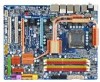
PHASE LED ACPI_LED (S0/1/3/4/5_LED) PWR_FAN GA-EP45-DS5 Motherboard Layout KB_MS CPU_LED R_SPDIF USB_1394_1 ATX_12V_2X LGA775 CPU_FAN USB_1394_2 DIMM_LED USB_LAN2 ATX USB_LAN1 RTL8111C F_AUDIO AUDIO BAT PCIEX1_1 PE1_LED GD1 GD2 RTL8111C PCIEX1_2 PCIEX16 Intel® P45 PE_LED DDR2_1 - Gigabyte GA-EP45-DS5 | Manual - Page 8
3Gb/s 2 SATA 3Gb/s SiI5723 GIGABYTE SiI5723 SATA2 ATA-133/100/66/33 IDE Channel PCI Bus TSB43AB23 3 IEEE 1394a Host Interface DDR2 1200/1066/800/667 MHz Intel® P45 Dual Channel Memory MCH CLK (400/333/266/200 MHz) Intel® ICH10R Dual BIOS 6 SATA 3Gb/s 12 USB Ports LPC Bus IT8720 Floppy - Gigabyte GA-EP45-DS5 | Manual - Page 9
, carefully read the user's manual and follow these procedures: • Prior to installation, do not remove or break motherboard S/N (Serial Number) sticker or you are uncertain about any installation steps or have a problem related to the use of the product, please consult a certified computer technician. - Gigabyte GA-EP45-DS5 | Manual - Page 10
chips (Smart Backup): - 4 x SATA 3Gb/s connectors (GS0-Source, GS1, GS2-Source, GS3) supporting up to 4 SATA 3Gb/s devices (Note 4) - Support for Smart Backup (RAID 1) (Note 5) Š iTE IT8720 chip: - 1 x floppy disk drive connector supporting up to 1 floppy disk drive GA-EP45-DS5 Motherboard - 10 - - Gigabyte GA-EP45-DS5 | Manual - Page 11
connector Š 1 x floppy disk drive connector Š 1 x IDE connector Š 10 x SATA 3Gb/s connectors Š 1 x CPU fan header Š 2 x system fan headers Š Š 1 x serial port header Š 1 x chassis intrusion header Š 1 x power LED header Š 1 x power switch Š 1 x reset switch Š 1 x clearing CMOS switch - Gigabyte GA-EP45-DS5 | Manual - Page 12
.) (Note 6) Whether the CPU/system fan speed control function is supported will depend on the CPU/ system cooler you install. (Note 7) Available functions in EasyTune may differ by motherboard model. (Note 8) This feature is optional due to different regional policy. GA-EP45-DS5 Motherboard - 12 - - Gigabyte GA-EP45-DS5 | Manual - Page 13
CPU and CPU Cooler Read the following guidelines before you begin to install the CPU: • Make sure that the motherboard supports the CPU. (Go to GIGABYTE's website for the latest CPU support list.) • Always turn off the computer and unplug the power cord from the power outlet before installing the - Gigabyte GA-EP45-DS5 | Manual - Page 14
B. Follow the steps below to correctly install the CPU into the motherboard CPU socket. Before installing the CPU, make sure to turn off the computer and unplug the properly inserted, replace the load plate and push the CPU socket lever back into its locked position. GA-EP45-DS5 Motherboard - 14 - - Gigabyte GA-EP45-DS5 | Manual - Page 15
CPU cooler installation manual for instructions on installing the cooler.) Step 5: After the installation, check the back of the motherboard. If the push CPU cooler to the CPU fan header (CPU_FAN) on the motherboard. Use extreme care when removing the CPU cooler because the thermal grease/tape - Gigabyte GA-EP45-DS5 | Manual - Page 16
motherboard supports the memory. It is recommended that memory of the same capacity, brand, speed, and chips be used. (Go to GIGABYTE's website for the latest memory support ) DDR2_1 DDR2_2 DDR2_3 DDR2_4 Due to chipset limitation, read the following guidelines before GA-EP45-DS5 Motherboard - 16 - - Gigabyte GA-EP45-DS5 | Manual - Page 17
power outlet to prevent damage to the memory module. DDR2 DIMMs are not compatible to DDR DIMMs. Be sure to install DDR2 DIMMs on this motherboard. Notch DDR2 DIMM A DDR2 memory module has a notch, so it can only fit in one direction. Follow the steps below to correctly install your memory - Gigabyte GA-EP45-DS5 | Manual - Page 18
Make sure the motherboard supports the expansion card. Carefully read the manual that came with BIOS Setup to make any required BIOS changes for your expansion card(s). 7. Install the driver then lift the card straight out from the slot. GA-EP45-DS5 Motherboard - 18 - • Removing the Card from the - Gigabyte GA-EP45-DS5 | Manual - Page 19
cable. Follow the steps below to install the SATA bracket: Step 1: Locate one free PCI slot and secure the SATA bracket to the chassis back panel with a screw. Step 2: Connect the SATA cable from the bracket to the SATA port on your motherboard. Step 3: Step 4: Connect the power Plug one end - Gigabyte GA-EP45-DS5 | Manual - Page 20
The USB port supports the USB LEDs. Connection/ Speed LED Activity LED LAN Port Connection/Speed LED motherboard. • When removing the cable, pull it straight out from the connector. Do not rock it side to side to prevent an electrical short inside the cable connector. GA-EP45-DS5 Motherboard - Gigabyte GA-EP45-DS5 | Manual - Page 21
to perform different functions via the audio software. Only microphones still MUST be connected to the default Mic in jack ( ). Refer to the instructions on setting up a 2/4/5.1/ 7.1-channel audio configuration in Chapter 5, "Configuring 2/4/5.1/7.1-Channel Audio." - 21 - Hardware Installation - Gigabyte GA-EP45-DS5 | Manual - Page 22
LEDs This motherboard has 7 onboard LEDs controlled by the system BIOS. The 7 LEDs indicate if a component (including CPU and memory) or a device (including PCI and PCIe cards and IDE/SATA devices) works abnormally. The LED will light up during the POST when the components/devices have a problem - Gigabyte GA-EP45-DS5 | Manual - Page 23
) F1_1394 17) F_USB1 / F_USB2 18) COMA 19) CLR_CMOS 20) CI 21) BAT 22) PHASE LED Read the following guidelines before connecting external devices: • First make sure your devices are compliant with the been securely attached to the connector on the motherboard. - 23 - Hardware Installation - Gigabyte GA-EP45-DS5 | Manual - Page 24
is recommended by the CPU manufacturer when using an Intel Extreme Edition CPU (130W). • To meet expansion requirements, it pin 12V) 6 +12V (Only for 2x4 pin 12V) 7 +12V 8 +12V 12 24 1 13 ATX GA-EP45-DS5 Motherboard ATX: Pin No. 1 2 3 4 5 6 7 8 9 10 11 12 Definition Pin No. 3.3V - Gigabyte GA-EP45-DS5 | Manual - Page 25
design. When connecting a fan cable, be sure to connect it in the correct orientation (the black connector wire is the ground wire). The motherboard supports CPU fan speed control, which requires the use of a CPU fan with fan speed control design. For optimum heat dissipation, it is recommended - Gigabyte GA-EP45-DS5 | Manual - Page 26
be an even number.) • A RAID 10 configuration requires at least four hard drives and the total number of hard drives must be an even number. GA-EP45-DS5 Motherboard - 26 - - Gigabyte GA-EP45-DS5 | Manual - Page 27
-Source/GS3 (SATA 3Gb/s Connectors, Controlled by GIGABYTE SATA2/SiI5723, Purple) The SATA connectors conform to SATA 3Gb/s standard and are compatible with SATA 1.5Gb/s standard. Each SATA connector supports a single SATA device. The GIGABYTE SATA2/SiI5723 controllers support Smart Backup Function - Gigabyte GA-EP45-DS5 | Manual - Page 28
. A front panel module mainly consists of power switch, reset switch, power LED, hard drive activity LED, speaker and etc. When connecting your chassis front panel module to this header, make sure the wire assignments and the pin assignments are matched correctly. GA-EP45-DS5 Motherboard - 28 - - Gigabyte GA-EP45-DS5 | Manual - Page 29
the motherboard header. Incorrect connection between the module connector and the motherboard header will make the device unable to work or even panel audio header supports HD audio by default. If your chassis provides an AC'97 front panel audio module, refer to the instructions on how to - Gigabyte GA-EP45-DS5 | Manual - Page 30
This header supports digital S/PDIF out and connects a S/PDIF digital audio cable (provided by expansion cards) for digital audio output from your motherboard to certain , carefully read the manual for your expansion card. Pin No. Definition 1 1 SPDIFO 2 GND GA-EP45-DS5 Motherboard - 30 - - Gigabyte GA-EP45-DS5 | Manual - Page 31
16) F1_1394 (IEEE 1394a Header, Gray) The header conforms to IEEE 1394a specification. The IEEE 1394a header can provide one IEEE 1394a port via an optional IEEE 1394a bracket. For purchasing the optional IEEE 1394a bracket, please contact the local dealer. Pin No. Definition 9 1 1 TPA+ 2 - Gigabyte GA-EP45-DS5 | Manual - Page 32
the jumper. Failure to do so may cause damage to the motherboard. • After system restart, go to BIOS Setup to load factory defaults (select Load Optimized Defaults) or manually configure the BIOS settings (refer to Chapter 2, "BIOS Setup," for BIOS configurations). GA-EP45-DS5 Motherboard - 32 - - Gigabyte GA-EP45-DS5 | Manual - Page 33
This motherboard provides a chassis detection feature that detects if the chassis cover has been removed. This function requires a chassis with chassis intrusion detection design. Pin No. Definition 1 1 Signal 2 GND 21) BAT (Battery) The battery provides power to keep the values (such as BIOS - Gigabyte GA-EP45-DS5 | Manual - Page 34
22) PHASE LED The number of lighted LEDs indicates the CPU loading. The higher the CPU loading, the more the number of lighted LEDs. GA-EP45-DS5 Motherboard - 34 - - Gigabyte GA-EP45-DS5 | Manual - Page 35
latest version of BIOS from the Internet and updates the BIOS. For instructions on using the Q-Flash and @BIOS utilities, refer to Chapter 4, "BIOS Update Utilities." • Because BIOS flashing is potentially risky, if you do not encounter problems using the current version of BIOS, it is recommended - Gigabyte GA-EP45-DS5 | Manual - Page 36
restart, the device boot order will still be based on BIOS Setup settings. You can access Boot Menu again to change the first boot device setting as needed. : Q-Flash Press the key to access the Q-Flash utility directly without having to enter BIOS Setup first. GA-EP45-DS5 Motherboard - Gigabyte GA-EP45-DS5 | Manual - Page 37
Program Function Keys Move the selection bar to select an item Execute command or enter the submenu Main Menu: Exit the BIOS Setup program Submenus: Exit current submenu Increase the numeric value or make changes Decrease the numeric value or make - Gigabyte GA-EP45-DS5 | Manual - Page 38
Without Saving Abandon all changes and the previous settings remain in effect. Pressing to the confirmation message will exit BIOS Setup. (Pressing can also carry out this task.) „ Security Chip Configuration Use this menu to configure the TPM function. GA-EP45-DS5 Motherboard - 38 - - Gigabyte GA-EP45-DS5 | Manual - Page 39
[Press Enter] ******** DRAM Performance Control ******** Performance Enhance [Turbo] Extreme Memory Profile (X.M.P.) (Note 2) [Disabled] (G)MCH Frequency Latch [Auto only if you install a CPU that supports this feature. (Note 2) This item appears only if you install a memory module that - Gigabyte GA-EP45-DS5 | Manual - Page 40
system fails to boot after overclocking, please wait for 20 seconds to allow for automated system reboot, or clear the CMOS values to reset the board to default values. (Default: Disabled) (Note) This item appears only if you install a CPU that supports this feature. GA-EP45-DS5 Motherboard - 40 - - Gigabyte GA-EP45-DS5 | Manual - Page 41
with the CPU specifications. PCI Express Frequency (Mhz) Allows you to manually set the PCIe clock frequency. The adjustable range is from 90 MHz when system instability occurs after overclocking, lower the overclocking ratio. >>>>> Advanced Clock Control Optimized Defaults - 41 - BIOS Setup - Gigabyte GA-EP45-DS5 | Manual - Page 42
) and System Memory Multiplier settings. DRAM Timing Selectable (SPD) Manual allows all DRAM timing control items below to be configurable. Options are: Auto (default), Manual. (Note) This item appears only if you install a memory module that supports this feature. GA-EP45-DS5 Motherboard - 42 - - Gigabyte GA-EP45-DS5 | Manual - Page 43
`` KLJI: Move Enter: Select F5: Previous Values +/-/PU/PD: Value F10: Save F6: Fail-Safe Defaults ESC: Exit F1: General Help F7: Optimized Defaults - 43 - BIOS Setup - Gigabyte GA-EP45-DS5 | Manual - Page 44
Adjustment Options are: Auto (default), 0-Normal, 1-Advanced. tRD Phase1 Adjustment Options are: Auto (default), 0-Normal, 1-Advanced. tRD Phase2 Adjustment Options are: Auto (default), 0-Normal, 1-Advanced. GA-EP45-DS5 Motherboard - 44 - - Gigabyte GA-EP45-DS5 | Manual - Page 45
DRAM Voltage The default is Auto. DRAM Termination The default is Auto. Channel A Reference The default is Auto. Channel B Reference The default is Auto. ******** - 45 - BIOS Setup - Gigabyte GA-EP45-DS5 | Manual - Page 46
] [None] [None] [None] [None] [None] Drive A Floppy 3 Mode Support [1.44M, 3.5"] [Disabled] Halt On [All, But Keyboard] KLJI: Move Enter: SATA device on this channel. IDE Channel 0, 1 Master/Slave Configure your IDE/SATA devices by using one of the three methods below: GA-EP45-DS5 Motherboard - Gigabyte GA-EP45-DS5 | Manual - Page 47
Manual Access Mode Lets BIOS automatically detect IDE/SATA devices during the POST. (Default) If no IDE/SATA devices are used, set this item to None so the system will skip the detection of the device during the POST for faster system startup. Allows you to manually 3 Mode Support Allows you - Gigabyte GA-EP45-DS5 | Manual - Page 48
Specifies whether a password is required every time the system boots, or only when you enter BIOS Setup. After configuring this item, set the password(s) CPU that supports this feature. For more information about Intel CPUs' unique features, please visit Intel's website. GA-EP45-DS5 Motherboard - - Gigabyte GA-EP45-DS5 | Manual - Page 49
supports multi-core technology. This feature only works for operating systems that support working with its supporting Enabled) C2/C2E State Support (Note) Allows you to Disabled) C4/C4E State Support (Note) Allows you to if the C2/C2E State Support option is enabled. ( CPU that supports this feature - Gigabyte GA-EP45-DS5 | Manual - Page 50
the BIOS to initialize the hard drive as the system boots up. The adjustable range is from 0 to 15 seconds. (Default: 0) Full Screen LOGO Show Allows you to determine whether to display the GIGABYTE Logo on the PCI Express x8 slot (PCIEX8) as the first display. GA-EP45-DS5 Motherboard - 50 - - Gigabyte GA-EP45-DS5 | Manual - Page 51
Mode USB Controller USB 2.0 Controller USB Keyboard Support USB Mouse Support Legacy USB storage detect Azalia Codec Onboard H/W 1394 Onboard H/W LAN1 Onboard H/W LAN2 Green LAN ` SMART LAN1 ` SMART LAN2 Onboard LAN1 Boot ROM Onboard LAN2 Boot ROM Onboard SATA/IDE Device Smart Backup Function Smart - Gigabyte GA-EP45-DS5 | Manual - Page 52
if you wish to install operating systems that do not support Native mode, e.g. Windows 9X/ME. (Default) Enabled Allows the SATA controllers to operate in Native IDE mode. Enable Native IDE LAN controller will be disabled automatically. (Default: Disabled) GA-EP45-DS5 Motherboard - 52 - - Gigabyte GA-EP45-DS5 | Manual - Page 53
LAN Cable Is Attached... If no LAN cable is attached to the motherboard, the Status fields of all four pairs of wires will show Open Mbps in Windows mode or when the LAN Boot ROM is activated. When a Cable Problem Occurs... If a cable problem occurs on a specified pair of wires, the - BIOS Setup - Gigabyte GA-EP45-DS5 | Manual - Page 54
storage policy, please wait..." during the POST. After the initialization, the system will restart automatically and display a message which says " Wait Smart Backup Hard Drives Ready (ESC to skip)..." while waiting for hard drive access. This is a normal process. GA-EP45-DS5 Motherboard - 54 - - Gigabyte GA-EP45-DS5 | Manual - Page 55
LED Control Soft-Off by PWR-BTTN PME Event Wake Up Power On by Ring Resume by Alarm x Date (of Month) Alarm x Time (hh:mm:ss) Alarm HPET Support to its working state exactly where it was left off. ACPI LED Control Enables or disables the onboard ACPI LEDs. Enabled allows the onboard ACPI LEDs to - Gigabyte GA-EP45-DS5 | Manual - Page 56
system or removal of the AC power, or the settings may not be effective. HPET Support (Note) Enables or disables High Precision Event Timer (HPET) for Windows® Vista® operating return of the AC power. (Note) Supported on Windows® Vista® operating system only. GA-EP45-DS5 Motherboard - 56 - - Gigabyte GA-EP45-DS5 | Manual - Page 57
IRQ Assignment Auto 3,4,5,7,9,10,11,12,14,15 +/-/PU/PD: Value F10: Save F6: Fail-Safe Defaults ESC: Exit F1: General Help F7: Optimized Defaults BIOS auto-assigns IRQ to the first PCI slot. (Default) Assigns IRQ 3,4,5,7,9,10,11,12,14,15 to the first PCI slot - Gigabyte GA-EP45-DS5 | Manual - Page 58
boot. (Default: Disabled) Case Opened Displays the detection status of the chassis intrusion detection device attached to the motherboard for CPU temperature. When CPU temperature exceeds the threshold, BIOS will emit warning sound. Options are: Disabled (default), GA-EP45-DS5 Motherboard - 58 - - Gigabyte GA-EP45-DS5 | Manual - Page 59
FAN Mode Specifies how to control CPU fan speed. This item is configurable only if CPU Smart FAN Control is set to Enabled. Auto Lets BIOS autodetect the type of CPU fan installed and sets the optimal CPU fan control mode. (Default) Voltage Sets Voltage mode for a 3-pin CPU fan. PWM - Gigabyte GA-EP45-DS5 | Manual - Page 60
Press on this item and then press the key to load the optimal BIOS default settings. The BIOS defaults settings helps the system to operate in optimum state. Always load the Optimized defaults after updating the BIOS or after clearing the CMOS values. GA-EP45-DS5 Motherboard - 60 - - Gigabyte GA-EP45-DS5 | Manual - Page 61
the supervisor password (or user password) at system startup to continue system boot. In BIOS Setup, you must enter the supervisor password if you wish to make changes to BIOS settings. The user password only allows you to view the BIOS settings but not to make changes. To clear the password, press - Gigabyte GA-EP45-DS5 | Manual - Page 62
Setup F11: Save CMOS to BIOS F12: Load CMOS from BIOS Abandon all Data Press on this item and press the key. This exits the BIOS Setup without saving the changes made in BIOS Setup to the CMOS. Press or to return to the BIOS Setup Main Menu. GA-EP45-DS5 Motherboard - 62 - - Gigabyte GA-EP45-DS5 | Manual - Page 63
clear the settings. Security Chip State Displays the current settings in the security chip. (Note) This feature is optional due to different regional policy. - 63 - BIOS Setup - Gigabyte GA-EP45-DS5 | Manual - Page 64
GA-EP45-DS5 Motherboard - 64 - - Gigabyte GA-EP45-DS5 | Manual - Page 65
other drivers. • After the drivers are installed, follow the onscreen instructions to restart your system. You can install other applications included in the motherboard driver disk. • For USB 2.0 driver support under the Windows XP operating system, please install the Windows XP Service Pack - Gigabyte GA-EP45-DS5 | Manual - Page 66
that GIGABYTE develops and some free software. You can click the Install button on the right of an item to install it. 3-3 Technical Manuals This page provides GIGABYTE's application guides, content descriptions for this driver disk, and the motherboard manuals. GA-EP45-DS5 Motherboard - 66 - Gigabyte GA-EP45-DS5 | Manual - Page 67
3-4 Contact Click the URL on this page to link to the GIGABYTE Web site. Or read the last page of this manual to check the contact information for GIGABYTE Taiwan headquarter or worldwide branch offices. 3-5 System This page provides the basic system information. - 67 - Drivers Installation - Gigabyte GA-EP45-DS5 | Manual - Page 68
3-6 Download Center To update the BIOS, drivers, or applications, click the Download Center button to link to the GIGABYTE Web site. The latest version of the BIOS, drivers, or applications will be displayed. GA-EP45-DS5 Motherboard - 68 - - Gigabyte GA-EP45-DS5 | Manual - Page 69
perform restoration of it. Supporting NTFS, FAT32, and FAT16 file systems, Xpress Recovery2 can back up data on PATA and SATA hard drives and restore is recommended to back up your system soon after the operating system and drivers are installed. • The amount of data and hard drive access speed may - Gigabyte GA-EP45-DS5 | Manual - Page 70
the Hard Drive 1. Set CD-ROM drive as the first boot device under "Advanced BIOS Features" in the BIOS Setup program. Save the changes and exit. 2. When partitioning your example, NTFS) and begin the installation of the operating system (Figure 3). Figure 3 GA-EP45-DS5 Motherboard - 70 - - Gigabyte GA-EP45-DS5 | Manual - Page 71
4. After the operating system is installed, right-click the My Computer icon on your desktop and select Manage (Figure 4). Go to Computer Management to check disk allocation. Xpress Recovery2 will save the backup file to the unallocated space (black stripe along the top)(Figure 5). Please note that - Gigabyte GA-EP45-DS5 | Manual - Page 72
Award Software, Inc. EP45-DS5 F8C . . . . : BIOS Setup : XpressRecovery2 : Boot Menu : Qflash 07/01/2008-P45-ICH10-7A89PG0BC-00 Figure Disk Management to check disk allocation. Figure 12 GA-EP45-DS5 Motherboard Xpress Recovery2 will automatically create a new partition to store the - Gigabyte GA-EP45-DS5 | Manual - Page 73
D. Using the Restore Function in Xpress Recovery2 Select RESTORE to restore the backup to your hard drive in case the system breaks down. The RESTORE option will not be present if no backup is created before (Figure 13, 14). Figure 13 Figure 14 E. Removing the Backup 1. If you wish to remove the - Gigabyte GA-EP45-DS5 | Manual - Page 74
, Inc. EP45-DS5 F8C . . . . : BIOS Setup : XpressRecovery2 : Boot Menu : Qflash 07/01/2008-P45-ICH10-7A89PG0BC-00 Because BIOS flashing is potentially risky, please do it with caution. Inadequate BIOS flashing may result in system malfunction. GA-EP45-DS5 Motherboard - 74 - Gigabyte GA-EP45-DS5 | Manual - Page 75
your motherboard model. Step 2: The process of the system reading the BIOS file from the floppy disk is displayed on the screen. When the message "Are you sure to update BIOS?" appears, press to begin the BIOS update. The monitor will display the update process. • Do not turn off or restart - Gigabyte GA-EP45-DS5 | Manual - Page 76
Setup F11: Save CMOS to BIOS F12: Load CMOS from BIOS Load Optimized Defaults Press to load BIOS defaults Step 6: Select Save & Exit Setup and then press to save settings to CMOS and exit BIOS Setup. The procedure is complete after the system restarts. GA-EP45-DS5 Motherboard - 76 - - Gigabyte GA-EP45-DS5 | Manual - Page 77
matches your motherboard model. Follow the onscreen instructions to complete. If the BIOS update file for your motherboard is not present on the @BIOS server site, please manually download the BIOS update file from GIGABYTE's website and follow the instruc- tions in "Update the BIOS without Using - Gigabyte GA-EP45-DS5 | Manual - Page 78
the hardware components such as CPU, chipset, and memory and reduce the useful life of these components. Before you do the overclock/overvoltage, make sure that you fully know each function of EasyTune 6, or system instability or other unexpected results may occur. GA-EP45-DS5 Motherboard - 78 - - Gigabyte GA-EP45-DS5 | Manual - Page 79
A. Meter Mode In Meter Mode, GIGABYTE Dynamic Energy Saver Advanced shows how much power they have saved in a set period of time. Meter Mode - Button Information Table Button Description 1 Dynamic Energy Saver On/Off Switch (Default: Off) 2 Motherboard Phase LED On/Off Switch (Default: On - Gigabyte GA-EP45-DS5 | Manual - Page 80
Live Utility Update (Check for the latest utility version) C. Stealth Mode In Stealth Mode, the system continues to work with the user-defined power saving settings, even after the system is restarted. Re- reset when the total power saving reaches 99999999 Watts. GA-EP45-DS5 Motherboard - 80 - - Gigabyte GA-EP45-DS5 | Manual - Page 81
protection. GIGABYTE is not BIOS Setup," for more information.) Save changes and then restart your computer. Encrypted files will become inaccessible after the TPM chip is cleared. Be sure to back up the encrypted files first. Step 2: Install the Infineon TPM driver from the motherboard driver - Gigabyte GA-EP45-DS5 | Manual - Page 82
Q-Share After installing Q-Share from the motherboard driver disk, go to Start>All Programs>GIGABYTE> Q-Share.exe to launch the Q- Updates Q-Share online Displays the current Q-Share version Exits Q-Share (Note) This option is available only when data sharing is NOT enabled. GA-EP45-DS5 Motherboard - Gigabyte GA-EP45-DS5 | Manual - Page 83
Services technology, Time Repair allows you to quickly back up and restore your system data in the Windows Vista operating system. Time Repair supports NTFS file system and can restore system data on PATA and SATA Creates a system restore point upon the first boot up of the day Displays the Time - Gigabyte GA-EP45-DS5 | Manual - Page 84
supports the IEEE 802.3ad LACP standard. Please refer to your network switch or router device manual for further details. A. Enabling Teaming Functionality in Windows XP: Select Realtek Ethernet Teaming Utility and click Install. Step 1: Insert the motherboard driver GA-EP45-DS5 Motherboard - 84 - - Gigabyte GA-EP45-DS5 | Manual - Page 85
Realtek Ethernet Teaming Utility and click Install. Step 1: Insert the motherboard driver disk and select Application Software, Install Application Software. Click Install under Realtek Ethernet Teaming Utility for installation. Restart your system when completed. Step 2: Click the Start icon - Gigabyte GA-EP45-DS5 | Manual - Page 86
GA-EP45-DS5 Motherboard - 86 - - Gigabyte GA-EP45-DS5 | Manual - Page 87
Vista/XP setup disk. • Motherboard driver disk. 5-1-1 Configuring the Onboard SATA Controller A. Installing SATA hard drive(s) in your computer Attach one end of the SATA signal cable to the rear of the SATA hard drive and the other end to available SATA port on the motherboard. If there is more - Gigabyte GA-EP45-DS5 | Manual - Page 88
Figure 1 Step 2: Save changes and exit BIOS Setup. The BIOS Setup menus described in this section may differ from the exact settings for your motherboard. The actual BIOS Setup menu options you will see shall depend on the motherboard you have and the BIOS version. GA-EP45-DS5 Motherboard - 88 - - Gigabyte GA-EP45-DS5 | Manual - Page 89
a RAID array in RAID BIOS Enter the RAID BIOS setup utility to configure a RAID array. Skip this step and proceed to the installation of Windows operating system for a non-RAID configuration. Step 1: After the POST memory test begins and before the operating system boot begins, look for a message - Gigabyte GA-EP45-DS5 | Manual - Page 90
item and press . Then, select a RAID level (Figure 4). There are four RAID levels supported: RAID 0, RAID 1, RAID 10 and RAID 5 (the selections available depend on the number of - 64KB [K L ]-Change [TAB]-Next [ESC]-Previous Menu Figure 5 [ENTER]-Select GA-EP45-DS5 Motherboard - 90 - - Gigabyte GA-EP45-DS5 | Manual - Page 91
Disk(0) [KL]-Select [ESC]-Exit Figure 7 [ENTER]-Select Menu To exit the ICH10R RAID BIOS utility, press or select Exit in MAIN MENU. Now, you may proceed to create the SATA RAID/AHCI driver diskette and the installation of the SATA RAID/ACHI driver and operating system. - 91 - Appendix - Gigabyte GA-EP45-DS5 | Manual - Page 92
"Volume0"? (Y/N) : Deleting a volume will reset the disks to non-RAID. WARNING: ALL DISK DATA WILL BE DELETED. [K L ]-Select [ESC]-Previous Menu Figure 8 [DEL]-Delete Volume GA-EP45-DS5 Motherboard - 92 - - Gigabyte GA-EP45-DS5 | Manual - Page 93
have to copy the SATA controller driver from the motherboard driver disk to your USB flash drive and then extract it (see instructions on the next page). See the instructions below about how to copy the driver in MS-DOS mode(Note). Prepare a startup disk that has CD-ROM support and a blank formatted - Gigabyte GA-EP45-DS5 | Manual - Page 94
extraction?" message, and then press to begin extracting the driver. After the driver is extracted, a screen similar to that in Figure 6 will appear. Figure 5 Figure 6 (Note) To install the Windows Vista 64-bit operating system, please copy the MSM64 file. GA-EP45-DS5 Motherboard - 94 - - Gigabyte GA-EP45-DS5 | Manual - Page 95
prepared the SATA RAID/AHCI driver diskette and configured the required BIOS settings, you are ready to install Windows Vista/XP onto your hard drive(s). The following is an example of Windows XP and Vista installation. A. Installing Windows XP Step 1: Restart your system to boot from the Windows - Gigabyte GA-EP45-DS5 | Manual - Page 96
manufacturer, press S. * If you do not have any device support disks from a mass storage device manufacturer, or do not want to specify additional mass storage devices for use with Windows, press ENTER. S=Specify Additional Device ENTER=Continue F3=Exit Figure 4 GA-EP45-DS5 Motherboard - 96 - - Gigabyte GA-EP45-DS5 | Manual - Page 97
Step 4: After the SATA RAID/AHCI driver installation is completed, you can proceed with the Windows XP installation. WindowsXP Professional Setup Welcome to Setup. This port of the Setup program prepares Microsoft(R) - Gigabyte GA-EP45-DS5 | Manual - Page 98
setup disk and perform standard OS installation steps. When a screen similar to that below appears, select Load Driver. (Figure 6). Figure 6 Step 2: Specify the location where the driver is saved, such as your floppy disk or USB flash drive (Figure 7). Figure 7 GA-EP45-DS5 Motherboard - 98 - - Gigabyte GA-EP45-DS5 | Manual - Page 99
Step 3: When a screen as shown in Figure 8 appears, select Intel(R) ICH8R/ICH9R/ICH10R SATA RAID Controller (Note) and press Next. Figure 8 Step 4: After the driver is loaded, select the RAID/AHCI drive(s) where you want to install the operating system and then press Next to continue the OS - Gigabyte GA-EP45-DS5 | Manual - Page 100
driver, make sure the "Microsoft UAA Bus driver for High Definition Audio" has been installed from the motherboard driver disk and your operating system has been updated with the latest Service , Rear speaker out, Center/Subwoofer speaker out, and Side speaker out. GA-EP45-DS5 Motherboard - 100 - - Gigabyte GA-EP45-DS5 | Manual - Page 101
Step 2: Click the Audio I/O tab. In the speaker list on the left, select 2CH Speaker, 4CH Speaker, 6CH Speaker, or 8CH Speaker according to the type of speaker configuration you wish to set up. Step 3: Everytime you connect an audio device to an audio jack, the Connected device box appears. Select - Gigabyte GA-EP45-DS5 | Manual - Page 102
Cable: Step 1: First, attach the connector at the end of the cable to the SPDIF_I header on your motherboard. Step 2: Secure the metal bracket to the chassis back panel with a screw. S/PDIF Out: The S/PDIF the SPDIF In and SPDIF Out connectors may differ by model. GA-EP45-DS5 Motherboard - 102 - - Gigabyte GA-EP45-DS5 | Manual - Page 103
a virtual surround sound environment(Note). A. Windows XP After installing the audio driver, at the center bottom of the Audio Control Panel, you should find the is enabled, only digital audio output (S/PDIF) is working, and you will not hear any sound from analog speakers or headphone. - 103 - - Gigabyte GA-EP45-DS5 | Manual - Page 104
Bass to enable speaker bass effect. 5-2-4 Configuring Microphone Recording Step 1: After installing the audio driver, the Audio Manager icon will appear in your system tray. Doubleclick the icon to access system tray and click it to open the volume control panel. GA-EP45-DS5 Motherboard - 104 - - Gigabyte GA-EP45-DS5 | Manual - Page 105
Step 4: To hear the sound being recorded during the record- ing process when using the microphone function on or the front panel, do not select the Mute check box under Front Pink In or Front Green In in Master Volume. It is recommended that you set the volume at a middle level. To hear the - Gigabyte GA-EP45-DS5 | Manual - Page 106
the Stop button . 5. You may use the Fast Forward button to move to the beginning of a file or the Fast Backward button to the end. GA-EP45-DS5 Motherboard - 106 - - Gigabyte GA-EP45-DS5 | Manual - Page 107
5-3 Troubleshooting 5-3-1 Frequently Asked Questions To read more FAQs for your motherboard, please go to the Support\Motherboard\FAQ page on GIGABYTE's website. Q: In the BIOS Setup program, why are some BIOS options missing? A: Some advanced options are hidden in the BIOS Setup program. Press < - Gigabyte GA-EP45-DS5 | Manual - Page 108
insert the memory into the memory socket. The problem is verified and solved. Press to enter BIOS Setup. Select "Load Fail-Safe Defaults" (or "Load Optimized Defaults"). Select "Save & Exit Setup" to save changes and exit BIOS Setup. A (Continued...) GA-EP45-DS5 Motherboard - 108 - - Gigabyte GA-EP45-DS5 | Manual - Page 109
if the device works successfully). No The IDE/SATA device, connector, or cable might fail. The problem is verified and solved. END If the procedure above is unable to solve your problem, contact the place of purchase or local dealer for help. Or go to the Support\Technical Service Zone page to - Gigabyte GA-EP45-DS5 | Manual - Page 110
product. Restriction of Hazardous Substances (RoHS) Directive Statement GIGABYTE products have not intended to add and safe from office, your household waste disposal service or where you purchased the manual and we will be glad to help you with your effort. GA-EP45-DS5 Motherboard - 110 - - Gigabyte GA-EP45-DS5 | Manual - Page 111
Finally, we suggest that you practice other environmentally friendly actions by understanding and using the energy-saving features of this product (where applicable), recycling the inner and outer packaging (including shipping containers) this product was delivered in, and by disposing of or - Gigabyte GA-EP45-DS5 | Manual - Page 112
GA-EP45-DS5 Motherboard - 112 - - Gigabyte GA-EP45-DS5 | Manual - Page 113
- 113 - Appendix - Gigabyte GA-EP45-DS5 | Manual - Page 114
GA-EP45-DS5 Motherboard - 114 - - Gigabyte GA-EP45-DS5 | Manual - Page 115
231, Taiwan TEL: +886-2-8912-4888 FAX: +886-2-8912-4003 Tech. and Non-Tech. Support (Sales/Marketing) : http://ggts.gigabyte.com.tw WEB address (English): http://www.gigabyte.com.tw WEB address (Chinese): http://www.gigabyte.tw y G.B.T. INC. - U.S.A. TEL: +1-626-854-9338 FAX: +1-626-854-9339 Tech - Gigabyte GA-EP45-DS5 | Manual - Page 116
language in the language list on the top right corner of the website. y GIGABYTE Global Service System To submit a technical or non-technical (Sales/ Marketing) question, please link to : http://ggts.gigabyte.com.tw Then select your language to enter the system. GA-EP45-DS5 Motherboard - 116 -
-
 1
1 -
 2
2 -
 3
3 -
 4
4 -
 5
5 -
 6
6 -
 7
7 -
8
-
9
-
10
-
11
-
12
-
13
-
14
-
15
-
16
-
17
-
18
-
19
-
20
-
21
-
22
-
23
-
24
-
25
-
26
-
27
-
28
-
29
-
30
-
31
-
32
-
33
-
34
-
35
-
36
-
37
-
38
-
39
-
40
-
41
-
42
-
43
-
44
-
45
-
46
-
47
-
48
-
49
-
50
-
51
-
52
-
53
-
54
-
55
-
56
-
57
-
58
-
59
-
60
-
61
-
62
-
63
-
64
-
65
-
66
-
67
-
68
-
69
-
70
-
71
-
72
-
73
-
74
-
75
-
76
-
77
-
78
-
79
-
80
-
81
-
82
-
83
-
84
-
85
-
86
-
87
-
88
-
89
-
90
-
91
-
92
-
93
-
94
-
95
-
96
-
97
-
98
-
99
-
100
-
101
-
102
-
103
-
104
-
105
-
106
-
107
-
108
-
109
-
110
-
111
-
112
-
113
-
114
-
115
-
116
 |
 |

GA-EP45-DS5
LGA775 socket motherboard for Intel
®
Core
TM
processor family/
Intel
®
Pentium
®
processor family/Intel
®
Celeron
®
processor family
User's Manual
Rev. 1004
12ME-EP45DS5-1004R