Gigabyte GA-EP45-UD3LR Manual
Gigabyte GA-EP45-UD3LR Manual
 |
UPC - 818313006851
View all Gigabyte GA-EP45-UD3LR manuals
Add to My Manuals
Save this manual to your list of manuals |
Gigabyte GA-EP45-UD3LR manual content summary:
- Gigabyte GA-EP45-UD3LR | Manual - Page 1
GA-EP45-UD3LR/ GA-EP45-UD3L LGA775 socket motherboard for Intel® CoreTM processor family/ Intel® Pentium® processor family/Intel® Celeron® processor family User's Manual Rev. 1101 12ME-EP45UD3L-1101R - Gigabyte GA-EP45-UD3LR | Manual - Page 2
Motherboard GA-EP45-UD3LR/GA-EP45-UD3L Oct. 8, 2008 Motherboard GA-EP45-UD3LR/ GA-EP45-UD3L Oct. 8, 2008 - Gigabyte GA-EP45-UD3LR | Manual - Page 3
with the product. For detailed product information, carefully read the User's Manual. For instructions on how to use GIGABYTE's unique features, read or download the information on/from the Support\Motherboard\Technology Guide page on our website. For product-related information, check on our - Gigabyte GA-EP45-UD3LR | Manual - Page 4
Box Contents ...6 OptionalItems...6 GA-EP45-UD3LR/GA-EP45-UD3L Motherboard Layout 7 Block Diagram...8 Chapter 1 Hardware Installation 9 1-1 Installation Precautions 9 1-2 Product Specifications 10 1-3 Installing the CPU and CPU Cooler 13 1-3-1 Installing the CPU 13 1-3-2 Installing the - Gigabyte GA-EP45-UD3LR | Manual - Page 5
Channel Audio 92 5-2-2 Installing the S/PDIF In Cable (Optional 94 5-2-3 Configuring Microphone Recording 96 5-2-4 Using the Sound Recorder 98 5-3 Troubleshooting 99 5-3-1 Frequently Asked Questions 99 5-3-2 Troubleshooting Procedure 100 5-4 Regulatory Statements 102 Only for GA-EP45-UD3LR - Gigabyte GA-EP45-UD3LR | Manual - Page 6
Box Contents GA-EP45-UD3LR or GA-EP45-UD3L motherboard Motherboard driver disk User's Manual Quick Installation Guide One IDE cable Two SATA 3Gb/s cables I/O Shield • The box contents above are for reference only and the actual items shall depend on product package - Gigabyte GA-EP45-UD3LR | Manual - Page 7
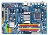
GA-EP45-UD3LR/GA-EP45-UD3L Motherboard Layout KB_MS R_SPDIF R_USB_1 R_USB_2 R_USB_3 ATX_12V LGA775 CPU_FAN PWR_FAN PHASE LED ATX DDR2_1 GA-EP45-UD3LR/GA-EP45-UD3L DDR2_2 DDR2_3 DDR2_4 FDD SYS_FAN2 USB_LAN F_AUDIO SYS_FAN1 AUDIO Intel® P45 RTL8111C PCIEX1_1 PCIEX1_2 PCIEX16 CODEC - Gigabyte GA-EP45-UD3LR | Manual - Page 8
Intel® ICH10 Dual BIOS 6 SATA 3Gb/s 12 USB Ports PCI Bus CODEC LPC Bus IT8718 Floppy LPT Port COM Port PS/2 KB/Mouse Surround Speaker Out Center/Subwoofer Speaker Out Side Speaker Out MIC Line-Out Line-In SPDIF In SPDIF Out 2 PCI PCI CLK (33 MHz) Only for GA-EP45-UD3LR. Only for GA-EP45-UD3L - Gigabyte GA-EP45-UD3LR | Manual - Page 9
manual and follow these procedures: • Prior to installation, do not remove or break motherboard S/N (Serial ESD) wrist strap when handling electronic components such as a motherboard, CPU or memory. If you do not have an ESD steps or have a problem related to the use of the product, please consult - Gigabyte GA-EP45-UD3LR | Manual - Page 10
Celeron® processor in the LGA 775 package (Go to GIGABYTE's website for the latest CPU support list.) L2 cache varies with CPU 1600/1333/1066/800 MHz FSB North Bridge: Intel® P45 Express Chipset South Bridge: Intel® ICH10R /ICH10 4 x 1.8V DDR2 DIMM sockets supporting up to 16 GB of system - Gigabyte GA-EP45-UD3LR | Manual - Page 11
CPU fan header 2 x system fan headers 1 x power fan header 1 x front panel header 1 x front panel audio header 1 x CD In connector 1 x S/PDIF In header 1 x S/PDIF Out header 2 x USB 2.0/1.1 headers 1 x parallel port header 1 x serial port header 1 x power LED header - Gigabyte GA-EP45-UD3LR | Manual - Page 12
, the actual memory size displayed will be less than 4 GB. (Note 2) Whether the CPU/System fan speed control function is supported will depend on the CPU/ System cooler you install. (Note 3) Available functions in EasyTune may differ by motherboard model. GA-EP45-UD3LR/UD3L Motherboard - 12 - - Gigabyte GA-EP45-UD3LR | Manual - Page 13
do so according to your hardware specifications including the CPU, graphics card, memory, hard drive, etc. 1-3-1 Installing the CPU A. Locate the alignment keys on the motherboard CPU socket and the notches on the CPU. LGA775 CPU Socket Alignment Key LGA 775 CPU Alignment Key Pin One Corner of the - Gigabyte GA-EP45-UD3LR | Manual - Page 14
corner of the CPU socket (or you may align the CPU notches with the socket alignment keys) and gently insert the CPU into position. Step 5: Once the CPU is properly inserted, replace the load plate and push the CPU socket lever back into its locked position. GA-EP45-UD3LR/UD3L Motherboard - 14 - - Gigabyte GA-EP45-UD3LR | Manual - Page 15
. Check that the Male and Female push pins are joined closely. (Refer to your CPU cooler installation manual for instructions on installing the cooler.) Step 5: After the installation, check the back of the motherboard. If the push pin is inserted as the picture above, the installation is complete - Gigabyte GA-EP45-UD3LR | Manual - Page 16
, a message which says memory is operating in Flex Memory Mode will appear during the POST. Intel® Flex Memory Technology offers greater flexibility to upgrade by allowing different memory sizes to be populated and remain in Dual Channel mode/performance. GA-EP45-UD3LR/UD3L Motherboard - 16 - - Gigabyte GA-EP45-UD3LR | Manual - Page 17
compatible to DDR DIMMs. Be sure to install DDR2 DIMMs on this motherboard. Notch DDR2 DIMM A DDR2 memory module has a notch, so it can only fit in one direction. Follow the steps below to correctly install your memory modules in the memory sockets. Step 1: Note the orientation of the memory module - Gigabyte GA-EP45-UD3LR | Manual - Page 18
panel with a screw. 5. After installing all expansion cards, replace the chassis cover(s). 6. Turn on your computer. If necessary, go to BIOS Setup to make any required BIOS changes for your expansion card(s). 7. Install the driver straight up from the slot. GA-EP45-UD3LR/UD3L Motherboard - 18 - - Gigabyte GA-EP45-UD3LR | Manual - Page 19
Panel Connectors PS/2 Keyboard and PS/2 Mouse Port Use the upper port (green) to connect a PS/2 mouse and the lower port (purple) to connect a PS/2 keyboard. Optical S/PDIF Out Connector This connector provides digital audio out to an external audio system that supports digital optical audio - Gigabyte GA-EP45-UD3LR | Manual - Page 20
different functions via the audio software. Only microphones still MUST be connected to the default Mic in jack ( ). Refer to the instructions on setting up a 2/4/5.1/ 7.1-channel audio configuration in Chapter 5, "Configuring 2/4/5.1/7.1-Channel Audio." GA-EP45-UD3LR/UD3L Motherboard - 20 - - Gigabyte GA-EP45-UD3LR | Manual - Page 21
ATX 3) CPU_FAN 4) SYS_FAN1/SYS_FAN2 5) PWR_FAN 6) FDD 7) IDE 8) SATA2_0/1/2/3/4/5 9) PWR_LED 10) F_AUDIO 11) F_PANEL 12) CD_IN 13) SPDIF_I 14) SPDIF_O 15) F_USB1/F_USB2 16) LPT 17) COMA 18) CI 19) CLR_CMOS 20) BAT 21) PHASE LED to the connector on the motherboard. - 21 - Hardware Installation - Gigabyte GA-EP45-UD3LR | Manual - Page 22
to the power connector in the correct orientation. The 12V power connector mainly supplies power to the CPU. If the 12V power connector is not connected, the computer will not start. • To meet 5V +5V +5V +5V (Only for 2x12-pinATX) GND (Only for 2x12-pin ATX) GA-EP45-UD3LR/UD3L Motherboard - 22 - - Gigabyte GA-EP45-UD3LR | Manual - Page 23
fan cable, be sure to connect it in the correct orientation (the black connector wire is the ground wire). The motherboard supports CPU fan speed control, which requires the use of a CPU fan with fan speed control design. For optimum heat dissipation, it is recommended that a system fan be installed - Gigabyte GA-EP45-UD3LR | Manual - Page 24
requires at least three hard drives. (The total number of hard drives does not have to be an even number.) • A RAID 10 configuration requires at least four hard drives and the total number of hard drives must be an even number. Only for GA-EP45-UD3LR. GA-EP45-UD3LR/UD3L Motherboard - 24 - - Gigabyte GA-EP45-UD3LR | Manual - Page 25
Each SATA connector supports a single LED keeps blinking when the system is in S1 sleep state. The LED is off when the system is in S3/S4 sleep state or powered off (S5). Pin No. Definition 1 MPD+ 1 2 MPD- 3 MPD- System Status LED S0 On S1 Blinking S3/S4/S5 Off Only for GA-EP45-UD3L - Gigabyte GA-EP45-UD3LR | Manual - Page 26
Audio." • Some chassis provide a front panel audio module that has separated connectors on each wire instead of a single plug. For information about connecting the front panel audio module that has different wire assignments, please contact the chassis manufacturer. GA-EP45-UD3LR/UD3L Motherboard - Gigabyte GA-EP45-UD3LR | Manual - Page 27
startup. If a problem is detected, the BIOS may issue beeps in different patterns to indicate the problem. Refer to Chapter 5, "Troubleshooting," for information about beep codes. • HD (Hard Drive Activity LED, Blue) Connects to the hard drive activity LED on the chassis front panel. The LED is on - Gigabyte GA-EP45-UD3LR | Manual - Page 28
This header supports digital S/PDIF in and can connect to an audio device that supports digital audio out via an optional S/PDIF in cable. For purchasing the optional S/PDIF in cable, please contact the local dealer. 1 Pin No. Definition 1 Power 2 SPDIFI 3 GND GA-EP45-UD3LR/UD3L Motherboard - Gigabyte GA-EP45-UD3LR | Manual - Page 29
14) SPDIF_O (S/PDIF Out Header) This header supports digital S/PDIF out and connects a S/PDIF digital audio cable (provided by expansion cards) for digital audio output from your motherboard to certain expansion cards like graphics cards and sound cards. For example, some graphics cards may require - Gigabyte GA-EP45-UD3LR | Manual - Page 30
) The COM header can provide one serial port via an optional COM port cable. For purchasing the optional COM port cable, please contact the local dealer. 9 1 10 2 Pin No. 1 2 3 4 5 6 7 8 9 10 Definition NDCD NSIN NSOUT NDTR GND NDSR NRTS NCTS NRI No Pin GA-EP45-UD3LR/UD3L Motherboard - 30 - - Gigabyte GA-EP45-UD3LR | Manual - Page 31
the jumper. Failure to do so may cause damage to the motherboard. • After system restart, go to BIOS Setup to load factory defaults (select Load Optimized Defaults) or manually configure the BIOS settings (refer to Chapter 2, "BIOS Setup," for BIOS configurations). - 31 - Hardware Installation - Gigabyte GA-EP45-UD3LR | Manual - Page 32
BIOS LEDs indicates the CPU loading. The higher the CPU loading, the more the number of lighted LEDs. To enable the Phase LED display function, please first enable Dynamic Energy Saver Advanced. Refer to Chapter 4, "Dynamic Energy Saver Advanced," for more details. GA-EP45-UD3LR/UD3L Motherboard - Gigabyte GA-EP45-UD3LR | Manual - Page 33
Windows-based utility that searches and downloads the latest version of BIOS from the Internet and updates the BIOS. For instructions on using the Q-Flash and @BIOS utilities, refer to Chapter 4, "BIOS Update Utilities." • Because BIOS flashing is potentially risky, if you do not encounter problems - Gigabyte GA-EP45-UD3LR | Manual - Page 34
boot order will still be based on BIOS Setup settings. You can access Boot Menu again to change the first boot device setting as needed. : Q-FLASH Press the key to access the Q-Flash utility directly without having to enter BIOS Setup first. GA-EP45-UD3LR/UD3L Motherboard - 34 - - Gigabyte GA-EP45-UD3LR | Manual - Page 35
enter a sub-menu. (Sample BIOS Version: GA-EP45-UD3L E19) CMOS Setup Utility-Copyright Password Set User Password Save & Exit Setup Exit Without Saving ESC: Quit F8: Q-Flash Select Item F10: Save & Exit Setup F11: Save CMOS to BIOS F12: Load CMOS from BIOS Change CPU's Clock & Voltage BIOS - Gigabyte GA-EP45-UD3LR | Manual - Page 36
exit BIOS Setup. (Pressing can also carry out this task.) Exit Without Saving Abandon all changes and the previous settings remain in effect. Pressing to the confirmation message will exit BIOS Setup. (Pressing can also carry out this task.) GA-EP45-UD3LR/UD3L Motherboard - 36 - Gigabyte GA-EP45-UD3LR | Manual - Page 37
CPU Clock Ratio (Note 1) Fine CPU Clock Ratio (Note 1) CPU Clock Control CPU Host Clock Control x CPU Host Frequency CPU Load-Line Calibration [Disabled] CPU Vcore 1.12500V [Auto] CPU Termination 1.200V [Auto] CPU PLL 1.500V [Auto] CPU CPU that supports this feature. (Note 2) This item - Gigabyte GA-EP45-UD3LR | Manual - Page 38
fails to boot after overclocking, please wait for 20 seconds to allow for automated system reboot, or clear the CMOS values to reset the board to default values. (Default: Disabled) (Note) This item appears only if you install a CPU that supports this feature. GA-EP45-UD3LR/UD3L Motherboard - 38 - - Gigabyte GA-EP45-UD3LR | Manual - Page 39
or 11% depending on CPU loading. Turbo Increases CPU frequency by 15% or 17% depending on CPU loading. Full Thrust Increases CPU frequency by 17% or 19% depending on CPU loading. Warning: Before using C.I.A.2, please first verify the overclocking capability of your CPU. As stability is highly - Gigabyte GA-EP45-UD3LR | Manual - Page 40
1000mV. CPU Clock Skew Allows you to set the CPU clock prior the BIOS Manual allows all DRAM timing control items below to be configurable. Options are: Auto (default), Manual. (Note) This item appears only if you install a memory module that supports this feature. GA-EP45-UD3LR/UD3L Motherboard - Gigabyte GA-EP45-UD3LR | Manual - Page 41
: Auto (default), 1~255. tRTP Options are: Auto (default), 1~15. Command Rate(CMD) Options are: Auto (default), 1~3. ******** ESC: Exit F1: General Help F7: Optimized Defaults - 41 - BIOS Setup - Gigabyte GA-EP45-UD3LR | Manual - Page 42
Control Options are: Auto (default), +800ps~-700ps. DIMM2 Clock Skew Control Options are: Auto (default), +800ps~-700ps. ESC: Exit F1: General Help F7: Optimized Defaults GA-EP45-UD3LR/UD3L Motherboard - 42 - - Gigabyte GA-EP45-UD3LR | Manual - Page 43
DDR Write Training Allows you to determine whether to fine-tune memory parameters to enhance memory compatibility. Auto Lets the BIOS decide whether to enable this function. (Default) Disabled Disables this function. Enabled Enables this function to enhance memory compatibility. Channel A/B - Gigabyte GA-EP45-UD3LR | Manual - Page 44
default is Auto. CPU PLL The default is Auto. CPU Reference The default is Auto. >>> MCH/ICH MCH Core The default is Auto. MCH Reference The default is Auto. ICH I/O The default is Auto. ICH Core The default is Auto. >>> DRAM DRAM Voltage The default is Auto. GA-EP45-UD3LR/UD3L Motherboard - 44 - - Gigabyte GA-EP45-UD3LR | Manual - Page 45
4 Slave [None] [None] [None] [None] [None] [None] [None] [None] Drive A Floppy 3 Mode Support [1.44M, 3.5"] [Disabled] Halt On [All, But Keyboard] Base Memory Extended Memory Move Enter: Select F5: Previous Values IDE/SATA devices by using one of the three methods below: - 45 - BIOS Setup - Gigabyte GA-EP45-UD3LR | Manual - Page 46
manually Mode Support Allows BIOS POST. Base Memory Also called conventional memory. Typically, 640 KB will be reserved for the MS-DOS operating system. Extended Memory The amount of extended memory. Total Memory The total amount of memory installed on the system. GA-EP45-UD3LR/UD3L Motherboard - Gigabyte GA-EP45-UD3LR | Manual - Page 47
BIOS Features Hard Disk Boot Priority First Boot Device Second Boot Device Third Boot Device Password Check HDD S.M.A.R.T. Capability CPU Multi-Threading (Note) Limit CPUID Max. to 3 (Note) No-Execute Memory Protect (Note) CPU Enhanced Halt (C1E) (Note) C2/C2E State Support on the list. Press < - Gigabyte GA-EP45-UD3LR | Manual - Page 48
operating system such as Windows NT4.0. (Default: Disabled) No-Execute Memory Protect (Note) Enables or disables Intel® Execute Disable Bit a CPU that supports this feature. For more information about Intel CPUs' unique features, please visit Intel's website. GA-EP45-UD3LR/UD3L Motherboard - 48 - Gigabyte GA-EP45-UD3LR | Manual - Page 49
Delay For HDD (Secs) Allows you to set a delay time for the BIOS to initialize the hard drive as the system boots up. The adjustable range is from 0 to 15 seconds. (Default: ) PEG Sets PCI Express graphics card on the PCI Express x16 slot (PCIEX16_1) as the first display. - 49 - BIOS Setup - Gigabyte GA-EP45-UD3LR | Manual - Page 50
systems that do not support Native mode. (Default) Enabled Allows the SATA controllers to operate in Native IDE mode. Enable Native IDE mode if you wish to install operating systems that support Native mode. Only for GA-EP45-UD3LR. Only for GA-EP45-UD3L. GA-EP45-UD3LR/UD3L Motherboard - 50 - - Gigabyte GA-EP45-UD3LR | Manual - Page 51
audio card instead of using the onboard audio, set this item to Disabled. Onboard H/W LAN Enables or disables the onboard LAN function. (Default: Enabled) If you wish to install a 3rd party add-in network ... If no LAN cable is attached to the motherboard, the Status fields of all four pairs of - Gigabyte GA-EP45-UD3LR | Manual - Page 52
/100/1000 Mbps in Windows mode or when the LAN Boot ROM is activated. When a Cable Problem Occurs... If a cable problem occurs on a specified chip. (Default: Enabled) Onboard Serial Port 1 Enables or disables the first serial port and specifies its base I/O GA-EP45-UD3LR/UD3L Motherboard - 52 - - Gigabyte GA-EP45-UD3LR | Manual - Page 53
Support (Note) HPET Mode (Note) Power On By Mouse Power On By Keyboard x KB Power ON Password AC Back Function EuP Support function, you need an ATX power supply providing at supports wake-up function. (Default: Enabled) (Note) Supported on Windows® Vista® operating system only. - 53 - BIOS Setup - Gigabyte GA-EP45-UD3LR | Manual - Page 54
Enabled, the following four functions will become unavailable: PME event wake up, power on by mouse, power on by keyboard, and wake on LAN. (Note) Supported on Windows® Vista® operating system only. GA-EP45-UD3LR/UD3L Motherboard - 54 - - Gigabyte GA-EP45-UD3LR | Manual - Page 55
IRQ Assignment Auto 3,4,5,7,9,10,11,12,14,15 +/-/PU/PD: Value F10: Save F6: Fail-Safe Defaults ESC: Exit F1: General Help F7: Optimized Defaults BIOS auto-assigns IRQ to the first PCI slot. (Default) Assigns IRQ 3,4,5,7,9,10,11,12,14,15 to the first PCI slot - Gigabyte GA-EP45-UD3LR | Manual - Page 56
), 60oC/140oF, 70oC/158oF, 80oC/176oF, 90oC/194oF. CPU/SYSTEM/POWER FAN Fail Warning Allows the system to emit warning sound if the CPU/system/power fan is not connected or fails. Check the fan condition or fan connection when this occurs. (Default: Disabled) GA-EP45-UD3LR/UD3L Motherboard - 56 - - Gigabyte GA-EP45-UD3LR | Manual - Page 57
. PWM Sets PWM mode for a 4-pin CPU fan. (Default) Note: The Voltage mode can be set for a 3-pin CPU fan or a 4-pin CPU fan. However, for a 4-pin CPU fan that is not designed following Intel PWM fan specifications, selecting PWM mode may not effectively reduce the fan speed. - 57 - BIOS Setup - Gigabyte GA-EP45-UD3LR | Manual - Page 58
on this item and then press the key to load the optimal BIOS default settings. The BIOS defaults settings helps the system to operate in optimum state. Always load the Optimized defaults after updating the BIOS or after clearing the CMOS values. GA-EP45-UD3LR/UD3L Motherboard - 58 - - Gigabyte GA-EP45-UD3LR | Manual - Page 59
allows you to specify two separate passwords: Supervisor Password When a system password is set and the Password Check item in Advanced BIOS Features is set to Setup, you must enter the supervisor password for entering BIOS Setup and making BIOS changes. When the Password Check item is set to System - Gigabyte GA-EP45-UD3LR | Manual - Page 60
F11: Save CMOS to BIOS F12: Load CMOS from BIOS Abandon all Data Press on this item and press the key. This exits the BIOS Setup without saving the changes made in BIOS Setup to the CMOS. Press or to return to the BIOS Setup Main Menu. GA-EP45-UD3LR/UD3L Motherboard - 60 - - Gigabyte GA-EP45-UD3LR | Manual - Page 61
other drivers. • After the drivers are installed, follow the onscreen instructions to restart your system. You can install other applications included in the motherboard driver disk. • For USB 2.0 driver support under the Windows XP operating system, please install the Windows XP Service Pack - Gigabyte GA-EP45-UD3LR | Manual - Page 62
GIGABYTE develops and some free software. You can click the Install button on the right of an item to install it. 3-3 Technical Manuals This page provides GIGABYTE's application guides, content descriptions for this driver disk, and the motherboard manuals. GA-EP45-UD3LR/UD3L Motherboard - 62 - - Gigabyte GA-EP45-UD3LR | Manual - Page 63
3-4 Contact Click the URL on this page to link to the GIGABYTE Web site. Or read the last page of this manual to check the contact information for GIGABYTE Taiwan headquarter or worldwide branch offices. 3-5 System This page provides the basic system information. - 63 - Drivers Installation - Gigabyte GA-EP45-UD3LR | Manual - Page 64
3-6 Download Center To update the BIOS, drivers, or applications, click the Download Center button to link to the GIGABYTE Web site. The latest version of the BIOS, drivers, or applications will be displayed. GA-EP45-UD3LR/UD3L Motherboard - 64 - - Gigabyte GA-EP45-UD3LR | Manual - Page 65
operating system and drivers are installed. • The Windows® XP with SP1 or later • Xpress Recovery and Xpress Recovery2 are different utilities. For example, a backup file created with Xpress Recovery cannot be restored using Xpress Recovery2. • USB hard drives are not supported. • Hard drives in RAID - Gigabyte GA-EP45-UD3LR | Manual - Page 66
Windows XP as the example operating system.) A. Installing Windows XP and Partitioning the Hard Drive 1. Set CD-ROM drive as the first boot device under "Advanced BIOS Features" in the BIOS begin the installation of the operating system (Figure 3). Figure 3 GA-EP45-UD3LR/UD3L Motherboard - 66 - - Gigabyte GA-EP45-UD3LR | Manual - Page 67
4. After the operating system is installed, right-click the My Computer icon on your desktop and select Manage (Figure 4). Go to Computer Management to check disk allocation. Xpress Recovery2 will save the backup file to the unallocated space (black stripe along the top)(Figure 5). Please note that - Gigabyte GA-EP45-UD3LR | Manual - Page 68
operating system. When the Windows operating system is detected, Xpress Recovery2 will begin the backup process (Figure 11). Figure 10 Figure 11 3. When finished, go to Disk Management to check disk allocation. Figure 12 GA-EP45-UD3LR/UD3L Motherboard Xpress Recovery2 will automatically create - Gigabyte GA-EP45-UD3LR | Manual - Page 69
D. Using the Restore Function in Xpress Recovery2 Select RESTORE to restore the backup to your hard drive in case the system breaks down. The RESTORE option will not be present if no backup is created before (Figure 13, 14). Figure 13 Figure 14 E. Removing the Backup 1. If you wish to remove the - Gigabyte GA-EP45-UD3LR | Manual - Page 70
Inc. EP45-UD3L E19 . . . . : BIOS Setup : XpressRecovery2 : Boot Menu : Qflash 09/05/2008-P45-ICH10-7A89PG0UC-00 Because BIOS flashing is potentially risky, please do it with caution. Inadequate BIOS flashing may result in system malfunction. GA-EP45-UD3LR/UD3L Motherboard - 70 - Gigabyte GA-EP45-UD3LR | Manual - Page 71
and press . • The Save Main BIOS to Drive option allows you to save the current BIOS file. • Q-Flash only supports USB flash drive or hard drives using FAT32/16/12 file system. • If the BIOS update file is saved to a hard drive in RAID/AHCI mode or a hard drive attached to an independent - Gigabyte GA-EP45-UD3LR | Manual - Page 72
F11: Save CMOS to BIOS F12: Load CMOS from BIOS Load Optimized Defaults Press to load BIOS defaults Step 6: Select Save & Exit Setup and then press to save settings to CMOS and exit BIOS Setup. The procedure is complete after the system restarts. GA-EP45-UD3LR/UD3L Motherboard - 72 - - Gigabyte GA-EP45-UD3LR | Manual - Page 73
to your location and then download the BIOS file that matches your motherboard model. Follow the on- screen instructions to complete. If the BIOS update file for your motherboard is not present on the @BIOS server site, please manually download the BIOS update file from GIGABYTE's website and - Gigabyte GA-EP45-UD3LR | Manual - Page 74
components such as CPU, chipset, and memory and reduce the useful life of these components. Before you do the overclock/overvoltage, make sure that you fully know each function of EasyTune 6, or system instability or other unexpected results may occur. GA-EP45-UD3LR/UD3L Motherboard - 74 - - Gigabyte GA-EP45-UD3LR | Manual - Page 75
Off) 2 Motherboard Phase LED On/Off Switch (Default: On) 3 Dynamic CPU Frequency Function On/Off Switch (Default: Off) (Note 2) 4 CPU Throttling Display 5 3-Level CPU Voltage Switch (Default:1) (Note 3) 6 CPU Voltage Display 7 Dynamic Power Phase Status 8 Current CPU Power Consumption - Gigabyte GA-EP45-UD3LR | Manual - Page 76
power savings meter is unable to reset to zero. (Note 5) Dynamic Energy Saver Meter will automatically reset when the total power saving reaches 99999999 Watts. GA-EP45-UD3LR/UD3L Motherboard - 76 - - Gigabyte GA-EP45-UD3LR | Manual - Page 77
on the same network, making full use of Internet resources. Directions for using Q-Share After installing Q-Share from the motherboard driver disk, go to shared data folder Changes the data folder to be shared (Note) Updates Q-Share online Displays the current Q-Share version Exits Q-Share ( - Gigabyte GA-EP45-UD3LR | Manual - Page 78
the Microsoft Volume Shadow Copy Services technology, Time Repair allows you to quickly back up and restore your system data in the Windows Vista operating system. Time Repair supports NTFS file system and can so you cannot edit the contents of a shadow copy. GA-EP45-UD3LR/UD3L Motherboard - 78 - - Gigabyte GA-EP45-UD3LR | Manual - Page 79
drive and the other end to an available SATA port on the motherboard. Then connect the power connector from your power supply to the hard drive. Only for GA-EP45-UD3LR. (Note 1) Skip this step if you do not want to create RAID array on the SATA controller. (Note 2) Required when the SATA controller - Gigabyte GA-EP45-UD3LR | Manual - Page 80
Step 2: Save changes and exit BIOS Setup. The BIOS Setup menus described in this section may differ from the exact settings for your motherboard. The actual BIOS Setup menu options you will see shall depend on the motherboard you have and the BIOS version. GA-EP45-UD3LR/UD3L Motherboard - 80 - - Gigabyte GA-EP45-UD3LR | Manual - Page 81
C. Configuring a RAID array in RAID BIOS Enter the RAID BIOS setup utility to configure a RAID array. Skip this step and proceed to the installation of Windows operating system for a non-RAID configuration. Step 1: After the POST memory test begins and before the operating system boot begins, look - Gigabyte GA-EP45-UD3LR | Manual - Page 82
RAID Level : Disks : Strip Size : Capacity : Volume0 RAID0(Stripe) Select Disks 128KB 223.6 GB Create Volume [ HELP ] The following are typical values: RAID0 - 128KB RAID10 - 64KB RAID5 - 64KB []-Change [TAB]-Next [ESC]-Previous Menu Figure 5 [ENTER]-Select GA-EP45-UD3LR/UD3L Motherboard - Gigabyte GA-EP45-UD3LR | Manual - Page 83
Yes Serial # 3JT354CP 3JT329JX Size Type/Status(Vol ID) 111.8GB Member Disk(0) 111.8GB Member Disk(0) []-Select [ESC]-Exit Figure 7 [ENTER]-Select Menu To exit the ICH10R RAID BIOS utility, press or select Exit in MAIN MENU. Now, you may proceed to create the SATA RAID/AHCI driver - Gigabyte GA-EP45-UD3LR | Manual - Page 84
to abort. Intel(R) Matrix Storage Manager option ROM v8.5.0.1013 ICH10R wRAID5 Copyright(C) 2003-08 Intel Corporation. All Rights disks to non-RAID. WARNING: ALL DISK DATA WILL BE DELETED. []-Select [ESC]-Previous Menu Figure 8 [DEL]-Delete Volume GA-EP45-UD3LR/UD3L Motherboard - 84 - - Gigabyte GA-EP45-UD3LR | Manual - Page 85
SATA controller from the motherboard driver disk to a floppy disk. For installing Windows Vista, you first have to copy the SATA controller driver from the motherboard driver disk to your USB flash drive and then extract it (see instructions on the next page). See the instructions below about how to - Gigabyte GA-EP45-UD3LR | Manual - Page 86
?" message, and then press to begin extracting the driver. After the driver is extracted, a screen similar to that in Figure 6 will appear. Figure 5 Figure 6 (Note) To install the Windows Vista 64-bit operating system, please copy the MSM64 file. GA-EP45-UD3LR/UD3L Motherboard - 86 - - Gigabyte GA-EP45-UD3LR | Manual - Page 87
disk containing the SATA RAID/AHCI driver and press (Figure 2). Windows Setup Setup could not determine the type of one or more mass storage devices installed in your system, or you have chosen to manually specify an adapter. Currently, Setup will load support for the following mass storage - Gigabyte GA-EP45-UD3LR | Manual - Page 88
, press S. * If you do not have any device support disks from a mass storage device manufacturer, or do not want to specify additional mass storage devices for use with Windows, press ENTER. S=Specify Additional Device ENTER=Continue F3=Exit Figure 4 GA-EP45-UD3LR/UD3L Motherboard - 88 - - Gigabyte GA-EP45-UD3LR | Manual - Page 89
Step 4: After the SATA RAID/AHCI driver installation is completed, you can proceed with the Windows XP installation. WindowsXP Professional Setup Welcome to Setup. This port of the Setup program prepares Microsoft(R) Windows (R) XP to run on your computer. To set up Windows XP now, press ENTER. To - Gigabyte GA-EP45-UD3LR | Manual - Page 90
disk and perform standard OS installation steps. When a screen similar to that below appears, select Load Driver. (Figure 6). Figure 6 Step 2: Specify the location where the driver is saved, such as your floppy disk or USB flash drive (Figure 7). Figure 7 GA-EP45-UD3LR/UD3L Motherboard - 90 - - Gigabyte GA-EP45-UD3LR | Manual - Page 91
Step 3: When a screen as shown in Figure 8 appears, select Intel(R) ICH8R/ICH9R/ICH10R SATA RAID Controller (Note) and press Next. Figure 8 Step 4: After the driver is loaded, select the RAID/AHCI drive(s) where you want to install the operating system and then press Next to continue the OS - Gigabyte GA-EP45-UD3LR | Manual - Page 92
. • 4-channel audio: Front speaker out and Rear speaker out. • 5.1-channel audio: Front speaker out, Rear speaker out, and Center/Subwoofer speaker out. • 7.1-channel audio: Front speaker out, Rear speaker out, Center/Subwoofer speaker out, and Side speaker out. GA-EP45-UD3LR/UD3L Motherboard - 92 - Gigabyte GA-EP45-UD3LR | Manual - Page 93
OK to complete the configuration. B. Configuring Sound Effect: You may configure an audio environment on the Sound Effect tab. C. Activating an AC'97 Front Panel Audio Module: If your chassis provides an AC'97 front panel audio module, to activate the AC'97 functionality, click the tool icon on the - Gigabyte GA-EP45-UD3LR | Manual - Page 94
audio signals to the computer for audio processing. A. Installing the S/PDIF In Cable: Step 1: First, attach the connector at the end of the cable to the SPDIF_I header on your motherboard. Step 2: Secure the metal bracket to the chassis back panel with a screw. GA-EP45-UD3LR/UD3L Motherboard - Gigabyte GA-EP45-UD3LR | Manual - Page 95
a S/PDIF out Cable Connect a S/PDIF coaxial cable or a S/PDIF optical cable (either one) to an external decoder for transmitting the S/PDIF digital audio signals. S/PDIF Coaxial Cable S/PDIF Optical Cable C. Configuring S/PDIF out: Click the tool icon in the DIGITAL section. In the S/PDIF In/Out - Gigabyte GA-EP45-UD3LR | Manual - Page 96
the front panel. Then configure the jack for microphone functionality. Note: The microphone functions on the front panel and back panel cannot be used at the same time. Step 3: Locate the Volume icon in your system tray and click it to open the volume control panel. GA-EP45-UD3LR/UD3L Motherboard - Gigabyte GA-EP45-UD3LR | Manual - Page 97
using the microphone function on or the front panel, do not select the Mute check box under Front Pink In or Front Green In in Master Volume. It is , go to Options and click Properties. In the Mixer device list, select Realtek HD Audio Input. Then set the recording sound level properly. Do NOT - Gigabyte GA-EP45-UD3LR | Manual - Page 98
Advanced button under a volume control option (e.g. Front Green In, Front Pink In). In the Other Controls field, select Sound Recorder Recording the Sound: 1. Make sure you have connected the audio input device (e.g. microphone) to the computer. 2. On the File GA-EP45-UD3LR/UD3L Motherboard - 98 - - Gigabyte GA-EP45-UD3LR | Manual - Page 99
For more details, go to the Support&Downloads\Motherboards\FAQ page on our website and search for "onboard HD audio driver." Q: What do the beeps emitted during the POST mean? A: The following Award BIOS beep code descriptions may help you identify possible computer problems. (For reference only - Gigabyte GA-EP45-UD3LR | Manual - Page 100
the memory into the memory socket. The problem is verified and solved. Press to enter BIOS Setup. Select "Load Fail-Safe Defaults" (or "Load Optimized Defaults"). Select "Save & Exit Setup" to save changes and exit BIOS Setup. A (Continued...) GA-EP45-UD3LR/UD3L Motherboard - 100 - - Gigabyte GA-EP45-UD3LR | Manual - Page 101
CPU socket might fail. The problem is verified and solved. No The graphics card, expansion slot, or monitor might fail. The problem is verified and solved. Check if the keyboard is working properly. Yes Press to enter BIOS Setup. Select "Load Fail-Safe Defaults" (or "Load Optimized - Gigabyte GA-EP45-UD3LR | Manual - Page 102
contact your local government office, your household waste disposal service or where you purchased the product for details of environmentally the Customer Care number listed in your product's user's manual and we will be glad to help you with your effort. GA-EP45-UD3LR/UD3L Motherboard - 102 - - Gigabyte GA-EP45-UD3LR | Manual - Page 103
Finally, we suggest that you practice other environmentally friendly actions by understanding and using the energy-saving features of this product (where applicable), recycling the inner and outer packaging (including shipping containers) this product was delivered in, and by disposing of or - Gigabyte GA-EP45-UD3LR | Manual - Page 104
GA-EP45-UD3LR/UD3L Motherboard - 104 - - Gigabyte GA-EP45-UD3LR | Manual - Page 105
- 105 - Appendix - Gigabyte GA-EP45-UD3LR | Manual - Page 106
GA-EP45-UD3LR/UD3L Motherboard - 106 - - Gigabyte GA-EP45-UD3LR | Manual - Page 107
- 107 - Appendix - Gigabyte GA-EP45-UD3LR | Manual - Page 108
GA-EP45-UD3LR/UD3L Motherboard - 108 - - Gigabyte GA-EP45-UD3LR | Manual - Page 109
- 109 - Appendix - Gigabyte GA-EP45-UD3LR | Manual - Page 110
GA-EP45-UD3LR/UD3L Motherboard - 110 - - Gigabyte GA-EP45-UD3LR | Manual - Page 111
CO., LTD. Address: No.6, Bau Chiang Road, Hsin-Tien, Taipei 231, Taiwan TEL: +886-2-8912-4000 FAX: +886-2-8912-4003 Tech. and Non-Tech. Support (Sales/Marketing) : http://ggts.gigabyte.com.tw WEB address (English): http://www.gigabyte.com.tw WEB address (Chinese): http://www.gigabyte.tw G.B.T. INC - Gigabyte GA-EP45-UD3LR | Manual - Page 112
in the language list on the top right corner of the website. GIGABYTE Global Service System To submit a technical or non-technical (Sales/ Marketing) question, please link to : http://ggts.gigabyte.com.tw Then select your language to enter the system. GA-EP45-UD3LR/UD3L Motherboard - 112 -
-
 1
1 -
 2
2 -
 3
3 -
 4
4 -
 5
5 -
 6
6 -
 7
7 -
8
-
9
-
10
-
11
-
12
-
13
-
14
-
15
-
16
-
17
-
18
-
19
-
20
-
21
-
22
-
23
-
24
-
25
-
26
-
27
-
28
-
29
-
30
-
31
-
32
-
33
-
34
-
35
-
36
-
37
-
38
-
39
-
40
-
41
-
42
-
43
-
44
-
45
-
46
-
47
-
48
-
49
-
50
-
51
-
52
-
53
-
54
-
55
-
56
-
57
-
58
-
59
-
60
-
61
-
62
-
63
-
64
-
65
-
66
-
67
-
68
-
69
-
70
-
71
-
72
-
73
-
74
-
75
-
76
-
77
-
78
-
79
-
80
-
81
-
82
-
83
-
84
-
85
-
86
-
87
-
88
-
89
-
90
-
91
-
92
-
93
-
94
-
95
-
96
-
97
-
98
-
99
-
100
-
101
-
102
-
103
-
104
-
105
-
106
-
107
-
108
-
109
-
110
-
111
-
112
 |
 |

GA-EP45-UD3LR/
GA-EP45-UD3L
LGA775 socket motherboard for Intel
®
Core
TM
processor family/
Intel
®
Pentium
®
processor family/Intel
®
Celeron
®
processor family
User's Manual
Rev. 1101
12ME-EP45UD3L-1101R