Gigabyte GA-EP45-UD3P Manual
Gigabyte GA-EP45-UD3P Manual
 |
UPC - 818313006530
View all Gigabyte GA-EP45-UD3P manuals
Add to My Manuals
Save this manual to your list of manuals |
Gigabyte GA-EP45-UD3P manual content summary:
- Gigabyte GA-EP45-UD3P | Manual - Page 1
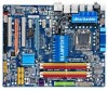
GA-EP45-UD3P/ GA-EP45-UD3R/ GA-EP45-UD3 LGA775 socket motherboard for Intel® Core™ processor family/ Intel® Pentium® processor family/Intel® Celeron® processor family User's Manual Rev. 1601 12ME-EP45U3P-1601R - Gigabyte GA-EP45-UD3P | Manual - Page 2
Motherboard GA-EP45-UD3P/GA-EP45-UD3R/GA-EP45-UD3 Sept. 15, 2008 Motherboard GA-EP45-UD3P/GA-EP45-UD3R/ GA-EP45-UD3 Sept. 15, 2008 - Gigabyte GA-EP45-UD3P | Manual - Page 3
product, read the Quick Installation Guide included with the product. For detailed product information, carefully read the User's Manual. For instructions on how to use GIGABYTE's unique features, read or download the information on/from the Support&Downloads\Motherboard\Technology Guide page on our - Gigabyte GA-EP45-UD3P | Manual - Page 4
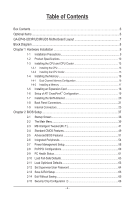
...6 GA-EP45-UD3P/UD3R/UD3 Motherboard Layout 7 Block Diagram...8 Chapter 1 Hardware Installation 9 1-1 Installation Precautions 9 1-2 Product Specifications 10 1-3 Installing the CPU and CPU Cooler 13 1-3-1 Installing the CPU 13 1-3-2 Installing the CPU Cooler 15 1-4 Installing the Memory - Gigabyte GA-EP45-UD3P | Manual - Page 5
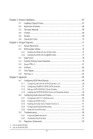
Home Theater Function j 112 5-2-4 Configuring Microphone Recording 113 5-2-5 Using the Sound Recorder 115 5-3 Troubleshooting 116 5-3-1 Frequently Asked Questions 116 5-3-2 Troubleshooting Procedure 117 5-4 Regulatory Statements 119 j Only for GA-EP45-UD3P. k Only for GA-EP45-UD3R. - 5 - - Gigabyte GA-EP45-UD3P | Manual - Page 6
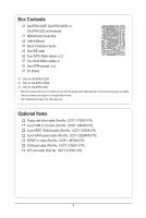
Contents GA-EP45-UD3P, GA-EP45-UD3R, or GA-EP45-UD3 motherboard Motherboard driver disk User's Manual Quick Installation Guide One IDE cable Four SATA 3Gb/s cables jk Two SATA 3Gb/s cables l One SATA bracket jk I/O Shield j Only for GA-EP45-UD3P. k Only for GA-EP45-UD3R. l Only for GA-EP45-UD3 - Gigabyte GA-EP45-UD3P | Manual - Page 7
ATX GA-EP45-UD3P/UD3R/UD3 USB_LAN1 RTL8111C j AUDIO F_AUDIO SYS_FAN1 PCIEX1_1 RTL8111C PCIEX1_2 PCIEX16_1 CODEC PCIEX1_3 BAT SPDIF_O CI PCI1 IT8718 PCIEX8_1 SPDIF_I PCI2 CD_IN Intel® P45 IDE SYS_FAN2 DDR2_3 DDR2_4 GSATA2_0 DDR2_1 DDR2_2 Intel® ICH10R jk Intel® ICH10 l GIGABYTE - Gigabyte GA-EP45-UD3P | Manual - Page 8
BIOS 6 SATA 3Gb/s 12 USB Ports IT8718 Floppy LPT Port COM Port 3 IEEE 1394a PS/2 KB/Mouse Surround Speaker Out Center/Subwoofer Speaker Out Side Speaker Out MIC Line Out Line In S/PDIF In S/ PDIF Out 2 PCI PCI CLK (33 MHz) j Only for GA-EP45-UD3P. k Only for GA-EP45-UD3R. l Only for GA-EP45 - Gigabyte GA-EP45-UD3P | Manual - Page 9
manual and follow these procedures: • Prior to installation, do not remove or break motherboard S/N wrist strap when handling electronic com- ponents such as a motherboard, CPU or memory. If you do not have an ESD wrist strap, steps or have a problem related to the use of the product, please consult - Gigabyte GA-EP45-UD3P | Manual - Page 10
/Intel® Core™ 2 Duo processor/ Intel® Pentium® processor/Intel® Celeron® processor in the LGA775 package (Go to GIGABYTE's website for the latest CPU support list.) L2 cache varies with CPU Front Side Bus w 1600/1333/1066/800 MHz FSB Chipset w North Bridge: Intel® P45 Express Chipset w South - Gigabyte GA-EP45-UD3P | Manual - Page 11
Out connector 8 x USB 2.0/1.1 ports 2 x IEEE 1394a ports 2 x RJ-45 ports j 1 x RJ-45 port kl 6 x audio jacks (Center/Subwoofer Speaker Out/Rear Speaker Out/ Side Speaker Out/Line In/Line Out/Microphone) j Only for GA-EP45-UD3P. k Only for GA-EP45-UD3R. l Only for GA-EP45-UD3. - 11 - Hardware - Gigabyte GA-EP45-UD3P | Manual - Page 12
4cm j Only for GA-EP45-UD3P. (Note 1) Due to Windows Vista/XP 32-bit operating system limitation, when more than 4 GB of physical memory is installed, the actual memory size displayed will be less than 4 GB. (Note 2) For optimum performance, if only one PCI Express graphics card is to be installed - Gigabyte GA-EP45-UD3P | Manual - Page 13
do so according to your hardware specifications including the CPU, graphics card, memory, hard drive, etc. 1-3-1 Installing the CPU A. Locate the alignment keys on the motherboard CPU socket and the notches on the CPU. LGA775 CPU Socket Alignment Key LGA775 CPU Alignment Key Pin One Corner of the - Gigabyte GA-EP45-UD3P | Manual - Page 14
the steps below to correctly install the CPU into the motherboard CPU socket. Before installing the CPU, make sure to turn off the computer and unplug the power cord from the power outlet to prevent damage to the CPU. CPU Socket Lever Step 1: Completely raise the CPU socket lever. Step 2: Lift the - Gigabyte GA-EP45-UD3P | Manual - Page 15
pin. Check that the Male and Female push pins are joined closely. (Refer to your CPU cooler installation manual for instructions on installing the cooler.) Step 5: After the installation, check the back of the motherboard. If the push pin is inserted as the picture above shows, the installation is - Gigabyte GA-EP45-UD3P | Manual - Page 16
following guidelines before you begin to install the memory: • Make sure that the motherboard supports the memory. It is recommended that memory of the same capacity, brand, speed, and chips be used. (Go to GIGABYTE's website for the latest memory support list.) • Always turn off the computer and - Gigabyte GA-EP45-UD3P | Manual - Page 17
the computer and unplug the power cord from the power outlet to prevent damage to the memory module. DDR2 DIMMs are not compatible to DDR DIMMs. Be sure to install DDR2 DIMMs on this motherboard. Notch DDR2 DIMM A DDR2 memory module has a notch, so it can only fit in one direction. Follow the steps - Gigabyte GA-EP45-UD3P | Manual - Page 18
the following guidelines before you begin to install an expansion card: • Make sure the motherboard supports the expansion card. Carefully read the manual that came with your expansion card. • Always turn off the computer and unplug the power cord from the power outlet before installing an expansion - Gigabyte GA-EP45-UD3P | Manual - Page 19
A CrossFireX-supported motherboard with two PCI Express x16 slots and correct driver - Two CrossFireX-ready graphics cards of identical brand and chip and correct driver - Two CrossFire bridge connectors (Note) - A power supply with sufficient power is recommended (Refer to the manual of your - Gigabyte GA-EP45-UD3P | Manual - Page 20
with a screw. Step 2: Connect the SATA cable from the bracket to the SATA port on your motherboard. Step 3: Connect the power cable from the bracket to the power supply. Step 4: Plug one end . jk The SATA bracket is included with the GA-EP45-UD3P/GA-EP45-UD3R only. Hardware Installation - 20 - - Gigabyte GA-EP45-UD3P | Manual - Page 21
LED: State Description Blinking Data transmission or receiving is occurring Off No data transmission or receiving is occurring j Only for GA-EP45-UD3P. • When removing the cable connected to a back panel connector, first remove the cable from your device and then remove it from the motherboard - Gigabyte GA-EP45-UD3P | Manual - Page 22
still MUST be connected to the default Mic in jack ( ). Refer to the instructions on setting up a 2/4/5.1/7.1-channel audio con- figuration in Chapter 5, "Configuring 2/4/5.1/7.1-Channel Audio." j Only for GA-EP45-UD3P. k Only for GA-EP45-UD3R. l Only for GA-EP45-UD3. Hardware Installation - 22 - - Gigabyte GA-EP45-UD3P | Manual - Page 23
SPDIF_O 17) F_USB1/F_USB2 18) F1_1394 19) LPT 20) COMA 21) CI 22) CLR_CMOS 23) PHASE LED Read the following guidelines before connecting external devices: • First make sure your devices are compliant with the been securely attached to the connector on the motherboard. - 23 - Hardware Installation - Gigabyte GA-EP45-UD3P | Manual - Page 24
all the components on the motherboard. Before connecting the power connector start. • Use of a power supply providing a 2x4 12V power connector is recommended by the CPU manufacturer when using an Intel Extreme Edition CPU system. • The power connectors are compatible with power supplies with 2x2 12V - Gigabyte GA-EP45-UD3P | Manual - Page 25
cable, be sure to connect it in the correct orientation (the black connector wire is the ground wire). The motherboard supports CPU fan speed control, which requires the use of a CPU fan with fan speed control design. For optimum heat dissipation, it is recommended that a system fan be installed - Gigabyte GA-EP45-UD3P | Manual - Page 26
3Gb/s standard and are compatible with SATA 1.5Gb/s standard. Each SATA connector supports a single SATA device. SATA2_4 7 7 SATA2_5 SATA2_2 SATA2_3 Pin No. Definition SATA2_0 1 GND 1 2 TXP 3 TXN 1 4 GND SATA2_1 5 RXN 6 RXP 7 GND l Only for GA-EP45-UD3. Hardware Installation - 26 - Gigabyte GA-EP45-UD3P | Manual - Page 27
controller supports RAID 0 and RAID 1. Refer to Chapter 5, "Configuring SATA Hard Drive(s)," for instructions on configuring a RAID array. Pin No. Definition 1 GND 17 2 TXP 3 TXN GSATA2_0 GSATA2_1 4 GND 5 RXN 71 6 RXP 7 GND j Only for GA-EP45-UD3P. k Only for GA-EP45-UD3R. Please - Gigabyte GA-EP45-UD3P | Manual - Page 28
LED S0 On S1 Blinking S3/S4/S5 Off 11) BAT (Battery) The battery provides power to keep the values (such as BIOS configurations, date, and time information) in the CMOS 3. Replace the battery. 4. Plug in the power cord and restart your computer. • Always turn off your computer and unplug the - Gigabyte GA-EP45-UD3P | Manual - Page 29
a beep code. One single short beep will be heard if no problem is detected at system startup. If a problem is detected, the BIOS may issue beeps in different patterns to indicate the problem. Refer to Chapter 5, "Troubleshooting," for information about beep codes. • HD (Hard Drive Activity LED, Blue - Gigabyte GA-EP45-UD3P | Manual - Page 30
pin assignments of the motherboard header. Incorrect connection between the module connector and the motherboard header will make the device front panel audio header supports HD audio by default. If your chassis provides an AC'97 front panel audio module, refer to the instructions on how to activate - Gigabyte GA-EP45-UD3P | Manual - Page 31
(S/PDIF Out Header) This header supports digital S/PDIF Out and connects a S/PDIF digital audio cable (provided by expansion cards) for digital audio output from your motherboard to certain expansion cards like graphics cards and sound cards. For example, some graphics cards may require you to use - Gigabyte GA-EP45-UD3P | Manual - Page 32
local dealer. Pin No. Definition 9 1 10 2 1 TPA+ 2 TPA- 3 GND 4 GND 5 TPB+ 6 TPB- 7 Power (12V) 8 Power (12V) 9 No Pin 10 GND • Do not plug the USB bracket cable into the IEEE 1394a header. • Prior to installing the IEEE 1394a bracket, be sure to turn off your computer and unplug the - Gigabyte GA-EP45-UD3P | Manual - Page 33
19) LPT (Parallel Port Header) The LPT header can provide one parallel port via an optional LPT port cable. For purchasing the optional LPT port cable, please contact the local dealer. 25 1 26 2 Pin No. 1 2 3 4 5 6 7 8 9 10 11 12 13 Definition STBAFDPD0 ERRPD1 INITPD2 SLINPD3 GND PD4 GND PD5 - Gigabyte GA-EP45-UD3P | Manual - Page 34
CMOS values. • After clearing the CMOS values and before turning on your computer, be sure to remove the jumper cap from the jumper. Failure to do so may cause damage to the motherboard. • After system restart, go to BIOS Setup to load factory defaults (select Load Optimized Defaults) or manually - Gigabyte GA-EP45-UD3P | Manual - Page 35
23) PHASE LED The number of lighted LEDs indicates the CPU loading. The higher the CPU loading, the more the number of lighted LEDs. To enable the Phase LED display function, please first enable Dynamic Energy Saver Advanced. Refer to Chapter 4, "Dynamic Energy Saver Advanced," for more details. - - Gigabyte GA-EP45-UD3P | Manual - Page 36
Hardware Installation - 36 - - Gigabyte GA-EP45-UD3P | Manual - Page 37
the GIGABYTE Q-Flash or @BIOS utility. • Q-Flash allows the user to quickly and easily upgrade or back up BIOS without entering the operating system. • @BIOS is a Windows-based utility that searches and downloads the latest version of BIOS from the Internet and updates the BIOS. For instructions on - Gigabyte GA-EP45-UD3P | Manual - Page 38
v6.00PG, An Energy Star Ally Copyright (C) 1984-2009, Award Software, Inc. Motherboard Model BIOS Version EP45-UD3P FAa . . . . : BIOS Setup : XpressRecovery2 : Boot Menu : Qflash 04/29/2009-P45-ICH10-7A89PG0VC-00 Function Keys Function Keys Function Keys: : POST SCREEN - Gigabyte GA-EP45-UD3P | Manual - Page 39
BIOS Version: GA-EP45-UD3P FAa) CMOS Setup Utility-Copyright (C) 1984-2009 Award Software MB Intelligent Tweaker(M.I.T.) Standard CMOS Features Advanced BIOS Select Item F10: Save & Exit Setup Change CPU's Clock & Voltage F11: Save CMOS to BIOS F12: Load CMOS from BIOS BIOS Setup Program - Gigabyte GA-EP45-UD3P | Manual - Page 40
Abandon all changes and the previous settings remain in effect. Pressing to the confirmation message will exit BIOS Setup. (Pressing can also carry out this task.) Security Chip Configuration j Use this menu to configure the TPM function. j Only for GA-EP45-UD3P. BIOS Setup - 40 - - Gigabyte GA-EP45-UD3P | Manual - Page 41
results. (Inadequately altering the settings may result in system's failure to boot. If this occurs, clear the CMOS values and reset the board to default values.) (Note 1) This item appears only if you install a CPU that supports this feature. (Note 2) This item appears only if you install - Gigabyte GA-EP45-UD3P | Manual - Page 42
: If your system fails to boot after overclocking, please wait for 20 seconds to allow for automated system reboot, or clear the CMOS values to reset the board to default values. (Default: Disabled) (Note) This item appears only if you install a CPU that supports this feature. BIOS Setup - 42 - - Gigabyte GA-EP45-UD3P | Manual - Page 43
, set this item to 333 MHz. For a 1600 MHz FSB CPU, set this item to 400 MHz. Important: It is highly recommended that the CPU frequency be set in accordance with the CPU specifications. PCI Express Frequency (Mhz) Allows you to manually set the PCIe clock frequency. The adjustable range is from 90 - Gigabyte GA-EP45-UD3P | Manual - Page 44
the CPU Host Frequency (Mhz) and System Memory Multiplier settings. DRAM Timing Selectable (SPD) Manual allows all DRAM timing control items below to be configurable. Options are: Auto (default), Manual. (Note) This item appears only if you install a memory module that supports this feature. BIOS - Gigabyte GA-EP45-UD3P | Manual - Page 45
1~63. >>>>> Advanced Timing Control Advanced Timing Control CMOS Setup Utility-Copyright (C) 1984-2009 Award Software Advanced Move Enter: Select F5: Previous Values +/-/PU/PD: Value F10: Save F6: Fail-Safe Defaults >>>>> Advanced Timing Control tRRD Defaults - 45 - BIOS Setup - Gigabyte GA-EP45-UD3P | Manual - Page 46
>>>>> Channel A/B Channel A/B Timing Settings CMOS Setup Utility-Copyright (C) 1984-2009 Award Auto Auto Move Enter: Select F5: Previous Values +/-/PU/PD: Value F10: Save F6: Fail-Safe Defaults Static tRead Value Options are: Auto ( General Help F7: Optimized Defaults BIOS Setup - 46 - - Gigabyte GA-EP45-UD3P | Manual - Page 47
memory parameters to enhance memory compatibility. Auto Lets the BIOS decide whether to enable this function. (Default) Enabled Enables this function to enhance memory compatibility. Disabled Disables this function. Channel A/B Driving Settings CMOS +/-/PU/PD: Value F10: Save F6: Fail-Safe - Gigabyte GA-EP45-UD3P | Manual - Page 48
adjusts Vdroop, keeping the CPU voltage more constant under light and heavy CPU load. Disabled sets the CPU voltage following Intel specifications. (Default: Disabled) CPU Vcore The default is Auto. CPU Termination The default is Auto. CPU PLL The default is Auto. CPU Reference The default is Auto - Gigabyte GA-EP45-UD3P | Manual - Page 49
F10: Save F6: Fail-Safe Defaults ESC: Exit F1: General Help F7: Optimized Defaults CMOS Setup Utility-Copyright (C) 1984-2009 Award Software Standard CMOS Features Base Memory Extended Memory Total Memory IDE/SATA devices by using one of the three methods below: - 49 - BIOS Setup - Gigabyte GA-EP45-UD3P | Manual - Page 50
hard drive specifications. If you wish to enter the parameters manually, refer to the information on the hard drive. Capacity Approximate for all other errors. Memory These fields are read-only and are determined by the BIOS POST. Base Memory Also called conventional memory. Typically, 640 KB - Gigabyte GA-EP45-UD3P | Manual - Page 51
CMOS Setup Utility-Copyright (C) 1984-2009 Award Software Advanced BIOS Features } Hard Disk Boot Priority First Boot Device Second Boot Device Third Boot Device Password Check HDD S.M.A.R.T. Capability CPU Multi-Threading (Note) Limit CPUID Max. to 3 (Note) No-Execute Memory - Gigabyte GA-EP45-UD3P | Manual - Page 52
systems that support multi-processor mode. Enabled Enables all CPU cores and multi-threading capability. (Default) Disabled Enables only one CPU core. Limit CPUID Max. to 3 (Note) Allows you to determine whether to limit CPUID maximum value. Set this item to Disabled for Windows XP operating - Gigabyte GA-EP45-UD3P | Manual - Page 53
Show Allows you to determine whether to display the GIGABYTE Logo at system startup. Disabled displays normal POST message. (Default: Enabled) Backup BIOS Image to HDD Allows the system to copy the BIOS image file to the hard drive. If the system BIOS is corrupted, it will be recovered from this - Gigabyte GA-EP45-UD3P | Manual - Page 54
to AHCI mode. Advanced Host Controller Interface (AHCI) is an interface specification that allows the storage driver to enable advanced Serial ATA features such as Native Command Queuing and hot plug. j Only for GA-EP45-UD3P. k Only for GA-EP45-UD3R. l Only for GA-EP45-UD3. BIOS Setup - Gigabyte GA-EP45-UD3P | Manual - Page 55
system will dynamically detect if a LAN cable is connected or not. If not, the corresponding LAN controller will be disabled automatically. (Default: Disabled) j Only for GA-EP45-UD3P. k Only for GA-EP45-UD3R. l Only for GA-EP45-UD3. - 55 - BIOS Setup - Gigabyte GA-EP45-UD3P | Manual - Page 56
F10: Save F6: Fail-Safe Defaults ESC: Exit F1: General Help F7: Optimized Defaults This motherboard the following message will appear: Start detecting at Port..... Link Detected in Windows mode or when the LAN Boot ROM is activated. When a Cable Problem Occurs... If a cable problem occurs - Gigabyte GA-EP45-UD3P | Manual - Page 57
Allows USB mouse to be used in MS-DOS. (Default: Disabled) USB Storage Function Determines whether to detect USB storage devices, including USB flash drives and USB hard drives during the POST. (Default: Enabled) j Only for GA-EP45-UD3P. k Only for GA-EP45-UD3R. l Only for GA-EP45-UD3. - 57 - BIOS - Gigabyte GA-EP45-UD3P | Manual - Page 58
[Enabled] [32-bit mode] [Disabled] [Disabled] Enter [Soft-Off] Item Help Menu Level Move Enter: Select F5: Previous Values +/-/PU/PD: Value F10: Save F6: Fail that supports wake-up function. (Default: Enabled) (Note) Supported on Windows Vista operating system only. BIOS Setup - 58 - - Gigabyte GA-EP45-UD3P | Manual - Page 59
Windows Vista operating system. Select 32-bit mode when you install 32-bit Windows Vista; select 64-bit mode when you install 64-bit Windows Vista. This item is configurable only if the HPET Support is set to Enabled. (Default: 32-bit without entering the password to clear the password settings. AC - Gigabyte GA-EP45-UD3P | Manual - Page 60
: Select F5: Previous Values +/-/PU/PD: Value F10: Save F6: Fail-Safe Defaults ESC: Exit F1: General Help F7: Optimized Defaults PCI1 IRQ Assignment Auto 3,4,5,7,9,10,11,12,14,15 PCI2 IRQ Assignment Auto 3,4,5,7,9,10,11,12,14,15 BIOS auto-assigns IRQ to the first PCI slot - Gigabyte GA-EP45-UD3P | Manual - Page 61
device attached to the motherboard CI header. If the system chassis cover is removed, this field will show "Yes", otherwise it will show "No". To clear the chassis intrusion status record, set Reset Case Open Status to Enabled, save the settings to the CMOS, and then restart your system. Current - Gigabyte GA-EP45-UD3P | Manual - Page 62
Control is set to Enabled or Auto. Auto Lets the BIOS automatically detect the type of CPU fan installed and sets the optimal CPU fan control mode. (Default) Voltage Sets Voltage mode for a 3-pin CPU fan. PWM Sets PWM mode for a 4-pin CPU fan. Note: The Voltage mode can be set for a 3-pin - Gigabyte GA-EP45-UD3P | Manual - Page 63
BIOS settings for the motherboard. 2-11 Load Optimized Defaults CMOS BIOS default settings. The BIOS defaults settings help the system to operate in optimum state. Always load the Optimized defaults after updating the BIOS or after clearing the CMOS values. j Only for GA-EP45-UD3P. - 63 - BIOS - Gigabyte GA-EP45-UD3P | Manual - Page 64
view the BIOS settings but not to make changes. To clear the password, press on the password item and when requested for the password, press again. The message "PASSWORD DISABLED" will appear, indicating the password has been cancelled. j Only for GA-EP45-UD3P. BIOS Setup - 64 - - Gigabyte GA-EP45-UD3P | Manual - Page 65
all Data F11: Save CMOS to BIOS F12: Load CMOS from BIOS Press on this item and press the key. This exits the BIOS Setup without saving the changes made in BIOS Setup to the CMOS. Press or to return to the BIOS Setup Main Menu. j Only for GA-EP45-UD3P. - 65 - BIOS Setup - Gigabyte GA-EP45-UD3P | Manual - Page 66
CMOS Setup Utility-Copyright (C) 1984-2009 Award Software PnP/PCI Configurations Security Chip [Disabled] Item Help Menu Level Security Chip State Disabled/Deactivated Move Enter: Select F5: Previous Values +/-/PU/PD: Value F10 chip. j Only for GA-EP45-UD3P. BIOS Setup - 66 - - Gigabyte GA-EP45-UD3P | Manual - Page 67
recommended drivers. Or click Install Single Items to manually select the drivers instructions to restart your system. You can install other applications included in the motherboard driver disk. • For USB 2.0 driver support under the Windows XP operating system, please install the Windows XP Service - Gigabyte GA-EP45-UD3P | Manual - Page 68
applications that GIGABYTE develops and some free software. You can click the Install button on the right of an item to install it. 3-3 Technical Manuals This page provides GIGABYTE's application guides, content descriptions for this driver disk, and the motherboard manuals. Drivers Installation - Gigabyte GA-EP45-UD3P | Manual - Page 69
3-4 Contact For the detailed contact information of the GIGABYTE Taiwan headquarter or worldwide branch offices, click the URL on this page to link to the GIGABYTE website. 3-5 System This page provides the basic system information. - 69 - Drivers Installation - Gigabyte GA-EP45-UD3P | Manual - Page 70
3-6 Download Center To update the BIOS, drivers, or applications, click the Download Center button to link to the GIGABYTE website. The latest version of the BIOS, drivers, or applications will be displayed. Drivers Installation - 70 - - Gigabyte GA-EP45-UD3P | Manual - Page 71
of system memory • VESA compatible graphics card • Windows XP with SP1 or later, Windows Vista • USB hard drives are not supported. • Hard drives in RAID/AHCI mode are not supported. Installation and Configuration: Turn on your system to boot from the Windows Vista setup disk. A. Installing Windows - Gigabyte GA-EP45-UD3P | Manual - Page 72
Recovery2 cannot save the backup file. B. Accessing Xpress Recovery2 1. Boot from the motherboard driver disk to access Xpress Recovery2 for the first time. When partition to store the backup image file. Step 1: Select BACKUP to start backing up your hard drive data. Step 2: When finished, go to - Gigabyte GA-EP45-UD3P | Manual - Page 73
D. Using the Restore Function in Xpress Recovery2 Select RESTORE to restore the backup to your hard drive in case the system breaks down. The RESTORE option will not be present if no backup is created before. E. Removing the Backup Step 1: If you wish to remove the backup file, select REMOVE. Step - Gigabyte GA-EP45-UD3P | Manual - Page 74
However, if the BIOS update file is saved to a hard drive in RAID/AHCI mode or a hard drive attached to an independent IDE/SATA controller, use the key during the POST to access Q-Flash. Award Modular BIOS v6.00PG, An Energy Star Ally Copyright (C) 1984-2009, Award Software, Inc. EP45-UD3P FAa - Gigabyte GA-EP45-UD3P | Manual - Page 75
key to select Update BIOS from Drive and press . • The Save Main BIOS to Drive option allows you to save the current BIOS file. • Q-Flash only supports USB flash drive or hard drives using FAT32/16/12 file system. • If the BIOS update file is saved to a hard drive in RAID/AHCI mode or a hard - Gigabyte GA-EP45-UD3P | Manual - Page 76
Defaults F11: Save CMOS to BIOS F12: Load CMOS from BIOS Press to load BIOS defaults Step 6: Select Save & Exit Setup and then press to save settings to CMOS and exit BIOS Setup. The procedure is complete after the system restarts. j Only for GA-EP45-UD3P. Unique Features - 76 - Gigabyte GA-EP45-UD3P | Manual - Page 77
. If the BIOS update file for your motherboard is not present on the @BIOS server site, please manually download the BIOS update file from GIGABYTE's website and follow the instructions in "Update the BIOS without Using the Internet Update Function" below. 2. Update the BIOS without Using the - Gigabyte GA-EP45-UD3P | Manual - Page 78
support for Quick Boost. Available functions in EasyTune 6 may differ by motherboard model. Grayed-out area(s) indicates that the item is not configurable or the function is not supported. Incorrectly doing overclock/overvoltage may result in damage to the hardware components such as CPU, chipset - Gigabyte GA-EP45-UD3P | Manual - Page 79
, GIGABYTE Dynamic Energy Saver Advanced shows how much power they have saved in a set period of time. Meter Mode - Button Information Table Button Description 1 Dynamic Energy Saver On/Off Switch (Default: Off) 2 Motherboard Phase LED On/Off Switch (Default: On) 3 Dynamic CPU Frequency - Gigabyte GA-EP45-UD3P | Manual - Page 80
Motherboard Phase LED On/Off Switch (Default: On) 3 Dynamic CPU Frequency Function On/Off Switch (Default: Off) 4 CPU Throttling Display 5 3-Level CPU Voltage Switch (Default:1) (Note 3) 6 CPU Voltage Display 7 Dynamic Power Phase Status 8 Current CPU Utility Update is restarted. Re - Gigabyte GA-EP45-UD3P | Manual - Page 81
the TPM chip is cleared. Be sure to back up the encrypted files first. Step 2: Install the Infineon TPM driver from the motherboard driver disk (select Infineon TPM Driver). Step 3: Install the Smart TPM utility from the motherboard driver disk (select Smart TPM). B. Instructions for using Smart - Gigabyte GA-EP45-UD3P | Manual - Page 82
for using Q-Share After installing Q-Share from the motherboard driver disk, go to Start>All Programs>GIGABYTE>Q-Share. exe to launch the Q-Share tool. shared data folder Changes the data folder to be shared (Note) Updates Q-Share online Displays the current Q-Share version Exits Q-Share ( - Gigabyte GA-EP45-UD3P | Manual - Page 83
Services technology, Time Repair allows you to quickly back up and restore your system data in the Windows Vista operating system. Time Repair supports system restore point upon the first boot up of the day Displays the space. • Each storage volume can accommodate 64 shadow copies. When this limit is - Gigabyte GA-EP45-UD3P | Manual - Page 84
supports the IEEE 802.3ad LACP standard. Please refer to your network switch or router device manual for further details. Select Realtek Ethernet Diagnostic Utility and click Install. Step 1: Insert the motherboard driver click the Remove button. j Only for GA-EP45-UD3P. Unique Features - 84 - - Gigabyte GA-EP45-UD3P | Manual - Page 85
are supported by ICH10R South Bridge.) Then connect the power connector from your power supply to the hard drive. j Only for GA-EP45-UD3P. k Only for GA-EP45-UD3R. (Note 1) Skip this step if you do not want to create RAID array. (Note 2) Required when the SATA controller is set to AHCI or RAID mode - Gigabyte GA-EP45-UD3P | Manual - Page 86
want to create RAID, set this item to Disabled or AHCI. CMOS Setup Utility-Copyright (C) 1984-2009 Award Software Integrated Peripherals SATA RAID/AHCI Mode SATA Port0-3 Native Mode USB Controller USB 2.0 Controller USB Keyboard Support USB Mouse Support Legacy USB storage detect - Gigabyte GA-EP45-UD3P | Manual - Page 87
C. Configuring a RAID array in RAID BIOS Enter the RAID BIOS setup utility to configure a RAID array. Skip this step and proceed with the installation of Windows operating system for a non-RAID configuration. Step 1: After the POST memory test begins and before the operating system boot begins, - Gigabyte GA-EP45-UD3P | Manual - Page 88
16 letters (letters cannot be special characters) under the Name item and press . Then, select a RAID level (Figure 4). There are four RAID levels supported: RAID 0, RAID 1, RAID 10 and RAID 5 (the selections available depend on the number of the hard drives being installed). Press to - Gigabyte GA-EP45-UD3P | Manual - Page 89
Vol ID) Non-RAID Disk Non-RAID Disk [hi]-Select [ESC]-Exit Figure 7 [ENTER]-Select Menu To exit the ICH10R RAID BIOS utility, press or select Exit in MAIN MENU. Now, you can proceed to create the SATA RAID/AHCI driver diskette and install the SATA RAID/AHCI driver and operating system - Gigabyte GA-EP45-UD3P | Manual - Page 90
Volume To delete a RAID array, select Delete RAID Volume in MAIN MENU and press . In the wa[nHt tEoLdPel]ete "Volume0"? (Y/N) : Deleting a volume will reset the disks to non-RAID. WARNING: ALL DISK DATA WILL BE DELETED. [hi]-Select [ESC]-Exit Figure 8 [DEL]-Delete Volume Appendix - - Gigabyte GA-EP45-UD3P | Manual - Page 91
this item to IDE or AHCI. CMOS Setup Utility-Copyright (C) 1984-2009 Award Software Integrated Peripherals SATA RAID/AHCI Mode SATA Port0-3 Native Mode USB Controller USB 2.0 Controller USB Keyboard Support USB Mouse Support Legacy USB storage detect Azalia Codec Onboard - Gigabyte GA-EP45-UD3P | Manual - Page 92
C. Configuring a RAID array in RAID BIOS Enter the RAID BIOS setup utility to configure a RAID array. Skip this step and proceed to the installation of Windows operating system for a non-RAID configuration. After the POST memory test begins and before the operating system boot begins, look for a - Gigabyte GA-EP45-UD3P | Manual - Page 93
Array: In the main screen, press on the Create RAID Disk Drive item. Then the Create New RAID screen appears (Figure 4). GIGABYTE Technology Corp. PCIE-to-SATAII/IDE RAID Controller BIOS v1.06.78 [ Create New RAID ] Name: Level: Disks: Block: Size: GRAID_ 0-Stripe Select Disk 128 KB - Gigabyte GA-EP45-UD3P | Manual - Page 94
arrow key to select the stripe block size (Figure 6), ranging from 4 KB to 128 KB. Press . GIGABYTE Technology Corp. PCIE-to-SATAII/IDE RAID Controller BIOS v1.06.78 [ Create New RAID ] [ Hard Disk Drive List ] Name: Level: Disks: Block: Size: GRAID 0-Stripe Select Disk 128 KB 240 GB - Gigabyte GA-EP45-UD3P | Manual - Page 95
block. Select the array and press . A small window displaying the array information will appear in the center of the screen (Figure 9). GIGABYTE Technology Corp. PCIE-to-SATAII/IDE RAID Controller BIOS v1.06.78 [ Main Menu ] Create RAID Disk Drive Delete RAID Disk Drive Revert HDD to Non - Gigabyte GA-EP45-UD3P | Manual - Page 96
10 [ENTER]-Action [ESC]-Exit Now, you may proceed to create the SATA RAID/AHCI driver diskette and the installation of the SATA RAID/ AHCI driver and operating system. Delete the RAID Array: To delete the array, select Delete RAID Disk Drive in the main menu and press . The selection bar - Gigabyte GA-EP45-UD3P | Manual - Page 97
copy the SATA controller driver from the motherboard driver disk to a USB flash drive. See the instructions below about how to copy the driver in MS-DOS and Windows mode. In MS-DOS mode: Prepare a startup disk that has CD-ROM support and a blank formatted floppy disk. Steps: 1: Boot from the startup - Gigabyte GA-EP45-UD3P | Manual - Page 98
to the previous screen. Intel(R) ICH7R/DH SATA RAID Controller Intel(R) ICH7MDH SATA RAID Controller Intel(R) ICH8R/ICH9R/ICH10R/DO SATA RAID Controller Intel(R) ICH8M-E/ICH9M-E SATA RAID Controller ENTER=Select F3=Exit j Only for GA-EP45-UD3P. k Only for GA-EP45-UD3R. Appendix Figure 2 - 98 - - Gigabyte GA-EP45-UD3P | Manual - Page 99
menu similar to Figure 3 below will appear. Select (Windows XP/2003) RAID/AHCI Driver for GIGABYTE GBB36X Controller and press . Windows Setup You have chosen to configure a SCSI Adapter for use with Windows, using a device support disk provided by an adapter manufacturer. Select the - Gigabyte GA-EP45-UD3P | Manual - Page 100
\iMSM\32Bit For Windows Vista 64-bit, browse to the 64Bit folder. Method B: Insert the USB flash drive containing the driver files and browse to \iMSM\32Bit (for Windows Vista 32-bit) or \iMSM\64Bit (for Windows Vista 64-bit). j Only for GA-EP45-UD3P. k Only for GA-EP45-UD3R. Appendix Figure - Gigabyte GA-EP45-UD3P | Manual - Page 101
Step 3: When a screen as shown in Figure 6 appears, select Intel(R) ICH8R/ICH9R/ICH10R/DO SATA RAID Controller and click Next. Figure 6 Step 4: After the driver is loaded, select the RAID/AHCI drive(s) where you want to install the operating system and then click Next to continue the OS - Gigabyte GA-EP45-UD3P | Manual - Page 102
1: Restart your system to boot from the Windows Vista setup disk and perform standard OS installation steps. When a screen similar to that below appears (RAID/AHCI hard drive(s) will not be detected at this stage), select Load Driver (Figure 8). Figure 8 Step 2: Insert the motherboard driver disk - Gigabyte GA-EP45-UD3P | Manual - Page 103
Step 3: When a screen as shown in Figure 10 appears, select GIGABYTE GBB36X Controller and click Next. Figure 10 Step 4: After the driver is loaded, select the RAID/AHCI drive(s) where you want to install the operating system and then click Next to continue the OS installation (Figure 11). Figure - Gigabyte GA-EP45-UD3P | Manual - Page 104
area, which will show that a RAID volume is being rebuilt). If you do not enable automatic rebuild on this stage, you have to manually rebuild the array in the operating system. [hi]-Select j Only for GA-EP45-UD3P. k Only for GA-EP45-UD3R. Appendix [ESC]-Exit - 104 - [ENTER]-Select Menu - Gigabyte GA-EP45-UD3P | Manual - Page 105
chipset driver has been installed from the motherboard driver disk. Then launch the Intel Matrix Storage Console from All Programs in the Start menu. Drive. Step 3: Click Next when the Rebuild RAID Volume Wizard appears. Follow the on-screen instructions to proceed. Step 4: To check the rebuild - Gigabyte GA-EP45-UD3P | Manual - Page 106
120 GB Status Degraded Members(HDDx) 0? [fgTAB]-Switch Window [hi]-Select RAID [ENTER]-Action [ESC]-Exit Step 2: The selection bar will then move to new hard drive in the Hard Disk Drive List block. Press to start the RAID rebuilding process. The rebuilding progress is displayed at - Gigabyte GA-EP45-UD3P | Manual - Page 107
• Rebuilding in the operating system Make sure the GIGABYTE SATA2 SATA controller driver has been installed from the motherboard driver disk. Launch the GIGABYTE RAID CONFIGURER from All Programs in the Start menu. Step 1: In the GIGABYTE RAID CONFIGURER screen, right-click on the array to be - Gigabyte GA-EP45-UD3P | Manual - Page 108
: Refer to the following for multi-channel speaker configurations. • 2-channel audio: Headphone or Line out. j Only for GA-EP45-UD3P. k Only for GA-EP45-UD3R. l Only for GA-EP45-UD3. • 4-channel audio: Front speaker out and Sidej/Rearkl speaker out. • 5.1-channel audio: Front speaker out, Sidej - Gigabyte GA-EP45-UD3P | Manual - Page 109
Step 2: Connect an audio device to an audio jack. The The current connected device is dialog box appears. Select the device according to the type of device you connect. Then click OK. Step 3: On the Speakers screen, click the Speaker Configuration tab. In the Speaker Configuration list, select - Gigabyte GA-EP45-UD3P | Manual - Page 110
S/PDIF In 1. Installing the S/PDIF In Cable: Step 1: First, attach the connector at the end of the cable to the SPDIF_I header on your motherboard. Step 2: Secure the metal bracket to the chassis back panel with a screw. 2. Configuring S/PDIF In: On the Digital Input screen, click the Default - Gigabyte GA-EP45-UD3P | Manual - Page 111
the S/PDIF digital audio signals. 2. Configuring S/PDIF Out: On the Digital Output screen, click the Default Format tab and then select the sample rate and bit depth. Click OK to complete. - 111 - Appendix - Gigabyte GA-EP45-UD3P | Manual - Page 112
) Install the Dolby GUI Software driver from the motherboard driver disk. Click the Start icon Programs, Dolby Control Center playback. 2. : Click Natural Bass to enable speaker bass effect. j Only for GA-EP45-UD3P. (Note) When Dolby Digital Live is enabled, only digital audio output (S/PDIF) - Gigabyte GA-EP45-UD3P | Manual - Page 113
5-2-4 Configuring Microphone Recording Step 1: After installing the audio driver, the HD Audio Manager icon will appear in the notification area. Double-click the icon to access the HD Audio Manager. Step 2: Connect your microphone - Gigabyte GA-EP45-UD3P | Manual - Page 114
the Microphone Boost icon on the right of the Recording Volume slider and set the Microphone Boost level. Step 5: After completing the settings above, click Start, point to All Programs, point to Accessories, and then click Sound Recorder to begin the sound recording. * Enabling Stereo Mix If the HD - Gigabyte GA-EP45-UD3P | Manual - Page 115
A. Recording Sound 1. Make sure you have connected the sound input device (e.g. microphone) to the computer. 2. To record the audio, click the Start Recording button . 3. To stop recording audio, click the Stop Recording button . Be sure to save the recorded audio file upon completion - Gigabyte GA-EP45-UD3P | Manual - Page 116
mean? A: The following Award BIOS beep code descriptions may help you identify possible computer problems. (For reference only.) 1 short: System boots successfully 2 short: CMOS setting error 1 long, 1 short: Memory or motherboard error 1 long, 2 short: Monitor or graphics card error 1 long, 3 short - Gigabyte GA-EP45-UD3P | Manual - Page 117
Procedure If you encounter any troubles during system startup, follow the troubleshooting procedure below to solve the problem. START Turn off the power. Remove all peripherals, connecting cables, and power cord etc. Make sure the motherboard does not short-circuit with the chassis or - Gigabyte GA-EP45-UD3P | Manual - Page 118
on, is the CPU cooler running? No The power supply, CPU or CPU socket might fail. Yes Check if there is display on your monitor. Yes Turn off the computer. Plug in the keyboard and mouse and restart the computer. The problem is verified and solved. No The graphics card, expansion slot, or - Gigabyte GA-EP45-UD3P | Manual - Page 119
GIGABYTE. Our Commitment to Preserving the Environment In addition to high-efficiency performance, all GIGABYTE motherboards local government office, your household waste disposal service or where you purchased the product for user's manual and we will be glad to help you with your effort. - - Gigabyte GA-EP45-UD3P | Manual - Page 120
Finally, we suggest that you practice other environmentally friendly actions by understanding and using the energy-saving features of this product (where applicable), recycling the inner and outer packaging (including shipping containers) this product was delivered in, and by disposing of or - Gigabyte GA-EP45-UD3P | Manual - Page 121
- 121 - Appendix - Gigabyte GA-EP45-UD3P | Manual - Page 122
Appendix - 122 - - Gigabyte GA-EP45-UD3P | Manual - Page 123
- 123 - Appendix - Gigabyte GA-EP45-UD3P | Manual - Page 124
Appendix - 124 - - Gigabyte GA-EP45-UD3P | Manual - Page 125
- 125 - Appendix - Gigabyte GA-EP45-UD3P | Manual - Page 126
Appendix - 126 - - Gigabyte GA-EP45-UD3P | Manual - Page 127
231, Taiwan TEL: +886-2-8912-4000 FAX: +886-2-8912-4003 Tech. and Non-Tech. Support (Sales/Marketing) : http://ggts.gigabyte.com.tw WEB address (English): http://www.gigabyte.com.tw WEB address (Chinese): http://www.gigabyte.tw • G.B.T. INC. - U.S.A. TEL: +1-626-854-9338 FAX: +1-626-854-9339 Tech - Gigabyte GA-EP45-UD3P | Manual - Page 128
.co.yu • Kazakhstan WEB address : http://www.giga-byte.kz You may go to the GIGABYTE website, select your language in the language list on the top right corner of the website. • GIGABYTE Global Service System To submit a technical or non-technical (Sales/Marketing) question, please link to: http
-
 1
1 -
 2
2 -
 3
3 -
 4
4 -
 5
5 -
 6
6 -
 7
7 -
8
-
9
-
10
-
11
-
12
-
13
-
14
-
15
-
16
-
17
-
18
-
19
-
20
-
21
-
22
-
23
-
24
-
25
-
26
-
27
-
28
-
29
-
30
-
31
-
32
-
33
-
34
-
35
-
36
-
37
-
38
-
39
-
40
-
41
-
42
-
43
-
44
-
45
-
46
-
47
-
48
-
49
-
50
-
51
-
52
-
53
-
54
-
55
-
56
-
57
-
58
-
59
-
60
-
61
-
62
-
63
-
64
-
65
-
66
-
67
-
68
-
69
-
70
-
71
-
72
-
73
-
74
-
75
-
76
-
77
-
78
-
79
-
80
-
81
-
82
-
83
-
84
-
85
-
86
-
87
-
88
-
89
-
90
-
91
-
92
-
93
-
94
-
95
-
96
-
97
-
98
-
99
-
100
-
101
-
102
-
103
-
104
-
105
-
106
-
107
-
108
-
109
-
110
-
111
-
112
-
113
-
114
-
115
-
116
-
117
-
118
-
119
-
120
-
121
-
122
-
123
-
124
-
125
-
126
-
127
-
128
 |
 |

GA-EP45-UD3P/
GA-EP45-UD3R/
GA-EP45-UD3
LGA775 socket motherboard for Intel
®
Core
™
processor family/
Intel
®
Pentium
®
processor family/Intel
®
Celeron
®
processor family
User's Manual
Rev. 1601
12ME-EP45U3P-1601R