Gigabyte GA-EP45T-EXTREME Manual
Gigabyte GA-EP45T-EXTREME Manual
 |
UPC - 818313005878
View all Gigabyte GA-EP45T-EXTREME manuals
Add to My Manuals
Save this manual to your list of manuals |
Gigabyte GA-EP45T-EXTREME manual content summary:
- Gigabyte GA-EP45T-EXTREME | Manual - Page 1
GA-EP45T-EXTREME LGA775 socket motherboard for Intel® CoreTM processor family/ Intel® Pentium® processor family/Intel® Celeron® processor family User's Manual Rev. 1001 12ME-EP45TEXT-1001R - Gigabyte GA-EP45T-EXTREME | Manual - Page 2
Motherboard GA-EP45T-EXTREME Jun. 20, 2008 Motherboard GA-EP45T-EXTREME Jun. 20, 2008 - Gigabyte GA-EP45T-EXTREME | Manual - Page 3
with the product. „ For detailed product information, carefully read the User's Manual. „ For instructions on how to use GIGABYTE's unique features, read or download the information on/from the Support\Motherboard\Technology Guide page on our website. For product-related information, check on our - Gigabyte GA-EP45T-EXTREME | Manual - Page 4
Contents ...6 Optional Items...6 GA-EP45T-EXTREME Motherboard Layout 7 Block Diagram Installing the Memory 17 1-5-1 Dual Channel Memory Configuration 17 1-5-2 Installing a Memory 18 1-6 Features 48 2-5 Advanced BIOS Features 50 2-6 Integrated Peripherals 53 2-7 Power Management Setup 56 2-8 - Gigabyte GA-EP45T-EXTREME | Manual - Page 5
Installation 65 3-1 Installing Chipset Drivers 65 3-2 Application Software 66 3-3 Technical Manuals 66 3-4 Contact ...67 3-5 System ...67 3-6 Download Center 68 Chapter 4 Unique Features 69 4-1 Xpress Recovery2 69 4-2 BIOS Update Utilities 74 4-2-1 Updating the BIOS with the Q-Flash Utility - Gigabyte GA-EP45T-EXTREME | Manual - Page 6
Contents GA-EP45T-EXTREME motherboard Motherboard driver disk User's Manual Quick Installation Guide Intel® LGA775 CPU Installation Guide One -1UB030-51R) 2-port IEEE 1394a bracket (Part No. 12CF1-1IE008-01R) 2-port SATA power cable (Part No. 12CF1-2SERPW-01R) S/PDIF in cable (Part No. 12CR1-1SPDIN-01R - Gigabyte GA-EP45T-EXTREME | Manual - Page 7
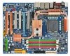
GA-EP45T-EXTREME Motherboard Layout KB_MS R_SPDIF ATX_12V_2X CMOS_SW R_USB LGA775 CPU_FAN FREQUENCY LED CPU Voltage L1/2/3 CPU Temp L1/2 ATX PHASE LED PWR_FAN GA-EP45T- EXTREME USB_LAN2 USB_LAN1 RTL8111C BAT DDR Voltage L1/2/3 AUDIO Intel® P45 F_AUDIO PCIEX1_1 FDD RTL8111C PCI1 - Gigabyte GA-EP45T-EXTREME | Manual - Page 8
RTL 8111C TSB43AB23 IT8213 ATA-133/100/ 3 IEEE 1394a 66/33 IDE Channel Host Interface DDR3 1900 (O.C.)/1600/ 1333/1066/800 MHz Intel® P45 Dual Channel Memory MCH CLK (400/333/266/200 MHz) Intel® ICH10R Dual BIOS 6 SATA 3Gb/s 12 USB Ports CODEC LPC Bus IT8720 Floppy COM Port PS/2 KB/Mouse - Gigabyte GA-EP45T-EXTREME | Manual - Page 9
or memory. If you do not have an ESD wrist strap, keep your hands dry and first touch a metal object to eliminate static electricity. • Prior to installing the motherboard, please have it on top of an antistatic pad or within an electrostatic shielding container. • Before unplugging the power supply - Gigabyte GA-EP45T-EXTREME | Manual - Page 10
: Intel® P45 Express Chipset Š South Bridge: Intel® ICH10R Š 4 x 1.5V DDR3 DIMM sockets supporting up to 16 GB of system memory (Note 1) Š Dual channel memory architecture Š Support for DDR3 1900 (O.C.)/1600/1333/1066/800 MHz memory modules (Go to GIGABYTE's website for the latest memory support - Gigabyte GA-EP45T-EXTREME | Manual - Page 11
the back panel, 4 via the USB brackets connected to the internal USB headers) Internal Connectors Š 1 x 24-pin ATX main power connector Š 1 x 8-pin ATX 12V power connector Š 1 x floppy disk drive connector Š 1 x IDE connector Š 6 x SATA 3Gb/s connectors Š 1 x CPU fan header Š 2 x system fan headers - Gigabyte GA-EP45T-EXTREME | Manual - Page 12
PCI Express x4 card, the PCI Express x1 slot become unavailable. (Note 5) Whether the CPU/system fan speed control function is supported will depend on the CPU/ system cooler you install. (Note 6) Available functions in EasyTune may differ by motherboard model. GA-EP45T-EXTREME Motherboard - 12 - - Gigabyte GA-EP45T-EXTREME | Manual - Page 13
motherboard supports the CPU. (Go to GIGABYTE's website for the latest CPU support list.) • Always turn off the computer and unplug the power cord from the power CPU, graphics card, memory, hard drive, etc. 1-3-1 Installing the CPU A. Locate the alignment keys on the motherboard CPU socket and the - Gigabyte GA-EP45T-EXTREME | Manual - Page 14
to correctly install the CPU into the motherboard CPU socket. Before installing the CPU, make sure to turn off the computer and unplug the power cord from the power outlet to prevent damage to the CPU. push the CPU socket lever back into its locked position. GA-EP45T-EXTREME Motherboard - 14 - - Gigabyte GA-EP45T-EXTREME | Manual - Page 15
CPU cooler on the motherboard. (The following procedure uses Intel® boxed cooler as manual for instructions on installing the cooler.) Step 5: After the installation, check the back of the motherboard power connector of the CPU cooler to the CPU fan header (CPU_FAN) on the motherboard. Use extreme - Gigabyte GA-EP45T-EXTREME | Manual - Page 16
want to connect the front audio module from your chassis to the F_AUDIO connector on the motherboard, be sure to connect it before installing the Hybrid Silent-Pipe module to avoid interference. received may vary in appearance from the products illustrated. GA-EP45T-EXTREME Motherboard - 16 - - Gigabyte GA-EP45T-EXTREME | Manual - Page 17
. If you are unable to insert the memory, switch the direction. 1-5-1 Dual Channel Memory Configuration This motherboard provides four DDR3 memory sockets and supports Dual Channel Technology. After the memory is installed, the BIOS will automatically detect the specifications and capacity of - Gigabyte GA-EP45T-EXTREME | Manual - Page 18
in the picture on the left, place your fingers on the top edge of the memory, push down on the memory and insert it vertically into the memory socket. Step 2: The clips at both ends of the socket will snap into place when the memory module is securely inserted. GA-EP45T-EXTREME Motherboard - 18 - - Gigabyte GA-EP45T-EXTREME | Manual - Page 19
motherboard supports the expansion card. Carefully read the manual that came with your expansion card. • Always turn off the computer and unplug the power cord from the power , go to BIOS Setup to make any required BIOS changes for your expansion card(s). 7. Install the driver provided with the - Gigabyte GA-EP45T-EXTREME | Manual - Page 20
of the SA TA signal cable and SATA power cable to your SATA device. For SA TA device in external enclosure, you only need to connect the SATA signal cable. Before connecting the SATA signal cable, make sure to turn off the power of the external enclosure. GA-EP45T-EXTREME Motherboard - 20 - - Gigabyte GA-EP45T-EXTREME | Manual - Page 21
the clearing CMOS switch to clear CMOS values. USB Port The USB port supports the USB 2.0/1.1 specification. Use this port for USB devices such as an , first remove the cable from your device and then remove it from the motherboard. • When removing the cable, pull it straight out from the connector. - Gigabyte GA-EP45T-EXTREME | Manual - Page 22
perform different functions via the audio software. Only microphones still MUST be connected to the default Mic in jack ( ). Refer to the instructions on setting up a 2/4/5.1/ 7.1-channel audio configuration in Chapter 5, "Configuring 2/4/5.1/7.1-Channel Audio." GA-EP45T-EXTREME Motherboard - 22 - - Gigabyte GA-EP45T-EXTREME | Manual - Page 23
Switches Overvoltage LEDs This motherboard contains 4 sets of overvoltage LEDs which indicate the overvoltage level of the CPU, memory, North Bridge, (High, red) Overclock LEDs The onboard CPU overclock LEDs indicate on which level the CPU is overclocked. The higher the overclock level, the more - Gigabyte GA-EP45T-EXTREME | Manual - Page 24
Quick Switches This motherboard has 3 quick switches: power switch, reset switch and clearing CMOS switch, allowing users to quickly turn on/off or reset the system or clear the CMOS values. PW_SW: Power switch RST_SW: Reset switch CMOS_SW: Clearing CMOS switch - 24 - Hardware Installation - Gigabyte GA-EP45T-EXTREME | Manual - Page 25
with the connectors you wish to connect. • Before installing the devices, be sure to turn off the devices and your computer. Unplug the power cord from the power outlet to prevent damage to the devices. • After installing the device and before turning on the computer, make sure the device cable has - Gigabyte GA-EP45T-EXTREME | Manual - Page 26
+5V 18 GND 19 Power Good 20 5V SB(stand by +5V) 21 +12V 22 +12V (Only for2x12 pinATX) 23 3.3V (Only for 2x12 pinATX) 24 Definition 3.3V -12V GND PS_ON(soft On/Off) GND GND GND -5V +5V +5V +5V (Only for 2x12 pinATX) GND (Only for 2x12 pinATX) GA-EP45T-EXTREME Motherboard - 26 - - Gigabyte GA-EP45T-EXTREME | Manual - Page 27
) system fan headers, and a 3-pin power fan header (PWR_FAN). Most fan headers possess a foolproof insertion design. When connecting a fan cable, be sure to connect it in the correct orientation (the black connector wire is the ground wire). The motherboard supports CPU fan speed control, which - Gigabyte GA-EP45T-EXTREME | Manual - Page 28
stripe of different color. 34 33 2 1 7) IDE (IDE Connector) The IDE connector supports up to two IDE devices such as hard drives and optical drives. Before attaching the IDE the IDE devices, read the instructions from the device manufacturers.) 39 1 40 2 GA-EP45T-EXTREME Motherboard - 28 - - Gigabyte GA-EP45T-EXTREME | Manual - Page 29
compatible with SA TA 1.5Gb/s standard. Each SATA connector supports a single SA TA device. The ICH10R controller supports RAID 0, RAID 1, RAID 5 and RAID 10. Refer to Chapter 5, "Configuring SA TA Hard Drive(s)," for instructions on configuring a RAID array. Pin No. Definition 7 1 SATA2_1 - Gigabyte GA-EP45T-EXTREME | Manual - Page 30
On S1 Blinking S3/S4/S5 Off 10) BAT (BATTERY) The battery provides power to keep the values (such as BIOS configurations, date, and time information) in the CMOS when the computer is turned must be handled in accordance with local environmental regulations. GA-EP45T-EXTREME Motherboard - 30 - - Gigabyte GA-EP45T-EXTREME | Manual - Page 31
positive and negative pins before connecting the cables. Message/Power/ Power Sleep LED Switch Speaker MSG+ MSG- PW+ PWSPEAK problem is detected at system startup. If a problem is detected, the BIOS may issue beeps in different patterns to indicate the problem. Refer to Chapter 5, "Troubleshooting - Gigabyte GA-EP45T-EXTREME | Manual - Page 32
header supports HD audio by default. If your chassis provides an AC'97 front panel audio module, refer to the instructions on how to activate AC'97 functioninality via the audio software in header . 1 Pin No. Definition 1 CD-L 2 GND 3 GND 4 CD-R GA-EP45T-EXTREME Motherboard - 32 - - Gigabyte GA-EP45T-EXTREME | Manual - Page 33
Power 2 SPDIFI 3 GND 15) SPDIF_O (S/PDIF Out Header) This header supports digital S/PDIF out and connects a S/PDIF digital audio cable (provided by expansion cards) for digital audio output from your motherboard carefully read the manual for your expansion card. Pin No. Definition 1 1 - Gigabyte GA-EP45T-EXTREME | Manual - Page 34
the power outlet to prevent damage to the IEEE 1394a bracket. • To connect an IEEE 1394a device, attach one end of the device cable to your computer and then attach the other end of the cable to the IEEE 1394a device. Ensure that the cable is securely connected. GA-EP45T-EXTREME Motherboard - 34 - Gigabyte GA-EP45T-EXTREME | Manual - Page 35
Pin No. 1 2 3 4 5 6 7 8 9 10 Definition NDCD NSIN NSOUT NDTR GND NDSR NRTS NCTS NRI No Pin 19) CI (Chassis Intrusion Header) This motherboard provides a chassis detection feature that detects if the chassis cover has been removed. This function requires a chassis with chassis intrusion detection - Gigabyte GA-EP45T-EXTREME | Manual - Page 36
the power cord from the power outlet manually configure the BIOS settings (refer to Chapter 2, "BIOS Setup," for BIOS configurations). 21) PHASE LED The number of lighted LEDs indicates the CPU loading. The higher the CPU loading, the more the number of lighted LEDs. GA-EP45T-EXTREME Motherboard - Gigabyte GA-EP45T-EXTREME | Manual - Page 37
that searches and downloads the latest version of BIOS from the Internet and updates the BIOS. For instructions on using the Q-Flash and @BIOS utilities, refer to Chapter 4, "BIOS Update Utilities." • Because BIOS flashing is potentially risky, if you do not encounter problems using the current - Gigabyte GA-EP45T-EXTREME | Manual - Page 38
v6.00PG, An Energy Star Ally Copyright (C) 1984-2008, Award Software, Inc. Motherboard Model BIOS Version EP45T-EXTREME D10 . . . . Function Keys : BIOS Setup : XpressRecovery2 : Boot Menu : Qflash 05/30/2008-P45-ICH10-7A89PG0KC-00 Function Keys Function Keys: : POST - Gigabyte GA-EP45T-EXTREME | Manual - Page 39
> to accept or enter a sub-menu. (Sample BIOS Version: D10) CMOS Setup Utility-Copyright (C) 1984-2008 Award Software ` MB Intelligent Tweaker(M.I.T.) ` Standard CMOS Features ` Advanced BIOS Features ` Integrated Peripherals ` Power Management Setup ` PnP/PCI Configurations ` PC Health Status - Gigabyte GA-EP45T-EXTREME | Manual - Page 40
and exit BIOS Setup. (Pressing can also carry out this task.) „ Exit Without Saving Abandon all changes and the previous settings remain in effect. Pressing to the confirmation message will exit BIOS Setup. (Pressing can also carry out this task.) GA-EP45T-EXTREME Motherboard - 40 - Gigabyte GA-EP45T-EXTREME | Manual - Page 41
Extreme Memory Profile (X.M.P.) (Note 2) [Disabled] (G)MCH Frequency Latch [Auto] System Memory Award Software MB Intelligent Tweaker(M.I.T.) Memory Frequency supports this feature. (Note 2) This item appears only if you install a memory module that supports this feature. - 41 - BIOS Setup - Gigabyte GA-EP45T-EXTREME | Manual - Page 42
memory. Auto allows the BIOS overclocking, please wait for 20 seconds to allow for automated system reboot, or clear the CMOS values to reset the board to default values. (Default: Disabled) (Note) This item appears only if you install a CPU that supports this feature. GA-EP45T-EXTREME Motherboard - Gigabyte GA-EP45T-EXTREME | Manual - Page 43
Express Frequency (Mhz) Allows you to manually set the PCIe clock frequency. The adjust CPU computing power to maximize system overclocking, lower the overclocking ratio. >>>>> Advanced Clock Control Advanced Clock Control CMOS Setup Utility-Copyright (C) 1984-2008 Award Software BIOS Setup - Gigabyte GA-EP45T-EXTREME | Manual - Page 44
Mhz) and System Memory Multiplier settings. DRAM Timing Selectable (SPD) Manual allows all DRAM Timing items below to be configurable. Options are: Auto (default), Manual. (Note) This item appears only if you install a memory module that supports this feature. GA-EP45T-EXTREME Motherboard - 44 - - Gigabyte GA-EP45T-EXTREME | Manual - Page 45
default), 1~63. >>>>> Advanced Timing Control Advanced Timing Control CMOS Setup Utility-Copyright (C) 1984-2008 Award Software Advanced Timing Control x tRRD x tWTR x tWR x tRFC x tRTP x Command Rate (CMD) -Safe Defaults - 45 - ESC: Exit F1: General Help F7: Optimized Defaults BIOS Setup - Gigabyte GA-EP45T-EXTREME | Manual - Page 46
Adjustment Options are: Auto (default), 1-Advanced, 0-Normal. tRD Phase1 Adjustment Options are: Auto (default), 1-Advanced, 0-Normal. tRD Phase2 Adjustment Options are: Auto (default), 1-Advanced, 0-Normal. GA-EP45T-EXTREME Motherboard - 46 - - Gigabyte GA-EP45T-EXTREME | Manual - Page 47
default is Auto. Ch-B Data VRef. The default is Auto. Ch-A Address VRef. The default is Auto. Ch-B Address VRef. The default is Auto. - 47 - BIOS Setup - Gigabyte GA-EP45T-EXTREME | Manual - Page 48
Drive A Floppy 3 Mode Support [1.44M, 3.5"] [Disabled] Halt On [All, But Keyboard] Base Memory Extended Memory 640K 510M KLJI: Move Enter Optimized Defaults Total Memory CMOS Setup Utility-Copyright (C) 1984-2008 Award Software Standard CMOS Features GA-EP45T-EXTREME Motherboard - 48 - - Gigabyte GA-EP45T-EXTREME | Manual - Page 49
to enter the parameters manually, refer to the 1.44M/3.5", 2.88M/3.5". Floppy 3 Mode Support Allows you to specify whether the installed floppy Memory it will stop for all other errors. These fields are read-only and are determined by the BIOS POST. Base Memory Also called conventional memory - Gigabyte GA-EP45T-EXTREME | Manual - Page 50
the BIOS Setup program. HDD S.M.A.R.T. Capability Enables or disables the S.M.A.R.T. (Self Monitoring and Reporting Technology) capability CPU that supports this feature. For more information about Intel CPUs' unique features, please visit Intel's website. GA-EP45T-EXTREME Motherboard - 50 - Gigabyte GA-EP45T-EXTREME | Manual - Page 51
exposure to viruses and malicious buffer overflow attacks when working with its supporting software and system. (Default: Enabled) CPU Enhanced Halt (C1E) (Note) Enables or disables Intel ® CPU Enhanced Halt (C1E) function, a CPU power-saving function in system halt state. When enabled, the CPU core - Gigabyte GA-EP45T-EXTREME | Manual - Page 52
the PCI Express x8 slot as the first display. PEG3 Sets PCI Express graphics card on the PCI Express x4 slot as the first display. GA-EP45T-EXTREME Motherboard - 52 - - Gigabyte GA-EP45T-EXTREME | Manual - Page 53
Software Integrated Peripherals SATA RAID/AHCI Mode SATA Port0-3 Native Mode USB Controller USB 2.0 Controller USB Keyboard Support USB Mouse Support the storage driver to enable operating systems that do not support Native mode. (Default) systems that support Native mode. Support Allows USB keyboard to - Gigabyte GA-EP45T-EXTREME | Manual - Page 54
motherboard incorporates cable diagnostic feature designed to detect the status of the attached LAN cable. This feature will detect cabling issue and report the approximate distance to the fault or short. Refer to the following information for diagnosing your LAN cable: GA-EP45T-EXTREME Motherboard - Gigabyte GA-EP45T-EXTREME | Manual - Page 55
to the motherboard, the Status fields of all four pairs of wires will show Open and the Length fields show 0m, as shown in the figure above. When LAN Cable Is Functioning Normally... If no cable problem is detected Auto, 3F8/IRQ4 (default), 2F8/IRQ3, 3E8/IRQ4, 2E8/IRQ3, Disabled. - 55 - BIOS Setup - Gigabyte GA-EP45T-EXTREME | Manual - Page 56
on the +5VSB lead. (Default: Enabled) Power On by Ring Allows the system to be awakened from an ACPI sleep state by a wake-up signal from a modem that supports wake-up function. (Default: Enabled) (Note) Supported on Windows® Vista® operating system only. GA-EP45T-EXTREME Motherboard - 56 - - Gigabyte GA-EP45T-EXTREME | Manual - Page 57
power, or the settings may not be effective. HPET Support you need an ATX power supply providing at least 1A power. (Default) Full-On The system is turned on upon the return of the AC power. Memory The system returns to its last known awake state upon the return of the AC power. (Note) Supported - Gigabyte GA-EP45T-EXTREME | Manual - Page 58
1984-2008 Award Software PnP/PCI BIOS auto-assigns IRQ to the second PCI slot. (Default) Assigns IRQ 3,4,5,7,9,10,11,12,14,15 to the second PCI slot. BIOS auto-assigns IRQ to the third PCI slot. (Default) Assigns IRQ 3,4,5,7,9,10,11,12,14,15 to the third PCI slot. GA-EP45T-EXTREME Motherboard - Gigabyte GA-EP45T-EXTREME | Manual - Page 59
Displays the detection status of the chassis intrusion detection device attached to the motherboard CI header. If the system chassis cover is removed, this field will BIOS will emit warning sound. Options are: Disabled (default), 60 oC/140oF, 70oC/158oF, 80oC/ 176oF, 90oC/194oF. CPU/SYSTEM/POWER - Gigabyte GA-EP45T-EXTREME | Manual - Page 60
only if CPU Smart FAN Control is set to Enabled. Auto Lets BIOS autodetect the type of CPU fan installed and sets the optimal CPU fan is not designed following Intel PWM fan specifications, selecting PWM mode may not effectively reduce the fan speed. GA-EP45T-EXTREME Motherboard - 60 - - Gigabyte GA-EP45T-EXTREME | Manual - Page 61
may try to load Fail-Safe defaults, which are the safest and most stable BIOS settings for the motherboard. 2-11 Load Optimized Defaults CMOS Setup Utility-Copyright (C) 1984-2008 Award Software ` MB Intelligent Tweaker(M.I.T.) Load Fail-Safe Defaults ` Standard CMOS Features Load Optimized - Gigabyte GA-EP45T-EXTREME | Manual - Page 62
you to view the BIOS settings but not to make changes. To clear the password, press on the password item and when requested for the password, press again. The message "PASSWORD DISABLED" will appear, indicating the password has been cancelled. GA-EP45T-EXTREME Motherboard - 62 - - Gigabyte GA-EP45T-EXTREME | Manual - Page 63
BIOS Features Set Supervisor Password ` Integrated Peripherals Save to CMOS and EXIT (SYe/tNU)?seYr Password ` Power Management BIOS Setup program. Press or to return to the BIOS Setup Main Menu. 2-14 Exit Without Saving CMOS Setup Utility-Copyright (C) 1984-2008 Award Software - Gigabyte GA-EP45T-EXTREME | Manual - Page 64
GA-EP45T-EXTREME Motherboard - 64 - - Gigabyte GA-EP45T-EXTREME | Manual - Page 65
other drivers. • After the drivers are installed, follow the onscreen instructions to restart your system. You can install other applications included in the motherboard driver disk. • For USB 2.0 driver support under the Windows XP operating system, please install the Windows XP Service Pack - Gigabyte GA-EP45T-EXTREME | Manual - Page 66
that GIGABYTE develops and some free software. You can click the Install button on the right of an item to install it. 3-3 Technical Manuals This page provides GIGABYTE's application guides, content descriptions for this driver disk, and the motherboard manuals. GA-EP45T-EXTREME Motherboard - 66 - Gigabyte GA-EP45T-EXTREME | Manual - Page 67
3-4 Contact Click the URL on this page to link to the GIGABYTE Web site. Or read the last page of th is manual to check the contact information for GIGABYTE Taiwan headquarter or worldwide branch of fices. 3-5 System This page provides the basic system information. - 67 - Drivers Installation - Gigabyte GA-EP45T-EXTREME | Manual - Page 68
3-6 Download Center To update the BIOS, drivers, or applications, click the Download Center button to link to the GIGABYTE Web site. The latest version of the BIOS, drivers, or applications will be displayed. GA-EP45T-EXTREME Motherboard - 68 - - Gigabyte GA-EP45T-EXTREME | Manual - Page 69
system data and perform restoration of it. Supporting NTFS, FAT32, and FAT16 file systems, your system soon after the operating system and drivers are installed. • The amount of data and hard it. System Requirements: • Intel® platform • At least 64 MB of system memory • VESA compatible graphics card - Gigabyte GA-EP45T-EXTREME | Manual - Page 70
Drive 1. Set CD-ROM drive as the first boot device under "Advanced BIOS Features" in the BIOS Setup program. Save the changes and exit. 2. When partitioning your hard drive example, NTFS) and begin the installation of the operating system (Figure 3). Figure 3 GA-EP45T-EXTREME Motherboard - 70 - - Gigabyte GA-EP45T-EXTREME | Manual - Page 71
4. After the operating system is installed, right-click the My Computer icon on your desktop and select Manage (Figure 4). Go to Computer Management to check disk allocation. Xpress Recovery2 will save the backup file to the unallocated space (black stripe along the top)(Figure 5). Please note that - Gigabyte GA-EP45T-EXTREME | Manual - Page 72
from the motherboard driver disk to Software, Inc. EP45T-EXTREME D10 . . . . : BIOS Setup : XpressRecovery2 : Boot Menu : Qflash 05/30/2008-P45 Management to check disk allocation. Figure 12 GA-EP45T-EXTREME Motherboard Xpress Recovery2 will automatically create a new partition - Gigabyte GA-EP45T-EXTREME | Manual - Page 73
D. Using the Restore Function in Xpress Recovery2 Select RESTORE to restore the backup to your hard drive in case the system breaks down. The RESTORE option will not be present if no backup is created before (Figure 13, 14). Figure 13 Figure 14 E. Removing the Backup 1. If you wish to remove the - Gigabyte GA-EP45T-EXTREME | Manual - Page 74
. EP45T-EXTREME D10 . . . . : BIOS Setup : XpressRecovery2 : Boot Menu : Qflash 05/30/2008-P45-ICH10-7A89PG0KC-00 Because BIOS flashing is potentially risky, please do it with caution. Inadequate BIOS flashing may result in system malfunction. GA-EP45T-EXTREME Motherboard - 74 - Gigabyte GA-EP45T-EXTREME | Manual - Page 75
)SfotounDdrive KL:Move ESC:Reset :Power Off Total size : 0 Free size : 0 3. Select the BIOS update file and press . Make sure the BIOS update file matches your motherboard model. Step 2: The process of the system reading the BIOS file from the floppy disk is displayed - Gigabyte GA-EP45T-EXTREME | Manual - Page 76
F11: Save CMOS to BIOS F12: Load CMOS from BIOS Load Optimized Defaults Press to load BIOS defaults Step 6: Select Save & Exit Setup and then press to save settings to CMOS and exit BIOS Setup. The procedure is complete after the system restarts. GA-EP45T-EXTREME Motherboard - 76 - - Gigabyte GA-EP45T-EXTREME | Manual - Page 77
location and then download the BIOS file that matches your motherboard model. Follow the on- screen instructions to complete. If the BIOS update file for your motherboard is not present on the @BIOS server site, please manually download the BIOS update file from GIGABYTE's website and follow - Gigabyte GA-EP45T-EXTREME | Manual - Page 78
hardware components such as CPU, chipset, and memory and reduce the useful life of these components. Before you do the overclock/overvoltage, make sure that you fully know each function of EasyTune 6, or system instability or other unexpected results may occur. GA-EP45T-EXTREME Motherboard - 78 - - Gigabyte GA-EP45T-EXTREME | Manual - Page 79
technology that delivers unparalleled power savings with a click of the button. Featuring an advanced proprietary hardware and software design, GIGABYTE Dynamic Energy Saver Advanced is able to provide exceptional power savings and enhanced power on motherboard model. • CPU Power and Power Scores - Gigabyte GA-EP45T-EXTREME | Manual - Page 80
will be recorded until re-activated when only the Dynamic Power Saver is under the enable status, and power savings meter is unable to reset to zero. (Note 5) Dynamic Energy Saver Meter will automatically reset when the total power saving reaches 99999999 Watts. GA-EP45T-EXTREME Motherboard - 80 - - Gigabyte GA-EP45T-EXTREME | Manual - Page 81
to another computer simply using Q-Share without making complicated settings. Directions for using Q-Share After installing Q-Share from the motherboard driver disk, go to Start>All Programs>GIGABYTE> Q-Share.exe to launch the Q-Share tool. Find the Q-Share icon in your system tray and right-click - Gigabyte GA-EP45T-EXTREME | Manual - Page 82
the Microsoft Volume Shadow Copy Services technology, Time Repair allows you to quickly back up and restore your system data in the Windows Vista operating system. Time Repair supports NTFS file system and can so you cannot edit the contents of a shadow copy. GA-EP45T-EXTREME Motherboard - 82 - - Gigabyte GA-EP45T-EXTREME | Manual - Page 83
in Windows XP: Select Realtek Ethernet Teaming Utility and click Install. Step 1: Insert the motherboard driver disk and select Application Software, Install Application Software. Click Install under Realtek Ethernet Teaming Util- ity for installation. Restart your system when completed - Gigabyte GA-EP45T-EXTREME | Manual - Page 84
Utility and click Install. Step 1: Insert the motherboard driver disk and select Application Software, Install Application Software. Click Install under Realtek Ethernet Teaming Utility for , access the Realtek Vlan & Teaming Utility and click the Remove button. GA-EP45T-EXTREME Motherboard - 84 - - Gigabyte GA-EP45T-EXTREME | Manual - Page 85
driver disk. 5-1-1 Configuring the Onboard SATA Controller A. Installing SATA hard drive(s) in your computer Attach one end of the SATA signal cable to the rear of the SATA hard drive and the other end to available SATA port on the motherboard. Then connect the power connector from your power supply - Gigabyte GA-EP45T-EXTREME | Manual - Page 86
Step 2: Save changes and exit BIOS Setup. The BIOS Setup menus described in this section may differ from the exact settings for your motherboard. The actual BIOS Setup menu options you will see shall depend on the motherboard you have and the BIOS version. GA-EP45T-EXTREME Motherboard - 86 - - Gigabyte GA-EP45T-EXTREME | Manual - Page 87
BIOS Enter the RAID BIOS setup utility to configure a RAID array. Skip this step and proceed to the installation of Windows operating system for a non-RAID configuration. Step 1: After the POST memory Intel(R) Matrix Storage Manager option ROM v8.5.0.1013 ICH10R wRAID5 Copyright(C) 2003-08 Intel - Gigabyte GA-EP45T-EXTREME | Manual - Page 88
select a RAID level (Figure 4). There are four RAID levels supported: RAID 0, RAID 1, RAID 10 and RAID 5 (the , press . Intel(R) Matrix Storage Manager option ROM v8.5.0.1013 ICH10R wRAID5 Copyright(C) 2003-08 Intel Corporation. All Rights [ENTER]-Select GA-EP45T-EXTREME Motherboard - 88 - - Gigabyte GA-EP45T-EXTREME | Manual - Page 89
6). Intel(R) Matrix Storage Manager option ROM v8.5.0.1013 ICH10R wRAID5 Copyright(C) 2003-08 Intel Corporation Intel(R) Matrix Storage Manager option ROM v8.5.0.1013 ICH10R wRAID5 Copyright(C) 2003-08 Intel Corporation To exit the ICH10R RAID BIOS utility , press or select Exit in MAIN MENU - Gigabyte GA-EP45T-EXTREME | Manual - Page 90
to confirm or to abort. Intel(R) Matrix Storage Manager option ROM v8.5.0.1013 ICH10R wRAID5 Copyright(C) 2003-08 Intel Corporation. All Rights Reversed. [ DELETE VOLUME WILL BE DELETED. [K L ]-Select [ESC]-Previous Menu Figure 8 [DEL]-Delete Volume GA-EP45T-EXTREME Motherboard - 90 - - Gigabyte GA-EP45T-EXTREME | Manual - Page 91
the SA TA controller driver from the motherboard driver disk to your USB flash drive and then extract it (see instructions on the next page). See the instructions below about how to copy the driver in MS-DOS mode . (Note) Prepare a startup disk that has CD-ROM support and a blank formatted floppy - Gigabyte GA-EP45T-EXTREME | Manual - Page 92
?" message, and then press to begin extracting the driver. After the driver is extracted, a screen similar to that in Figure 6 will appear. Figure 5 Figure 6 (Note) To install the Windows V ista 64-bit operating system, please copy the MSM64 file. GA-EP45T-EXTREME Motherboard - 92 - - Gigabyte GA-EP45T-EXTREME | Manual - Page 93
RAID/AHCI driver diskette and configured the required BIOS settings, driver and press (Figure 2). Windows Setup Setup could not determine the type of one or more mass storage devices installed in your system, or you have chosen to manually specify an adapter. Currently, Setup will load support - Gigabyte GA-EP45T-EXTREME | Manual - Page 94
, press S. * If you do not have any device support disks from a mass storage device manufacturer, or do not want to specify additional mass storage devices for use with Windows, press ENTER. S=Specify Additional Device ENTER=Continue F3=Exit Figure 4 GA-EP45T-EXTREME Motherboard - 94 - - Gigabyte GA-EP45T-EXTREME | Manual - Page 95
Step 4: After the SATA RAID/AHCI driver installation is completed, you can proceed with the W indows XP installation. WindowsXP Professional Setup Welcome to Setup. This port of the Setup program prepares Microsoft(R) - Gigabyte GA-EP45T-EXTREME | Manual - Page 96
disk and perform standard OS installation steps. When a screen similar to that below appears, select Load Driver. (Figure 6). Figure 6 Step 2: Specify the location where the driver is saved, such as your floppy disk or USB flash drive (Figure 7). Figure 7 GA-EP45T-EXTREME Motherboard - 96 - - Gigabyte GA-EP45T-EXTREME | Manual - Page 97
Step 3: When a screen as shown in Figure 8 appears, select Intel(R) ICH8R/ICH9R/ICH10R SATA RAID Controller (Note) and press Next. Figure 8 Step 4: After the driver is loaded, select the RAID/AHCI drive(s) where you want to install the operating system and then press Next to continue the OS - Gigabyte GA-EP45T-EXTREME | Manual - Page 98
jack and manually configure the jack for microphone functionality. • If your front panel audio supports Intel HD Audio standard (The following instructions use Windows XP as the example operating system.) Step 1: After installing the audio driver, the Audio GA-EP45T-EXTREME Motherboard - 98 - - Gigabyte GA-EP45T-EXTREME | Manual - Page 99
Step 2: Click the Audio I/O tab. In the speaker list on the left, select 2CH Speaker, 4CH Speaker, 6CH Speaker, or 8CH Speaker according to the type of speaker configuration you wish to set up. Step 3: Everytime you connect an audio device to an audio jack, the Connected device box appears. Select - Gigabyte GA-EP45T-EXTREME | Manual - Page 100
for audio processing. A. Installing the S/PDIF In Cable: Step 1: First, attach the connector at the end of the cable to the SPDIF_I header on your motherboard. Step 2: Secure the metal bracket to the chassis back panel with a screw. GA-EP45T-EXTREME Motherboard - 100 - - Gigabyte GA-EP45T-EXTREME | Manual - Page 101
S/PDIF Out: The S/PDIF out jacks can transmit audio signals to an external decoder for decoding to get the best audio quality. B. Conneting a S/PDIF out Cable Connect a S/PDIF coaxial cable or a S/PDIF optical cable (either one) to an external decoder for transmitting the S/PDIF digital audio - Gigabyte GA-EP45T-EXTREME | Manual - Page 102
playback from two- channel content. B. Windows Vista Install the Dolby GUI Software driver from the motherboard driver disk. Click the Start icon to All Programs, Dolby Control Center to and you will not hear any sound from analog speakers or headphone. GA-EP45T-EXTREME Motherboard - 102 - - Gigabyte GA-EP45T-EXTREME | Manual - Page 103
5-2-4 Configuring Microphone Recording Step 1: After installing the audio driver, the Audio Manager icon will appear in your system tray. Doubleclick the icon to access the Audio Control Panel. Step 2: Connect your microphone to the - Gigabyte GA-EP45T-EXTREME | Manual - Page 104
the Recording option to set the recording sound for your recording device(s) altogether. Select Realtek HD Audio Input in the Mixer device list Recording Control GA-EP45T-EXTREME Motherboard - 104 - - Gigabyte GA-EP45T-EXTREME | Manual - Page 105
Step 6: To raise the recording and playing sound for the microphone, go to Options in Master Volume and select Advanced Controls. Click the Advanced button under a volume control option (e.g. Front Green In, Front Pink In). In the Other Controls field, select the 1 Microphone Boost check box. Step - Gigabyte GA-EP45T-EXTREME | Manual - Page 106
error 1 long, 1 short: Memory or motherboard error 1 long, 2 short: Monitor or graphics card error 1 long, 3 short: Keyboard error 1 long, 9 short: BIOS ROM error Continuous long beeps: Graphics card not inserted properly Continuous short beeps: Power error GA-EP45T-EXTREME Motherboard - 106 - - Gigabyte GA-EP45T-EXTREME | Manual - Page 107
Procedure If you encounter any troubles during system startup, follow the troubleshooting procedure below to solve the problem. START Turn off the power. Remove all peripherals, connecting cables, and power cord etc. Make sure the motherboard does not short-circuit with the chassis or - Gigabyte GA-EP45T-EXTREME | Manual - Page 108
. END If the procedure above is unable to solve your problem, contact the place of purchase or local dealer for help. Or go to the Support\Technical Service Zone page to submit your question. Our customer service staff will reply you as soon as possible. GA-EP45T-EXTREME Motherboard - 108 - - Gigabyte GA-EP45T-EXTREME | Manual - Page 109
registers Detect memory - Auto-detection of DRAM size, type and ECC Expand compressed BIOS code to DRAM Call chipset hook to copy BIOS back to F000 for ESCD & DMI support Use walking 1's algorithm to check out interface in CMOS circuitry. Also set real-time clock power status, and then check for - Gigabyte GA-EP45T-EXTREME | Manual - Page 110
3Eh 40h 43h 47h 49h 4Eh 50h 52h 53h 55h Description Prepare BIOS resource map for PCI & PnP use. If ESCD is valid, take memory (clear all extended memory to 0) Clear password according to H/W jumper (optional) Display number of processors (multi-processor platform) GA-EP45T-EXTREME Motherboard - Gigabyte GA-EP45T-EXTREME | Manual - Page 111
back to text mode if full screen logo is supported - If errors occur, report errors & wait for continue: • Clear EPA or customization logo 1. Call chipset power management hook 2. Recover the text fond used by EP 2. Set up ACPI table at top of the memory 1. Invoke all ISA adapter ROMs 2. Invoke all - Gigabyte GA-EP45T-EXTREME | Manual - Page 112
table 7. Boot BIOS support (popup menu) Update keyboard LED & typematic rate 1. Build MP table 2. Initialize power-saving (optional) 3. Set CMOS century to 20h or 19h 4. Load CMOS time into DOS timer tick 5. Build MSIRQ routing table Boot attempt (INT 19h) GA-EP45T-EXTREME Motherboard - 112 - - Gigabyte GA-EP45T-EXTREME | Manual - Page 113
GIGABYTE. Our Commitment to Preserving the Environment In addition to high-efficiency performance, all GIGABYTE motherboards local government office, your household waste disposal service or where you purchased the product for user's manual and we will be glad to help you with your effort. - - Gigabyte GA-EP45T-EXTREME | Manual - Page 114
hazardous substances are not released into the environment and are disposed of properly. China Restriction of Hazardous Substances Table The following table is supplied in compliance with China's Restriction of Hazardous Substances (China RoHS) requirements: GA-EP45T-EXTREME Motherboard - 114 - - Gigabyte GA-EP45T-EXTREME | Manual - Page 115
- 115 - Appendix - Gigabyte GA-EP45T-EXTREME | Manual - Page 116
GA-EP45T-EXTREME Motherboard - 116 - - Gigabyte GA-EP45T-EXTREME | Manual - Page 117
- 117 - Appendix - Gigabyte GA-EP45T-EXTREME | Manual - Page 118
GA-EP45T-EXTREME Motherboard - 118 - - Gigabyte GA-EP45T-EXTREME | Manual - Page 119
Us Taiwan (Headquarters) GIGA-BYTE TECHNOLOGY CO., LTD. Address: No.6, Bau Chiang Road, Hsin-Tien, Taipei 231, Taiwan TEL: +886-2-8912-4888 FAX: +886-2-8912-4003 Tech. and Non-Tech. Support (Sales/Marketing) : http://ggts.gigabyte.com.tw WEB address (English): http://www.gigabyte.com.tw WEB address - Gigabyte GA-EP45T-EXTREME | Manual - Page 120
language in the language list on the top right corner of the website. GIGABYTE Global Service System To submit a technical or non-technical (Sales/ Marketing) question, please link to : http://ggts.gigabyte.com.tw Then select your language to enter the system. GA-EP45T-EXTREME Motherboard - 120 -
-
 1
1 -
 2
2 -
 3
3 -
 4
4 -
 5
5 -
 6
6 -
 7
7 -
8
-
9
-
10
-
11
-
12
-
13
-
14
-
15
-
16
-
17
-
18
-
19
-
20
-
21
-
22
-
23
-
24
-
25
-
26
-
27
-
28
-
29
-
30
-
31
-
32
-
33
-
34
-
35
-
36
-
37
-
38
-
39
-
40
-
41
-
42
-
43
-
44
-
45
-
46
-
47
-
48
-
49
-
50
-
51
-
52
-
53
-
54
-
55
-
56
-
57
-
58
-
59
-
60
-
61
-
62
-
63
-
64
-
65
-
66
-
67
-
68
-
69
-
70
-
71
-
72
-
73
-
74
-
75
-
76
-
77
-
78
-
79
-
80
-
81
-
82
-
83
-
84
-
85
-
86
-
87
-
88
-
89
-
90
-
91
-
92
-
93
-
94
-
95
-
96
-
97
-
98
-
99
-
100
-
101
-
102
-
103
-
104
-
105
-
106
-
107
-
108
-
109
-
110
-
111
-
112
-
113
-
114
-
115
-
116
-
117
-
118
-
119
-
120
 |
 |

GA-EP45T-EXTREME
LGA775 socket motherboard for Intel
®
Core
TM
processor family/
Intel
®
Pentium
®
processor family/Intel
®
Celeron
®
processor family
User's Manual
Rev. 1001
12ME-EP45TEXT-1001R