Gigabyte GA-EP45T-USB3P Manual
Gigabyte GA-EP45T-USB3P Manual
 |
UPC - 818313010087
View all Gigabyte GA-EP45T-USB3P manuals
Add to My Manuals
Save this manual to your list of manuals |
Gigabyte GA-EP45T-USB3P manual content summary:
- Gigabyte GA-EP45T-USB3P | Manual - Page 1
GA-EP45T-USB3P LGA775 socket motherboard for Intel® Core™ processor family/ Intel® Pentium® processor family/Intel® Celeron® processor family User's Manual Rev. 1001 12ME-45TUS3P-1001R - Gigabyte GA-EP45T-USB3P | Manual - Page 2
Motherboard GA-EP45T-USB3P Dec. 31, 2009 Motherboard GA-EP45T-USB3P Dec. 31, 2009 - Gigabyte GA-EP45T-USB3P | Manual - Page 3
the product. For detailed product information, carefully read the User's Manual. For instructions on how to use GIGABYTE's unique features, read or download the information on/from the Support&Downloads\Motherboard\Technology Guide page on our website. For product-related information, check on our - Gigabyte GA-EP45T-USB3P | Manual - Page 4
Motherboard Layout 7 GA-EP45T-USB3P Motherboard Block Diagram 8 Chapter 1 Hardware Installation 9 1-1 Installation Precautions 9 1-2 Product Specifications 10 1-3 Installing the CPU and CPU Cooler 13 1-3-1 Installing the CPU 13 1-3-2 Installing the CPU Cooler 15 1-4 Installing the Memory BIOS - Gigabyte GA-EP45T-USB3P | Manual - Page 5
...83 5-1 Configuring SATA Hard Drive(s 83 5-1-1 Configuring Intel ICH10R SATA Controllers 83 5-1-2 Configuring GIGABYTE SATA2 SATA Controller 89 5-1-3 Making a SATA RAID/AHCI Driver Diskette 95 5-1-4 Installing the SATA RAID/AHCI Driver and Operating System 96 5-2 Configuring Audio Input and - Gigabyte GA-EP45T-USB3P | Manual - Page 6
Box Contents GA-EP45T-USB3P motherboard Motherboard driver disk User's Manual Quick Installation Guide One IDE cable Four SATA 3Gb/s cables One SATA bracket I/O Shield • The box contents above are for reference only and the actual items shall depend - Gigabyte GA-EP45T-USB3P | Manual - Page 7
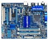
GA-EP45T-USB3P Motherboard Layout KB_MS R_SPDIF ATX_12V_2X4 USB_1394_2 USB_1394_1 R_USB30 NEC D720200F1 CPU_FAN LGA775 PHASE LED PWR_FAN ATX IDE USB CD_IN IT8718 LAN SPDIF_I AUDIO Intel® P45 F_AUDIO RTL8111D SYS_FAN1 PCIEX1_1 GA-EP45T-USB3P PCIEX1_2 PCIEX16 SYS_FAN2 DDR3_1 DDR3_2 - Gigabyte GA-EP45T-USB3P | Manual - Page 8
66/33 IDE Channel Gen 2 NEC D720200F1 2 SATA 3Gb/s GIGABYTE Switch SATA2 x1 Gen 1 PCI Express Bus x1 x1 x1 LGA775 CPU Host Interface Intel® P45 Intel® ICH10R CPU CLK+/(400/333/266/200 MHz) DDR3 2200(O.C.)/1066/1333/800 MHz Dual Channel Memory MCH CLK (333/266/200 MHz) PCI Express Bus x1 - Gigabyte GA-EP45T-USB3P | Manual - Page 9
manual and follow these procedures: • Prior to installation, do not remove or break motherboard S/N wrist strap when handling electronic com- ponents such as a motherboard, CPU or memory. If you do not have an ESD wrist strap, steps or have a problem related to the use of the product, please consult - Gigabyte GA-EP45T-USB3P | Manual - Page 10
in the LGA775 package (Go to GIGABYTE's website for the latest CPU support list.) L2 cache varies with CPU Front Side Bus w 1666/1333/1066/800 MHz FSB Chipset Memory Audio w North Bridge: Intel® P45 Express Chipset w South Bridge: Intel® ICH10R 4 x 1.5V DDR3 DIMM sockets - Gigabyte GA-EP45T-USB3P | Manual - Page 11
USB South Bridge: - Up to 12 USB 2.0/1.1 ports (Note 3) (8 on the back panel, 4 via the USB brackets connected to the internal USB headers) NEC D720200F1 chip: - Up to 2 USB 3.0 ports on the back panel IEEE 1394 T.I. TSB43AB23 chip - Up to 3 IEEE 1394a - Gigabyte GA-EP45T-USB3P | Manual - Page 12
Use of licensed AWARD BIOS Support for DualBIOS™ PnP 1.0a, DMI 2.0, SM BIOS 2.4, ACPI 1.0b Support for @BIOS Support for Q-Flash Support for Xpress BIOS Rescue Support for Download Center Support for Xpress Install Support for Xpress Recovery2 Support for EasyTune (Note 5) Support for Dynamic Energy - Gigabyte GA-EP45T-USB3P | Manual - Page 13
please do so according to your hardware specifications including the CPU, graphics card, memory, hard drive, etc. 1-3-1 Installing the CPU A. Locate the alignment keys on the motherboard CPU socket and the notches on the CPU. LGA775 CPU Socket Alignment Key LGA775 CPU Alignment Key Pin One Corner - Gigabyte GA-EP45T-USB3P | Manual - Page 14
B. Follow the steps below to correctly install the CPU into the motherboard CPU socket. Before installing the CPU, make sure to turn off the computer and unplug the power cord from the power outlet to prevent damage - Gigabyte GA-EP45T-USB3P | Manual - Page 15
below to correctly install the CPU cooler on the motherboard. (The following procedure uses Intel® boxed cooler as the example cooler.) Step 1: CPU cooler installation manual for instructions on installing the cooler.) Step 5: After the installation, check the back of the motherboard. If the push - Gigabyte GA-EP45T-USB3P | Manual - Page 16
This motherboard provides four DDR3 memory sockets and supports Dual Channel Technology. After the memory is installed, the BIOS will automatically detect the specifications and capacity of the memory. Enabling Dual Channel memory mode will double the original memory bandwidth. The four DDR3 memory - Gigabyte GA-EP45T-USB3P | Manual - Page 17
unplug the power cord from the power outlet to prevent damage to the memory module. DDR3 and DDR2 DIMMs are not compatible to each other or DDR DIMMs. Be sure to install DDR3 DIMMs on this motherboard. Notch DDR3 DIMM A DDR3 memory module has a notch, so it can only fit in one direction. Follow the - Gigabyte GA-EP45T-USB3P | Manual - Page 18
an expansion card: • Make sure the motherboard supports the expansion card. Carefully read the manual that came with your expansion card. • Always If necessary, go to BIOS Setup to make any required BIOS changes for your expansion card(s). 7. Install the driver provided with the expansion card - Gigabyte GA-EP45T-USB3P | Manual - Page 19
XP operating system - A CrossFireX-supported motherboard with two PCI Express x16 slots and correct driver - Two CrossFireX-ready graphics cards graphics cards. Procedure and driver screen for enabling CrossFireX technology may differ by graphics cards. Refer to the manual that came with your - Gigabyte GA-EP45T-USB3P | Manual - Page 20
secure the SATA bracket to the chassis back panel with a screw. Step 2: Connect the SATA cable from the bracket to the SATA port on your motherboard. Step 3: Connect the power cable from the bracket to the power supply. Step 4: Plug one end of the SATA signal cable into the external SATA - Gigabyte GA-EP45T-USB3P | Manual - Page 21
for an IEEE 1394a device. USB 2.0/1.1 Port The USB port supports the USB 2.0/1.1 specification. Use this port for USB devices such as a USB keyboard/ , first remove the cable from your device and then remove it from the motherboard. • When removing the cable, pull it straight out from the connector. - Gigabyte GA-EP45T-USB3P | Manual - Page 22
to perform different functions via the audio software. Only microphones still MUST be connected to the default Mic in jack ( ). Refer to the instructions on setting up a 2/4/5.1/7.1-channel audio configuration in Chapter 5, "Configuring 2/4/5.1/7.1-Channel Audio." Hardware Installation - 22 - - Gigabyte GA-EP45T-USB3P | Manual - Page 23
devices. • After installing the device and before turning on the computer, make sure the device cable has been securely attached to the connector on the motherboard. - 23 - Hardware Installation - Gigabyte GA-EP45T-USB3P | Manual - Page 24
2x12 Main Power Connector) With the use of the power connector, the power supply can supply enough stable power to all the components on the motherboard. Before connecting the power connector, first make sure the power supply is turned off and all devices are properly installed. The power connector - Gigabyte GA-EP45T-USB3P | Manual - Page 25
design. When connecting a fan cable, be sure to connect it in the correct orientation (the black connector wire is the ground wire). The motherboard supports CPU fan speed control, which requires the use of a CPU fan with fan speed control design. For optimum heat dissipation, it is recommended - Gigabyte GA-EP45T-USB3P | Manual - Page 26
with SATA 1.5Gb/s standard. Each SATA connector supports a single SATA device. The ICH10R Chipset supports RAID 0, RAID 1, RAID 5, and RAID 10. Refer to Chapter 5, "Configuring SATA Hard Drive(s)," for instructions on configuring a RAID array. SATA2_4 7 7 SATA2_5 SATA2_2 SATA2_3 SATA2_0 SATA2_1 - Gigabyte GA-EP45T-USB3P | Manual - Page 27
supports a single SATA device. The GIGABYTE SATA2 controller supports RAID 0, RAID 1, and JBOD. Refer to Chapter 5, "Configuring SATA Hard Drive(s)," for instructions on configuring a RAID battery provides power to keep the values (such as BIOS configurations, date, and time information) in the CMOS - Gigabyte GA-EP45T-USB3P | Manual - Page 28
a beep code. One single short beep will be heard if no problem is detected at system startup. If a problem is detected, the BIOS may issue beeps in different patterns to indicate the problem. Refer to Chapter 5, "Troubleshooting," for information about beep codes. • HD (Hard Drive Activity LED, Blue - Gigabyte GA-EP45T-USB3P | Manual - Page 29
The front panel audio header supports Intel High Definition audio (HD) and AC'97 audio. You may connect your chassis front panel audio module to this header. Make sure the wire assignments of the module connector match the pin assignments of the motherboard header. Incorrect connection between the - Gigabyte GA-EP45T-USB3P | Manual - Page 30
) This header supports digital S/PDIF Out and connects a S/PDIF digital audio cable (provided by expansion cards) for digital audio output from your motherboard to certain expansion digital audio cable, carefully read the manual for your expansion card. Pin No. Definition 1 SPDIFO 1 2 GND Hardware - Gigabyte GA-EP45T-USB3P | Manual - Page 31
power cord from the power outlet to prevent damage to the USB bracket. 17) F1_1394 (IEEE 1394a Header) The header conforms to IEEE 1394a specification. The IEEE 1394a header can provide one IEEE 1394a port via an optional IEEE 1394a bracket. For purchasing the optional IEEE 1394a bracket, please - Gigabyte GA-EP45T-USB3P | Manual - Page 32
18) LPT (Parallel Port Header) The LPT header can provide one parallel port via an optional LPT port cable. For purchasing the optional LPT port cable, please contact the local dealer. 25 1 26 2 Pin No. 1 2 3 4 5 6 7 8 9 10 11 12 13 Definition STBAFDPD0 ERRPD1 INITPD2 SLINPD3 GND PD4 GND PD5 - Gigabyte GA-EP45T-USB3P | Manual - Page 33
clear the CMOS values (e.g. date information and BIOS configurations) and reset the CMOS values to motherboard. • After system restart, go to BIOS Setup to load factory defaults (select Load Optimized Defaults) or manually configure the BIOS settings (refer to Chapter 2, "BIOS Setup," for BIOS - Gigabyte GA-EP45T-USB3P | Manual - Page 34
Hardware Installation - 34 - - Gigabyte GA-EP45T-USB3P | Manual - Page 35
from the Internet and updates the BIOS. For instructions on using the Q-Flash and @BIOS utilities, refer to Chapter 4, "BIOS Update Utilities." • Because BIOS flashing is potentially risky, if you do not encounter problems using the current version of BIOS, it is recommended that you not flash the - Gigabyte GA-EP45T-USB3P | Manual - Page 36
.00PG, An Energy Star Ally Copyright (C) 1984-2009, Award Software, Inc. Motherboard Model BIOS Version EP45T-USB3P F1a . . . . : BIOS Setup : XpressRecovery2 : Boot Menu : Qflash 12/24/2009-P45-ICH10-6A79PG0CC-00 Function Keys Function Keys Function Keys: : POST SCREEN - Gigabyte GA-EP45T-USB3P | Manual - Page 37
Chip Configuration ESC: Quit F8: Q-Flash Select Item F10: Save & Exit Setup Change CPU's Clock & Voltage F11: Save CMOS to BIOS F12: Load CMOS from BIOS BIOS Setup Program Function Keys Move the selection bar to select an item Execute command or enter the submenu - Gigabyte GA-EP45T-USB3P | Manual - Page 38
the clock, frequency and voltages of your CPU, memory, etc. Standard CMOS Features Use this menu to configure the system time and date, hard drive types, floppy disk drive types, and the type of errors that stop the system boot, etc. Advanced BIOS Features Use this menu to configure the device - Gigabyte GA-EP45T-USB3P | Manual - Page 39
MB Intelligent Tweaker(M.I.T.) Memory Frequency (Mhz) 1333 DRAM Timing Selectable doing overclock/overvoltage may result in damage to CPU, chipset, or memory and supports this feature. (Note 2) This item appears only if you install a memory module that supports this feature. - 39 - BIOS Setup - Gigabyte GA-EP45T-USB3P | Manual - Page 40
to enhance the performance of the graphics chip and memory. Auto allows the BIOS to automatically set the R.G.B. mode based on system below to be configurable. Note: If your system fails to boot after overclocking, please wait for 20 seconds to allow for automated system reboot, or clear - Gigabyte GA-EP45T-USB3P | Manual - Page 41
1333 MHz FSB CPU, set this item to 333 MHz. For a 1600 MHz FSB CPU, set this item to 400 MHz. Important: It is highly recommended that the CPU frequency be set in accordance with the CPU specifications. PCI Express Frequency (Mhz) Allows you to manually overclocking, lower the overclocking BIOS Setup - Gigabyte GA-EP45T-USB3P | Manual - Page 42
Frequency (Mhz) and System Memory Multiplier settings. DRAM Timing Selectable (SPD) Manual allows all DRAM timing control items below to be configurable. Options are: Auto (default), Manual. (Note) This item appears only if you install a memory module that supports this feature. BIOS Setup - 42 - - Gigabyte GA-EP45T-USB3P | Manual - Page 43
: Auto (default), 1~255. tRTP Options are: Auto (default), 1~15. Command Rate(CMD) Options are: Auto (default), 1~3. ESC: Exit F1: General Help F7: Optimized Defaults - 43 - BIOS Setup - Gigabyte GA-EP45T-USB3P | Manual - Page 44
Control Options are: Auto (default), +800ps~-700ps. DIMM2 Clock Skew Control Options are: Auto (default), +800ps~-700ps. ESC: Exit F1: General Help F7: Optimized Defaults BIOS Setup - 44 - - Gigabyte GA-EP45T-USB3P | Manual - Page 45
Leveling Allows you to determine whether to fine-tune memory parameters to enhance memory compatibility. Auto Lets the BIOS decide whether to enable this function. (Default) Enabled Enables this function to enhance memory compatibility. Disabled Disables this function. DDR Write Training Allows - Gigabyte GA-EP45T-USB3P | Manual - Page 46
CPU voltage more constant under light and heavy CPU load. Disabled sets the CPU voltage following Intel specifications. (Default: Disabled) CPU Vcore The default is Auto. CPU Termination The default is Auto. VRef. The default is Auto. Ch-B Address VRef. The default is Auto. BIOS Setup - 46 - - Gigabyte GA-EP45T-USB3P | Manual - Page 47
None] [None] [None] [None] Drive A Floppy 3 Mode Support [1.44M, 3.5"] [Disabled] Halt On [All, But Keyboard] Standard CMOS Features Base Memory Extended Memory Total Memory 640K 1022M 1024M BIOS automatically detect IDE/SATA devices during the POST. (Default) - 47 - Gigabyte GA-EP45T-USB3P | Manual - Page 48
startup. • Manual Allows you to manually enter the specifications of the hard 1.44M/3.5", 2.88M/3.5". Floppy 3 Mode Support Allows you to specify whether the installed floppy Memory These fields are read-only and are determined by the BIOS POST. Base Memory Also called conventional memory - Gigabyte GA-EP45T-USB3P | Manual - Page 49
) No-Execute Memory Protect (Note) CPU Enhanced Halt (C1E) (Note) C2/C2E State Support (Note) x C4/C4E State Support (Note) CPU Thermal Monitor 2(TM2) (Note) CPU EIST Function (Note) Virtualization Technology (Note) Delay For HDD (Secs) Full Screen LOGO Show Backup BIOS Image to - Gigabyte GA-EP45T-USB3P | Manual - Page 50
Intel CPU that supports multi-core technology. This feature only works for operating systems that support No-Execute Memory Protect (Note) Enables or disables Intel Execute Disable Bit supports this feature. For more information about Intel CPUs' unique features, please visit Intel's website. BIOS Setup - Gigabyte GA-EP45T-USB3P | Manual - Page 51
Intel Virtualization Technology will allow a platform to run multiple operating systems and applications in independent partitions. With virtualization, one computer system can function as multiple virtual systems. (Default: Enabled) Delay For HDD (Secs) Allows you to set a delay time for the BIOS - Gigabyte GA-EP45T-USB3P | Manual - Page 52
RAID/AHCI Mode (Intel ICH10R South Bridge) Enables or disables RAID for the SATA controllers integrated in the Intel specification that allows the storage driver to enable advanced Serial ATA features such as Native Command Queuing and hot plug. SATA Port0-3 Native Mode (Intel not support Native - Gigabyte GA-EP45T-USB3P | Manual - Page 53
No LAN Cable Is Attached... If no LAN cable is attached to the motherboard, the Status fields of all four pairs of wires will show Open in the figure above. When LAN Cable Is Functioning Normally... If no cable problem is detected on the LAN cable connected to a Gigabit hub or a 10 53 - BIOS Setup - Gigabyte GA-EP45T-USB3P | Manual - Page 54
to AHCI mode. Advanced Host Controller Interface (AHCI) is an interface specification that allows the storage driver to enable advanced Serial ATA features such as Native Command Queuing and hot plug. RAID/IDE Enables RAID for the SATA controller. (The IDE controller still operates in - Gigabyte GA-EP45T-USB3P | Manual - Page 55
ss) Alarm HPET Support (Note) HPET Mode (Note) Power On x KB Power ON Password AC Back Function EuP Support [S3(STR)] [Instant-Off] [Enabled] [Enabled supports wake-up function. (Default: Enabled) (Note) Supported on Windows 7/Vista operating system only. - 55 - Gigabyte GA-EP45T-USB3P | Manual - Page 56
Month) Alarm: Turn on the system at a specific time on each day or on a specific day in a month. Time (hh: mm: ss Memory The system returns to its last known awake state upon the return of the AC power. EuP Support Determines Supported on Windows 7/Vista operating system only. BIOS Setup - 56 - - Gigabyte GA-EP45T-USB3P | Manual - Page 57
: Exit F1: General Help F7: Optimized Defaults PCI1 IRQ Assignment Auto 3,4,5,7,9,10,11,12,14,15 PCI2 IRQ Assignment Auto 3,4,5,7,9,10,11,12,14,15 BIOS auto-assigns IRQ to the first PCI slot. (Default) Assigns IRQ 3,4,5,7,9,10,11,12,14,15 to the first PCI slot - Gigabyte GA-EP45T-USB3P | Manual - Page 58
Displays the detection status of the chassis intrusion detection device attached to the motherboard CI header. If the system chassis cover is removed, this field or disables the CPU fan speed control function. Auto lets the BIOS decide whether to enable this function. Enabled allows the CPU fan to - Gigabyte GA-EP45T-USB3P | Manual - Page 59
if CPU Smart FAN Control is set to Enabled or Auto. Auto Lets the BIOS automatically detect the type of CPU fan installed and sets the optimal CPU fan control CPU fan that is not designed following Intel PWM fan specifications, selecting PWM mode may not effectively reduce the fan speed. - 59 - Gigabyte GA-EP45T-USB3P | Manual - Page 60
. In case system instability occurs, you may try to load Fail-Safe defaults, which are the safest and most stable BIOS settings for the motherboard. 2-11 Load Optimized Defaults CMOS Setup Utility-Copyright (C) 1984-2009 Award Software MB Intelligent Tweaker(M.I.T.) Load Fail-Safe Defaults - Gigabyte GA-EP45T-USB3P | Manual - Page 61
changes. When the Password Check item is set to System, you must enter the supervisor password (or user password) at system startup and when entering BIOS Setup. User Password When the Password Check item is set to System, you must enter the supervisor password (or user password) at system startup - Gigabyte GA-EP45T-USB3P | Manual - Page 62
Saving PC Health Status Security Chip Configuration ESC: Quit F8: Q-Flash Select Item F10: Save & Exit Setup Save Data to CMOS F11: Save CMOS to BIOS F12: Load CMOS from BIOS Press on this item and press the key. This saves the changes to the CMOS and exits the - Gigabyte GA-EP45T-USB3P | Manual - Page 63
security chip and initializes the Security Platform. Disabled Disables the security chip. (Default) Security Chip State Displays the current settings in the security chip. - 63 - BIOS Setup - Gigabyte GA-EP45T-USB3P | Manual - Page 64
BIOS Setup - 64 - - Gigabyte GA-EP45T-USB3P | Manual - Page 65
recommended drivers. Or click Install Single Items to manually select the drivers instructions to restart your system. You can install other applications included in the motherboard driver disk. • For USB 2.0 driver support under the Windows XP operating system, please install the Windows XP Service - Gigabyte GA-EP45T-USB3P | Manual - Page 66
applications that GIGABYTE develops and some free software. You can click the Install button on the right of an item to install it. 3-3 Technical Manuals This page provides GIGABYTE's application guides, content descriptions for this driver disk, and the motherboard manuals. Drivers Installation - Gigabyte GA-EP45T-USB3P | Manual - Page 67
3-4 Contact For the detailed contact information of the GIGABYTE Taiwan headquarter or worldwide branch offices, click the URL on this page to link to the GIGABYTE website. 3-5 System This page provides the basic system information. - 67 - Drivers Installation - Gigabyte GA-EP45T-USB3P | Manual - Page 68
, or applications, click the Download Center button to link to the GIGABYTE website. The latest version of the BIOS, drivers, or applications will be displayed. 3-7 New Utilities This page provides a quick link to GIGABYTE's lately developed utilities for users to install. You can click the Install - Gigabyte GA-EP45T-USB3P | Manual - Page 69
up your system soon after the operating system and drivers are installed. • The amount of data and hard System Requirements: • At least 512 MB of system memory • VESA compatible graphics card • Windows XP with SP1 are not supported. • Hard drives in RAID/AHCI mode are not supported. Installation and - Gigabyte GA-EP45T-USB3P | Manual - Page 70
note that if there is no enough unallocated space, Xpress Recovery2 cannot save the backup file. B. Accessing Xpress Recovery2 1. Boot from the motherboard driver disk to access Xpress Recovery2 for the first time. When you see the following message: Press any key to startup Xpress Recovery2, press - Gigabyte GA-EP45T-USB3P | Manual - Page 71
D. Using the Restore Function in Xpress Recovery2 Select RESTORE to restore the backup to your hard drive in case the system breaks down. The RESTORE option will not be present if no backup is created before. E. Removing the Backup Step 1: If you wish to remove the backup file, select REMOVE. Step - Gigabyte GA-EP45T-USB3P | Manual - Page 72
1984-2009, Award Software, Inc. EP45T-USB3P F1a . . . . : BIOS Setup : XpressRecovery2 : Boot Menu : Qflash 12/24/2009-P45-ICH10-6A79PG0CC-00 Because BIOS flashing is potentially risky, please do it with caution. Inadequate BIOS flashing may result in system malfunction. Unique - Gigabyte GA-EP45T-USB3P | Manual - Page 73
and press . • The Save Main BIOS to Drive option allows you to save the current BIOS file. • Q-Flash only supports USB flash drive or hard drives using FAT32/16/12 file system. • If the BIOS update file is saved to a hard drive in RAID/AHCI mode or a hard drive attached to an independent - Gigabyte GA-EP45T-USB3P | Manual - Page 74
Health Status Security Chip Configuration ESC: Quit F8: Q-Flash Select Item F10: Save & Exit Setup Load Optimized Defaults F11: Save CMOS to BIOS F12: Load CMOS from BIOS Press to load BIOS defaults Step 6: Select Save & Exit Setup and then press to save settings to CMOS and exit - Gigabyte GA-EP45T-USB3P | Manual - Page 75
model. Follow the on-screen instructions to complete. If the BIOS update file for your motherboard is not present on the @BIOS server site, please manually download the BIOS update file from GIGABYTE's website and follow the instructions in "Update the BIOS without Using the Internet Update - Gigabyte GA-EP45T-USB3P | Manual - Page 76
install a DDR3 1066 MHz memory module(s) (or above) to enable support for Quick Boost. Available functions in EasyTune 6 may differ by motherboard model. Grayed-out area(s) indicates that the item is not configurable or the function is not supported. Incorrectly doing overclock/overvoltage may - Gigabyte GA-EP45T-USB3P | Manual - Page 77
technology that delivers unparalleled power savings with a click of the button. Featuring an advanced proprietary hardware and software design, GIGABYTE above data is for reference only. Actual performance may vary depending on motherboard model. • CPU Power and Power Scores are for reference only. - Gigabyte GA-EP45T-USB3P | Manual - Page 78
Description 1 Dynamic Energy Saver On/Off Switch (Default: Off) 2 Motherboard Phase LED On/Off Switch (Default: On) 3 Dynamic CPU Frequency Function sure the CPU Enhanced Halt (C1E) and CPU EIST Function items in the BIOS Setup program are set to Enabled. (Note 2) Maximize system power saving - Gigabyte GA-EP45T-USB3P | Manual - Page 79
on the same network, making full use of Internet resources. Directions for using Q-Share After installing Q-Share from the motherboard driver disk, go to Start>All Programs>GIGABYTE>Q-Share. exe to launch the Q-Share tool. Find the Q-Share icon to configure the data sharing settings. in the - Gigabyte GA-EP45T-USB3P | Manual - Page 80
Recovery, users can quickly create backups of changed data files (Note 1) or copy files from a specific backup on PATA and SATA hard drives (partitioned on NTFS file system) in Windows Vista. Instructions: In the main menu, click the Config button to open the Smart Recovery Preference dialog box - Gigabyte GA-EP45T-USB3P | Manual - Page 81
latest data security technology, it does not guarantee data integrity or provide hardware protection. GIGABYTE is not BIOS Setup program. Install the Infineon TPM driver from the motherboard driver disk (select Infineon TPM Driver). Step 3: Install the Smart TPM utility from the motherboard driver - Gigabyte GA-EP45T-USB3P | Manual - Page 82
your Bluetooth cell phone, click Refresh to let Auto Green re-detect the device.) Before creating a Bluetooth cell phone key, make sure your motherboard has a Bluetooth receiver and you have turned on the search and Bluetooth functions on your phone. Configuring the Bluetooth cell phone key: After - Gigabyte GA-EP45T-USB3P | Manual - Page 83
identical model and capacity). If you do not want to create RAID, you may prepare only one hard drive. • An empty formatted floppy disk. • Windows Vista/XP setup disk. • Motherboard driver disk. 5-1-1 Configuring Intel ICH10R SATA Controllers A. Installing SATA hard drive(s) in your computer Attach - Gigabyte GA-EP45T-USB3P | Manual - Page 84
Fail-Safe Defaults ESC: Exit F1: General Help F7: Optimized Defaults Figure 1 Step 2: Save changes and exit BIOS Setup. The BIOS Setup menus described in this section may differ from the exact settings for your motherboard. The actual BIOS Setup menu options you will see shall depend on the - Gigabyte GA-EP45T-USB3P | Manual - Page 85
C. Configuring a RAID array in RAID BIOS Enter the RAID BIOS setup utility to configure a RAID array. Skip this step and proceed with the installation of Windows operating system for a non-RAID configuration. Step 1: After the POST memory test begins and before the operating system boot begins, - Gigabyte GA-EP45T-USB3P | Manual - Page 86
4). There are four RAID levels supported: RAID 0, RAID 1, RAID 10 and RAID 5 (the selections available depend on the number of the hard drives being installed). Press to proceed. Intel(R) Matrix Storage Manager option ROM v8.0.0.1039 ICH10R wRAID5 Copyright(C) 2003-08 Intel Corporation. All - Gigabyte GA-EP45T-USB3P | Manual - Page 87
Vol ID) Non-RAID Disk Non-RAID Disk [hi]-Select [ESC]-Exit Figure 7 [ENTER]-Select Menu To exit the ICH10R RAID BIOS utility, press or select Exit in MAIN MENU. Now, you can proceed to create the SATA RAID/AHCI driver diskette and install the SATA RAID/AHCI driver and operating system - Gigabyte GA-EP45T-USB3P | Manual - Page 88
a RAID array, select Delete RAID Volume in MAIN MENU and press . In the DELETE VOLUME MENU section, use the up or down arrow key to select the array to be deleted and press . When prompted to confirm your selection (Figure 8), press to confirm or to abort. Intel(R) Matrix - Gigabyte GA-EP45T-USB3P | Manual - Page 89
motherboard, the GSATA2_6 and GSATA2_7 ports are supported by the GIGABYTE SATA2 SATA controller. Then connect the power connector from your power supply to the hard drive. B. Configuring SATA controller mode in BIOS Setup Make sure to configure the SATA controller mode correctly in system BIOS RAID - Gigabyte GA-EP45T-USB3P | Manual - Page 90
the POST memory test begins and before the operating system boot begins, look for a message which says "Press to enter RAID Setup Utility" (Figure 2). Press + to enter the GIGABYTE SATA2 RAID BIOS utility. GIGABYTE Technology Corp. PCIE-to-SATAII/IDE RAID Controller BIOS v1.06 - Gigabyte GA-EP45T-USB3P | Manual - Page 91
Array: In the main screen, press on the Create RAID Disk Drive item. Then the Create New RAID screen appears (Figure 4). GIGABYTE Technology Corp. PCIE-to-SATAII/IDE RAID Controller BIOS v1.06.78 [ Create New RAID ] Name: Level: Disks: Block: Size: GRAID_ 0-Stripe Select Disk 128 KB - Gigabyte GA-EP45T-USB3P | Manual - Page 92
arrow key to select the stripe block size (Figure 6), ranging from 4 KB to 128 KB. Press . GIGABYTE Technology Corp. PCIE-to-SATAII/IDE RAID Controller BIOS v1.06.78 [ Create New RAID ] [ Hard Disk Drive List ] Name: Level: Disks: Block: Size: GRAID 0-Stripe Select Disk 128 KB 240 GB - Gigabyte GA-EP45T-USB3P | Manual - Page 93
array information will appear in the center of the screen (Figure 9). GIGABYTE Technology Corp. PCIE-to-SATAII/IDE RAID Controller BIOS v1.06.78 [ Main Menu ] Create RAID Disk Drive Delete RAID Disk Drive Revert HDD to Non-RAID Solve Mirror Conflict Rebuild Mirror Drive Save And Exit Setup Exit - Gigabyte GA-EP45T-USB3P | Manual - Page 94
Figure 11), press to confirm or to cancel. GIGABYTE Technology Corp. PCIE-to-SATAII/IDE RAID Controller BIOS v1.06.78 [ Main Menu ] [ Hard Disk Drive List ] Create RAID Disk Drive Delete RAID Disk Drive Revert HDD to Non-RAID Solve Mirror Conflict Rebuild Mirror Drive Save And Exit Setup - Gigabyte GA-EP45T-USB3P | Manual - Page 95
, you also can copy the SATA controller driver from the motherboard driver disk to a USB flash drive. See the instructions below about how to copy the driver in MS-DOS and Windows mode. In MS-DOS mode: Prepare a startup disk that has CD-ROM support and a blank formatted floppy disk. Steps: 1: Boot - Gigabyte GA-EP45T-USB3P | Manual - Page 96
RAID/AHCI driver and press . Then a controller menu similar to Figure 2 below will appear. Select Intel(R) ICH8R/ICH9R/ICH10R/DO/5 Series/3400 Series SATA RAID Controller and press . Windows Setup You have chosen to configure a SCSI Adapter for use with Windows, using a device support - Gigabyte GA-EP45T-USB3P | Manual - Page 97
a SCSI Adapter for use with Windows, using a device support disk provided by an adapter manufacturer. Select the SCSI Adapter you want from the following list, or press ESC to return to the previous screen. RAID/AHCI Driver for GIGABYTE GBB36X Controller (x32) ENTER=Select F3=Exit Figure - Gigabyte GA-EP45T-USB3P | Manual - Page 98
one RAID array exists in your system.) For the Intel ICH10R: Step 1: Restart your system to boot from the Windows Vista setup disk and perform standard OS installation steps. When a screen similar to that below appears, select Load Driver (Figure 4). Figure 4 Step 2: Insert the motherboard driver - Gigabyte GA-EP45T-USB3P | Manual - Page 99
Step 3: When a screen as shown in Figure 6 appears, select Intel(R) ICH8R/ICH9R/ICH10R/DO/5 Series/3400 Series SATA RAID Controller and click Next. Figure 6 Step 4: After the driver is loaded, select the RAID/AHCI drive(s) where you want to install the operating system and then click Next to - Gigabyte GA-EP45T-USB3P | Manual - Page 100
the floppy disk/USB flash drive that contains the SATA RAID/ AHCI driver (Method B), then specify the location of the driver (Figure 9). Note: For users using a SATA optical drive, be sure to copy the driver files from the motherboard driver disk to a USB flash drive before installing Windows Vista - Gigabyte GA-EP45T-USB3P | Manual - Page 101
Step 3: When a screen as shown in Figure 10 appears, select GIGABYTE GBB36X Controller and click Next. Figure 10 Step 4: After the driver is loaded, select the RAID/AHCI drive(s) where you want to install the operating system and then click Next to continue the OS installation (Figure 11). Figure - Gigabyte GA-EP45T-USB3P | Manual - Page 102
after you enter the operating system (look for the Intel Rapid Storage Technology icon in the notification area, which will show that a RAID volume is being rebuilt). If you do not enable automatic rebuild on this stage, you have to manually rebuild the array in the operating system (see the - Gigabyte GA-EP45T-USB3P | Manual - Page 103
has been installed from the motherboard driver disk. Then launch the Intel Rapid Stroage Technology utility from All Programs in the Start menu. Step 1: Go to the Manage menu and click Rebuild to another disk in Manage Volume. Step 2: Select a new drive to rebuild the RAID and click Rebuild. The - Gigabyte GA-EP45T-USB3P | Manual - Page 104
The selection bar will move to the degraded array. Press again. GIGABYTE Technology Corp. PCIE-to-SATAII/IDE RAID Controller BIOS v1.06.78 [ Main Menu ] Create RAID Disk Drive Delete RAID Disk Drive Revert HDD to Non-RAID Solve Mirror Conflict Rebuild Mirror Drive Save And Exit Setup Exit - Gigabyte GA-EP45T-USB3P | Manual - Page 105
• Rebuilding in the operating system Make sure the GIGABYTE SATA2 SATA controller driver has been installed from the motherboard driver disk. Launch the GIGABYTE RAID CONFIGURER from All Programs in the Start menu. Step 1: In the GIGABYTE RAID CONFIGURER screen, right-click on the array to be - Gigabyte GA-EP45T-USB3P | Manual - Page 106
audio driver. For manually configure the jack for microphone functionality. • Audio signals will be present on both of the front and back panel audio connections simultaneously. If you want to mute the back panel audio (only supported when using an HD front panel audio module), refer to instructions - Gigabyte GA-EP45T-USB3P | Manual - Page 107
Step 2: Connect an audio device to an audio jack. The The current connected device is dialog box appears. Select the device according to the type of device you connect. Then click OK. Step 3: On the Speakers screen, click the Speaker Configuration tab. In the Speaker Configuration list, select - Gigabyte GA-EP45T-USB3P | Manual - Page 108
S/PDIF In 1. Installing the S/PDIF In Cable: Step 1: First, attach the connector at the end of the cable to the SPDIF_I header on your motherboard. Step 2: Secure the metal bracket to the chassis back panel with a screw. 2. Configuring S/PDIF In: On the Digital Input screen, click the Default - Gigabyte GA-EP45T-USB3P | Manual - Page 109
. (Note) If you have connected a S/PDIF digital audio cable (provided by expansion cards) to the 2-pin S/PDIF Out header (SPDIF_O) on the motherboard to output digital audio to your expansion card, you can enter the Digital Output(Optical) screen to configure further settings, such as the - Gigabyte GA-EP45T-USB3P | Manual - Page 110
be transformed into multi-channel audio, creating a virtual surround sound environment . (Note) Install the Dolby GUI Software driver from the motherboard driver disk. Click the Start icon Programs, Dolby Control Center to access the utility. (The following illustration demonstrates a 7.1-speaker - Gigabyte GA-EP45T-USB3P | Manual - Page 111
5-2-4 Configuring Microphone Recording Step 1: After installing the audio driver, the HD Audio Manager icon will appear in the notification area. Double-click the icon to access the HD Audio Manager. Step 2: Connect your microphone - Gigabyte GA-EP45T-USB3P | Manual - Page 112
Step 4: To raise the recording and playback volume for the microphone, click the Microphone Boost icon on the right of the Recording Volume slider and set the Microphone Boost level. Step 5: After completing the settings above, click Start, point to All Programs, point to Accessories, and then click - Gigabyte GA-EP45T-USB3P | Manual - Page 113
. Be sure to save the recorded audio file upon completion. B. Playing the Recorded Sound You can play your recording in a digital media player program that supports your audio file format. - 113 - Appendix - Gigabyte GA-EP45T-USB3P | Manual - Page 114
5-3 Troubleshooting 5-3-1 Frequently Asked Questions To read more FAQs for your motherboard, please go to the Support&Downloads\Motherboard\FAQ page on GIGABYTE's website. Q: In the BIOS Setup program, why are some BIOS options missing? A: Some advanced options are hidden in the BIOS Setup program - Gigabyte GA-EP45T-USB3P | Manual - Page 115
Procedure If you encounter any troubles during system startup, follow the troubleshooting procedure below to solve the problem. START Turn off the power. Remove all peripherals, connecting cables, and power cord etc. Make sure the motherboard does not short-circuit with the chassis or - Gigabyte GA-EP45T-USB3P | Manual - Page 116
"Save & Exit Setup" to save changes and exit BIOS Setup. The problem is verified and solved. Turn off the computer and connect problem, contact the place of purchase or local dealer for help. Or go to the Support&Downloads\Technical Service Zone page to submit your question. Our customer service - Gigabyte GA-EP45T-USB3P | Manual - Page 117
GIGABYTE. Our Commitment to Preserving the Environment In addition to high-efficiency performance, all GIGABYTE motherboards local government office, your household waste disposal service or where you purchased the product for user's manual and we will be glad to help you with your effort. - - Gigabyte GA-EP45T-USB3P | Manual - Page 118
Finally, we suggest that you practice other environmentally friendly actions by understanding and using the energy-saving features of this product (where applicable), recycling the inner and outer packaging (including shipping containers) this product was delivered in, and by disposing of or - Gigabyte GA-EP45T-USB3P | Manual - Page 119
- 119 - Appendix - Gigabyte GA-EP45T-USB3P | Manual - Page 120
Appendix - 120 - - Gigabyte GA-EP45T-USB3P | Manual - Page 121
- 121 - Appendix - Gigabyte GA-EP45T-USB3P | Manual - Page 122
Appendix - 122 - - Gigabyte GA-EP45T-USB3P | Manual - Page 123
- 123 - Appendix - Gigabyte GA-EP45T-USB3P | Manual - Page 124
Appendix - 124 - - Gigabyte GA-EP45T-USB3P | Manual - Page 125
- 125 - Appendix - Gigabyte GA-EP45T-USB3P | Manual - Page 126
Appendix - 126 - - Gigabyte GA-EP45T-USB3P | Manual - Page 127
Contact Us • GIGA-BYTE TECHNOLOGY CO., LTD. Address: No.6, Bau Chiang Road, Hsin-Tien, Taipei 231, Taiwan TEL: +886-2-8912-4000 FAX: +886-2-8912-4003 Tech. and Non-Tech. Support (Sales/Marketing) : http://ggts.gigabyte.com.tw WEB address (English): http://www.gigabyte.com.tw WEB address (Chinese): - Gigabyte GA-EP45T-USB3P | Manual - Page 128
LTD. - U.K. WEB address : http://www.giga-byte.co.uk • Giga-Byte Technology B.V. - The Netherlands WEB address : http://www.giga-byte.nl • GIGABYTE TECHNOLOGY FRANCE - France WEB address : http://www.gigabyte.fr • Sweden WEB address : http://www.gigabyte.se • Italy WEB address : http://www.giga-byte
-
 1
1 -
 2
2 -
 3
3 -
 4
4 -
 5
5 -
 6
6 -
 7
7 -
8
-
9
-
10
-
11
-
12
-
13
-
14
-
15
-
16
-
17
-
18
-
19
-
20
-
21
-
22
-
23
-
24
-
25
-
26
-
27
-
28
-
29
-
30
-
31
-
32
-
33
-
34
-
35
-
36
-
37
-
38
-
39
-
40
-
41
-
42
-
43
-
44
-
45
-
46
-
47
-
48
-
49
-
50
-
51
-
52
-
53
-
54
-
55
-
56
-
57
-
58
-
59
-
60
-
61
-
62
-
63
-
64
-
65
-
66
-
67
-
68
-
69
-
70
-
71
-
72
-
73
-
74
-
75
-
76
-
77
-
78
-
79
-
80
-
81
-
82
-
83
-
84
-
85
-
86
-
87
-
88
-
89
-
90
-
91
-
92
-
93
-
94
-
95
-
96
-
97
-
98
-
99
-
100
-
101
-
102
-
103
-
104
-
105
-
106
-
107
-
108
-
109
-
110
-
111
-
112
-
113
-
114
-
115
-
116
-
117
-
118
-
119
-
120
-
121
-
122
-
123
-
124
-
125
-
126
-
127
-
128
 |
 |

GA-EP45T-USB3P
LGA775 socket motherboard for Intel
®
Core
™
processor family/
Intel
®
Pentium
®
processor family/Intel
®
Celeron
®
processor family
User's Manual
Rev. 1001
12ME-45TUS3P-1001R