Gigabyte GA-EX58-UD4P Manual
Gigabyte GA-EX58-UD4P Manual
 |
UPC - 818313007155
View all Gigabyte GA-EX58-UD4P manuals
Add to My Manuals
Save this manual to your list of manuals |
Gigabyte GA-EX58-UD4P manual content summary:
- Gigabyte GA-EX58-UD4P | Manual - Page 1
GA-EX58-UD4P LGA1366 socket motherboard for Intel® CoreTM i7 processor family User's Manual Rev. 1004 12ME-EX58UD4-1004R - Gigabyte GA-EX58-UD4P | Manual - Page 2
Motherboard GA-EX58-UD4P Dec. 8, 2008 Motherboard GA-EX58-UD4P Dec. 8, 2008 - Gigabyte GA-EX58-UD4P | Manual - Page 3
with the product. For detailed product information, carefully read the User's Manual. For instructions on how to use GIGABYTE's unique features, read or download the information on/from the Support\Motherboard\Technology Guide page on our website. For product-related information, check on our - Gigabyte GA-EX58-UD4P | Manual - Page 4
...6 GA-EX58-UD4P Motherboard Layout 7 Block Diagram ...8 Chapter 1 Hardware Installation 9 1-1 Installation Precautions 9 1-2 Product Specifications 10 1-3 Installing the CPU and CPU Cooler 13 1-3-1 Installing the CPU 13 1-3-2 Installing the CPU Cooler 15 1-4 Installing the Memory 16 - Gigabyte GA-EX58-UD4P | Manual - Page 5
Repair ...87 Chapter 5 Appendix ...89 5-1 Configuring SATA Hard Drive(s 89 5-1-1 Configuring Intel ICH10R SATA Controllers 89 5-1-2 Configuring GIGABYTE SATA2 SATA Controller 95 5-1-3 Making a SATA RAID/AHCI Driver Diskette 101 5-1-4 Installing the SATA RAID/AHCI Driver and Operating System 102 - Gigabyte GA-EX58-UD4P | Manual - Page 6
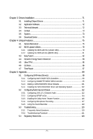
Box Contents GA-EX58-UD4P motherboard Motherboard driver disk User's Manual Quick Installation Guide One IDE cable Four SATA 3Gb/s cables One SATA bracket I/O shield 2-Way SLI bridge connector 3-Way SLI bridge connector • The box contents above are for reference only and the actual items shall - Gigabyte GA-EX58-UD4P | Manual - Page 7
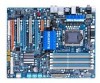
GA-EX58-UD4P Motherboard Layout KB_MS SYS_FAN3 R_SPDIF V1394 ATX_12V_2X CMOS_SW R_USB CPU Voltage L1/2/3 LGA1366 CPU TEMP L1/2 CPU_FAN PW_SW FREQ. LED PWR_FAN PHASE LED RST_SW USB ATX USB_LAN1 NB TEMP L1/2 AUDIO F_AUDIO PCIEX1_1 (Note) Intel® X58 RTL8111D PCIEX4_1 SPDIF_I - Gigabyte GA-EX58-UD4P | Manual - Page 8
(33 MHz) x1 LAN1 RJ45 RTL 8111D x1 PCI Express Bus 2 SATA 3Gb/s x1 GIGABYTE SATA2 ATA-133/100/66/33 IDE Channel PCI Bus TSB43AB23 QPI Interface Intel® X58 IOH CLK (133 MHz) Intel® ICH10R Dual BIOS 6 SATA 3Gb/s 12 USB Ports CODEC LPC Bus IT8720 Floppy PS/2 KB/Mouse 3 IEEE 1394a TPM - Gigabyte GA-EX58-UD4P | Manual - Page 9
or memory. If you do not have an ESD wrist strap, keep your hands dry and first touch a metal object to eliminate static electricity. • Prior to installing the motherboard, please have it on top of an antistatic pad or within an electrostatic shielding container. • Before unplugging the power supply - Gigabyte GA-EX58-UD4P | Manual - Page 10
QPI Chipset Memory Audio LAN Expansion Slots Storage Interface IEEE 1394 Support for an Intel® CoreTM i7 series processor in the LGA 1366 package (Go to GIGABYTE's website for the latest CPU support list.) L3 cache varies with CPU 4.8GT/s / 6.4GT/s North Bridge: Intel® X58 Express Chipset - Gigabyte GA-EX58-UD4P | Manual - Page 11
the back panel, 4 via the USB brackets connected to the internal USB headers) Internal Connectors 1 x 24-pin ATX main power connector 1 x 8-pin ATX 12V power connector 1 x floppy disk drive connector 1 x IDE connector 8 x SATA 3Gb/s connectors 1 x CPU fan header 3 x system fan - Gigabyte GA-EX58-UD4P | Manual - Page 12
graphics card, the PCIEX16_2 slot will operate at up to x8 mode. (Note 4) Whether the CPU/system fan speed control function is supported will depend on the CPU/ system cooler you install. (Note 5) Available functions in EasyTune may differ by motherboard model. GA-EX58-UD4P Motherboard - 12 - - Gigabyte GA-EX58-UD4P | Manual - Page 13
before you begin to install the CPU: • Make sure that the motherboard supports the CPU. (Go to GIGABYTE's website for the latest CPU support list.) • Always turn off the computer and unplug the power cord from the power outlet before installing the CPU to prevent hardware damage. • Locate the - Gigabyte GA-EX58-UD4P | Manual - Page 14
one corner of the CPU socket (or you may align the CPU notches with the socket alignment keys) and gently insert the CPU into position. Step 5: Once the CPU is properly inserted, replace the load plate and push the CPU socket lever back into its locked position. GA-EX58-UD4P Motherboard - 14 - - Gigabyte GA-EX58-UD4P | Manual - Page 15
installation manual for instructions on installing the cooler.) Step 5: After the installation, check the back of the motherboard. If the push pin is inserted as the picture above shows, the installation is complete. Step 6: Finally, attach the power connector of the CPU cooler to the CPU fan - Gigabyte GA-EX58-UD4P | Manual - Page 16
installed, a message which says memory is operating in Flex Memory Mode will appear during the POST. Intel® Flex Memory Technology offers greater flexibility to upgrade by allowing different memory sizes to be populated and remain in Dual/3 Channel mode/performance. GA-EX58-UD4P Motherboard - 16 - - Gigabyte GA-EX58-UD4P | Manual - Page 17
to turn off the computer and unplug the power cord from the power outlet to prevent damage to the memory module. DDR3 and DDR2 DIMMs are not compatible to each other or DDR DIMMs. Be sure to install DDR3 DIMMs on this motherboard. Notch DDR3 DIMM A DDR3 memory module has a notch, so it can only - Gigabyte GA-EX58-UD4P | Manual - Page 18
motherboard supports the expansion card. Carefully read the manual that came with your expansion card. • Always turn off the computer and unplug the power cord from the power BIOS Setup to make any required BIOS changes for your expansion card(s). 7. Install the driver GA-EX58-UD4P Motherboard - 18 - - Gigabyte GA-EX58-UD4P | Manual - Page 19
graphics cards! This section provides instructions on configuring an SLI/ CrossFireX system. A. Before You Begin 1. Power Requirements: Before installation, assure that the power supply you use is able to provide sufficient power to fully support an SLI/CrossFireX configuration and other components - Gigabyte GA-EX58-UD4P | Manual - Page 20
card Step 2: Connect power cables to the three graphics cards. Step 3: Plug the display cable into the graphics card on the PCIEX16_1 slot. (Note) To set up a 2-Way SLI system, insert the bridge into the SLI gold edge connectors on top of the two graphics cards. GA-EX58-UD4P Motherboard - 20 - - Gigabyte GA-EX58-UD4P | Manual - Page 21
SLI and Physx configuration screen. Ensure SLI configuration and Physx are enabled. C-2 To enable CrossFireX function For 2-Way CrossFireX: After installing graphics card driver Procedure for enabling SLI/CrossFireX technology may slightly differ by graphics cards. Refer to the manual that came with - Gigabyte GA-EX58-UD4P | Manual - Page 22
ends of the SATA signal cable and SATA power cable to your SATA device. For SATA device in external enclosure, you only need to connect the SATA signal cable. Before connecting the SATA signal cable, make sure to turn off the power of the external enclosure. GA-EX58-UD4P Motherboard - 22 - - Gigabyte GA-EX58-UD4P | Manual - Page 23
USB Port The USB port supports the USB 2.0/1.1 specification. Use this port for USB devices such as an USB keyboard/mouse, USB printer, USB flash drive and etc. RJ-45 LAN Port The Gigabit Ethernet from your device and then remove it from the motherboard. • When removing the cable, pull it straight - Gigabyte GA-EX58-UD4P | Manual - Page 24
to perform different functions via the audio software. Only microphones still MUST be connected to the default Mic in jack ( ). Refer to the instructions on setting up a 2/4/5.1/ 7.1-channel audio configuration in Chapter 5, "Configuring 2/4/5.1/7.1-Channel Audio." GA-EX58-UD4P Motherboard - 24 - - Gigabyte GA-EX58-UD4P | Manual - Page 25
1-9 Onboard LEDs and Switches Overvoltage LEDs This motherboard contains 4 sets of overvoltage LEDs which indicate the overvoltage level of the CPU, memory, North Bridge, and South Bridge. CPU (CPU Voltage) Off: Normal condition L1: Level 1 (Slight, green) L2: Level 2 (Moderate, yellow) L3: Level - Gigabyte GA-EX58-UD4P | Manual - Page 26
Quick Switches This motherboard has 3 quick switches: power switch, reset switch and clearing CMOS switch, allowing users to quickly turn on/off or reset the system or clear the CMOS values. PW_SW: Power switch RST_SW: Reset switch CMOS_SW: Clearing CMOS switch GA-EX58-UD4P Motherboard - 26 - - Gigabyte GA-EX58-UD4P | Manual - Page 27
with the connectors you wish to connect. • Before installing the devices, be sure to turn off the devices and your computer. Unplug the power cord from the power outlet to prevent damage to the devices. • After installing the device and before turning on the computer, make sure the device cable has - Gigabyte GA-EX58-UD4P | Manual - Page 28
+12V (Only for 2x4 pin 12V) 7 +12V 8 +12V 12 24 1 13 ATX GA-EX58-UD4P Motherboard ATX : Pin No. 1 2 3 4 5 6 7 8 9 10 11 12 Definition Pin No. 3.3V 13 3.3V 14 GND 15 +5V 16 GND 17 +5V 18 GND 19 Power Good 20 5V SB(stand by +5V) 21 +12V 22 +12V(Onlyfor2x12pin ATX) 23 - Gigabyte GA-EX58-UD4P | Manual - Page 29
fan cable, be sure to connect it in the correct orientation (the black connector wire is the ground wire). The motherboard supports CPU fan speed control, which requires the use of a CPU fan with fan speed control design. For optimum heat dissipation, it is recommended that a system fan be installed - Gigabyte GA-EX58-UD4P | Manual - Page 30
connect a floppy disk drive. The types of floppy disk drives supported are: 360 KB, 720 KB, 1.2 MB, 1.44 MB, and 2.88 MB. Before connecting a floppy disk drive, be sure to locate pin the IDE devices, read the instructions from the device manufacturers.) 39 1 40 2 GA-EX58-UD4P Motherboard - 30 - - Gigabyte GA-EX58-UD4P | Manual - Page 31
and are compatible with SATA 1.5Gb/s standard. Each SATA connector supports a single SATA device. The ICH10R controller supports RAID 0, RAID 1, RAID 5 and RAID 10. Refer to Chapter 5, "Configuring SATA Hard Drive(s)," for instructions on configuring a RAID array. SATA2_5 7 SATA2_3 SATA2_1 - Gigabyte GA-EX58-UD4P | Manual - Page 32
LED keeps blinking when the system is in S1 sleep state. The LED is off when the system is in S3/S4 sleep state or powered off (S5). 1 GA-EX58-UD4P Motherboard - 32 - Pin No. 1 2 3 Definition MPD+ MPDMPD- System Status LED S0 On S1 Blinking S3/S4/S5 Off - Gigabyte GA-EX58-UD4P | Manual - Page 33
negative pins before connecting the cables. Message/Power/ Power Sleep LED Switch Speaker MSG+ MSG- PW will be heard if no problem is detected at system startup. If a problem is detected, the BIOS may issue beeps in different patterns to indicate the problem. Refer to Chapter 5, "Troubleshooting - Gigabyte GA-EX58-UD4P | Manual - Page 34
supports HD audio by default. If your chassis provides an AC'97 front panel audio module, refer to the instructions on how to activate AC'97 functioninality via the audio software in Chapter 5, "Configuring 2/4/5.1/7.1-Channel Audio." • Audio signals will 4 CD-R GA-EX58-UD4P Motherboard - 34 - - Gigabyte GA-EX58-UD4P | Manual - Page 35
This header supports digital S/PDIF out and connects a S/PDIF digital audio cable (provided by expansion cards) for digital audio output from your motherboard to certain PDIF digital audio cable, carefully read the manual for your expansion card. Pin No. Definition 1 1 SPDIFO 2 GND - - Gigabyte GA-EX58-UD4P | Manual - Page 36
from the power outlet to prevent damage to the IEEE 1394a bracket. • To connect an IEEE 1394a device, attach one end of the device cable to your computer and then attach the other end of the cable to the IEEE 1394a device. Ensure that the cable is securely connected. GA-EX58-UD4P Motherboard - 36 - Gigabyte GA-EX58-UD4P | Manual - Page 37
turn off your computer and unplug the power cord from the power outlet before clearing the CMOS values. • motherboard. • After system restart, go to BIOS Setup to load factory defaults (select Load Optimized Defaults) or manually configure the BIOS settings (refer to Chapter 2, "BIOS Setup," for BIOS - Gigabyte GA-EX58-UD4P | Manual - Page 38
LEDs indicates the CPU loading. The higher the CPU loading, the more the number of lighted LEDs. To enable the Phase LED display function, please first enable Dynamic Energy Saver Advanced. Refer to Chapter 4, "Dynamic Energy Saver Advanced," for more details. GA-EX58-UD4P Motherboard - 38 - - Gigabyte GA-EX58-UD4P | Manual - Page 39
loading. The higher the North Bridge loading, the more the number of lighted LEDs. 24) DDR PHASE LED The number of lighted LEDs indicates the memory loading. The higher the memory loading, the more the number of lighted LEDs. - 39 - Hardware Installation - Gigabyte GA-EX58-UD4P | Manual - Page 40
GA-EX58-UD4P Motherboard - 40 - - Gigabyte GA-EX58-UD4P | Manual - Page 41
latest version of BIOS from the Internet and updates the BIOS. For instructions on using the Q-Flash and @BIOS utilities, refer to Chapter 4, "BIOS Update Utilities." • Because BIOS flashing is potentially risky, if you do not encounter problems using the current version of BIOS, it is recommended - Gigabyte GA-EX58-UD4P | Manual - Page 42
LOGO Screen (Default) B. The POST Screen Award Modular BIOS v6.00PG, An Energy Star Ally Copyright (C) 1984-2008, Award Software, Inc. Motherboard Model BIOS Version EX58-UD4P F1B . . . . Function Keys : BIOS Setup : XpressRecovery2 : Boot Menu : Qflash 11/17/2008-X58-ICH10 - Gigabyte GA-EX58-UD4P | Manual - Page 43
Setup Utility-Copyright (C) 1984-2008 Award Software MB Intelligent Tweaker(M.I.T.) Standard CMOS Features Advanced BIOS Features Integrated Peripherals Power Management Setup PC Health Status Load Fail-Safe Defaults Load Optimized Defaults Set Supervisor Password Set User Password - Gigabyte GA-EX58-UD4P | Manual - Page 44
Without Saving Abandon all changes and the previous settings remain in effect. Pressing to the confirmation message will exit BIOS Setup. (Pressing can also carry out this task.) Security Chip Configuration Use this menu to configure the TPM function. GA-EX58-UD4P Motherboard - 44 - - Gigabyte GA-EX58-UD4P | Manual - Page 45
F1: General Help F7: Optimized Defaults Whether the system will work stably with the overclock/overvoltage settings you made is dependent on your overall system configurations. Incorrectly doing overclock/overvoltage may result in damage to CPU, chipset, or memory and reduce the useful life of - Gigabyte GA-EX58-UD4P | Manual - Page 46
power consumption. The C3/C6/C7 state is a more enhanced power-saving state than C1. (Default: Disabled) (Note) This item is present only if you install a CPU that supports this feature. For more information about Intel CPUs' unique features, please visit Intel's website. GA-EX58-UD4P Motherboard - Gigabyte GA-EX58-UD4P | Manual - Page 47
will be reduced when the CPU is overheated. (Default: Enabled) CPU EIST Function (Note) Enables or disables Enhanced Intel SpeedStep Technology (EIST). Depending on CPU loading, Intel® EIST technology can dynamically and effectively lower the CPU voltage and core frequency to decrease average power - Gigabyte GA-EX58-UD4P | Manual - Page 48
% or 19% depending on CPU loading. Warning: Before using C.I.A.2, please first verify the overclocking capability of your CPU. As stability is highly dependent on system components, when system instability occurs after overclocking, lower the overclocking ratio. GA-EX58-UD4P Motherboard - 48 - - Gigabyte GA-EX58-UD4P | Manual - Page 49
(X.M.P.)(Note) Allows the BIOS to read the SPD data on XMP memory module(s) to enhance memory performance when enabled. Disabled Disables this function. (Default) Profile1 Uses Profile 1 settings. (Note) This item appears only if you install a memory module that supports this feature. - 49 - Gigabyte GA-EX58-UD4P | Manual - Page 50
>>>>> Channel A/B/C Standard Timing Control CAS Latency Time Options are: Auto (default), 6~16. tRCD Options are: Auto (default), 1~15. tRP Options are: Auto (default), 1~15. tRAS Options are: Auto (default), 1~63. GA-EX58-UD4P Motherboard - 50 - ESC: Exit F1: General Help F7: Optimized - Gigabyte GA-EX58-UD4P | Manual - Page 51
Channel A/B/C Misc Timing Control Round Trip Latency Options are: Auto (default), 1~255. >>>>> Channel A/B/C Turnaround Settings CMOS Setup Utility-Copyright (C) 1984-2008 Award Software Channel A Turnaround Settings >>>>> Channel A Writes Followed by Reads x Different DIMMs 6 x Different - Gigabyte GA-EX58-UD4P | Manual - Page 52
Auto (default), 1~8. On The Same Rank Options are: Auto (default), 1~2. >>>>> Channel A/B/C Writes Followed by Writes Different DIMMs Options are: Auto (default), 1~8. Different Ranks Options are: Auto (default), 1~8. On The Same Rank Options are: Auto (default), 1~2. GA-EX58-UD4P Motherboard - 52 - Gigabyte GA-EX58-UD4P | Manual - Page 53
this feature adjusts Vdroop, keeping the CPU voltage more constant under light and heavy CPU load. Disabled sets the CPU voltage following Intel specifications. (Default: Disabled) CPU Vcore The default is Auto. QPI/Vtt Voltage The default is Auto. CPU PLL The default is Auto. - 53 - BIOS Setup - Gigabyte GA-EX58-UD4P | Manual - Page 54
DRAM Termination The default is Auto. Ch-A Data VRef. The default is Auto. Ch-B Data VRef. The default is Auto. Ch-C Data VRef. The default is Auto. Ch-A Address VRef. The default is Auto. Ch-B Address VRef. The default is Auto. Ch-C Address VRef. The default is Auto. GA-EX58-UD4P Motherboard - 54 - Gigabyte GA-EX58-UD4P | Manual - Page 55
Default ESC: Exit F1: General Help F7: Optimized Defaults Base Memory Extended Memory Total Memory CMOS Setup Utility-Copyright (C) 1984-2008 Award Software of the IDE/SATA device on this channel. IDE Channel 0/1 Master/Slave Configure your IDE/SATA devices by using one of the three - Gigabyte GA-EX58-UD4P | Manual - Page 56
only and are determined by the BIOS POST. Base Memory Also called conventional memory. Typically, 640 KB will be reserved for the MS-DOS operating system. Extended Memory The amount of extended memory. Total Memory The total amount of memory installed on the system. GA-EX58-UD4P Motherboard - 56 - - Gigabyte GA-EX58-UD4P | Manual - Page 57
-2008 Award Software Advanced BIOS Features Hard Disk Boot Priority First Boot Device [Press Enter] [Floppy] Item Help Menu Level Second Boot Device Third Boot Device Password Check [Hard Disk] [CDROM] [Setup] HDD S.M.A.R.T. Capability Limit CPUID Max. to 3 (Note) No-Execute Memory Protect - Gigabyte GA-EX58-UD4P | Manual - Page 58
. Sets PCI Express graphics card on the PCI Express x4 slot (PCIEX4_1) as the first display. (Note) This item is present only if you install a CPU that supports this feature. For more information about Intel CPUs' unique features, please visit Intel's website. GA-EX58-UD4P Motherboard - 58 - - Gigabyte GA-EX58-UD4P | Manual - Page 59
Award Software Integrated Peripherals SATA RAID/AHCI Mode SATA Port0-3 Native Mode USB 1.0 Controller USB 2.0 Controller USB Keyboard Function USB Mouse Function USB Storage Function Azalia Codec Onboard H/W 1394 Onboard H/W LAN Green LAN SMART LAN Onboard LAN Boot ROM Onboard SATA/IDE Device - Gigabyte GA-EX58-UD4P | Manual - Page 60
the figure above. When LAN Cable Is Functioning Normally... If no cable problem is detected on the LAN cable connected to a Gigabit hub or a 10/100 Mbps hub, the following message will appear: Start detecting at Port..... Link Detected --> 100Mbps Cable Length= 30m GA-EX58-UD4P Motherboard - 60 - - Gigabyte GA-EX58-UD4P | Manual - Page 61
boot ROM integrated with the onboard LAN chip. (Default: Disabled) Onboard SATA/IDE Device (GIGABYTE SATA2 Chip) Enables or disables the IDE and SATA controllers integrated in the GIGABYTE SATA2 chip. (Default: Enabled) Onboard SATA/IDE Ctrl Mode (GIGABYTE SATA2 Chip) Enables or disables RAID - Gigabyte GA-EX58-UD4P | Manual - Page 62
1A on the +5VSB lead. (Default: Enabled) Power On by Ring Allows the system to be awakened from an ACPI sleep state by a wake-up signal from a modem that supports wake-up function. (Default: Enabled) (Note) Supported on Windows® Vista® operating system only. GA-EX58-UD4P Motherboard - 62 - - Gigabyte GA-EX58-UD4P | Manual - Page 63
need an ATX power supply providing at least 1A on the +5VSB lead. Disabled Disables this function. (Default) Double Click power from an AC power loss. Soft-Off The system stays off upon the return of the AC power. (Default) Full-On Memory The system is turned on upon the return of the AC power - Gigabyte GA-EX58-UD4P | Manual - Page 64
(default), 60oC/140oF, 70oC/158oF, 80oC/ 176oF, 90oC/194oF. CPU/SYSTEM/POWER FAN Fail Warning Allows the system to emit warning sound if the CPU/system/power fan is not connected or fails. Check the fan condition or fan connection when this occurs. (Default: Disabled) GA-EX58-UD4P Motherboard - Gigabyte GA-EX58-UD4P | Manual - Page 65
on system requirements. If disabled, CPU fan runs at full speed. (Default: Enabled) CPU Smart FAN Mode Specifies how to control CPU fan speed. This item is configurable only if CPU Smart FAN Control is set to Enabled. Auto Lets BIOS autodetect the type of CPU fan installed and sets the optimal - Gigabyte GA-EX58-UD4P | Manual - Page 66
Defaults Press on this item and then press the key to load the optimal BIOS default settings. The BIOS defaults settings helps the system to operate in optimum state. Always load the Optimized defaults after updating the BIOS or after clearing the CMOS values. GA-EX58-UD4P Motherboard - Gigabyte GA-EX58-UD4P | Manual - Page 67
Utility-Copyright (C) 1984-2008 Award Software MB Intelligent Tweaker(M.I.T.) Standard CMOS Features Advanced BIOS Features Integrated Peripherals Power Management SEentutepr Password: PC Health Status Load Fail-Safe Defaults Load Optimized Defaults Set Supervisor Password Set User - Gigabyte GA-EX58-UD4P | Manual - Page 68
Setup F11: Save CMOS to BIOS F12: Load CMOS from BIOS Abandon all Data Press on this item and press the key. This exits the BIOS Setup without saving the changes made in BIOS Setup to the CMOS. Press or to return to the BIOS Setup Main Menu. GA-EX58-UD4P Motherboard - 68 - - Gigabyte GA-EX58-UD4P | Manual - Page 69
Software Security Chip Configuration [Disabled] Item Help Menu Level Security Chip State Disabled/Deactivated Move Enter: Select F5: Previous Values +/-/PU/PD: Value F10: Save F6: Fail-Safe Defaults ESC: Exit F1: General Help F7: Optimized Defaults Security Default) Security Chip - Gigabyte GA-EX58-UD4P | Manual - Page 70
GA-EX58-UD4P Motherboard - 70 - - Gigabyte GA-EX58-UD4P | Manual - Page 71
system restart, "Xpress Install" will continue to install other drivers. • After the drivers are installed, follow the onscreen instructions to restart your system. You can install other applications included in the motherboard driver disk. • For USB 2.0 driver support under the Windows XP operating - Gigabyte GA-EX58-UD4P | Manual - Page 72
that GIGABYTE develops and some free software. You can click the Install button on the right of an item to install it. 3-3 Technical Manuals This page provides GIGABYTE's application guides, content descriptions for this driver disk, and the motherboard manuals. GA-EX58-UD4P Motherboard - 72 - Gigabyte GA-EX58-UD4P | Manual - Page 73
3-4 Contact For the detailed contact information of the GIGABYTE Taiwan headquarter or worldwide branch offices, click the URL on this page to link to the GIGABYTE Website. 3-5 System This page provides the basic system information. - 73 - Drivers Installation - Gigabyte GA-EX58-UD4P | Manual - Page 74
3-6 Download Center To update the BIOS, drivers, or applications, click the Download Center button to link to the GIGABYTE Web site. The latest version of the BIOS, drivers, or applications will be displayed. GA-EX58-UD4P Motherboard - 74 - - Gigabyte GA-EX58-UD4P | Manual - Page 75
created with Xpress Recovery cannot be restored using Xpress Recovery2. • USB hard drives are not supported. • Hard drives in RAID/AHCI mode are not supported. Installation and Configuration Turn on your system to boot from the Windows Vista setup disk. A. Installing Windows Vista and Partitioning - Gigabyte GA-EX58-UD4P | Manual - Page 76
Backup Function in Xpress Recovery2 Xpress Recovery2 will automatically create a new partition to store the backup image file. Step 1: Select BACKUP to start backing up your hard drive data. Step 2: When finished, go to Disk Management to check disk allocation. GA-EX58-UD4P Motherboard - 76 - - Gigabyte GA-EX58-UD4P | Manual - Page 77
the Restore Function in Xpress Recovery2 Select RESTORE to restore the backup to your hard drive in case the system breaks down. The RESTORE option will not be present if no backup is created before. E. Removing the Backup Step 1: If you wish to remove the backup file, select REMOVE. F. Exiting - Gigabyte GA-EX58-UD4P | Manual - Page 78
Software, Inc. EX58-UD4P F1B . . . . : BIOS Setup : XpressRecovery2 : Boot Menu : Qflash 11/17/2008-X58-ICH10-7A89QG08C-00 Because BIOS flashing is potentially risky, please do it with caution. Inadequate BIOS flashing may result in system malfunction. GA-EX58-UD4P Motherboard - Gigabyte GA-EX58-UD4P | Manual - Page 79
option allows you to save the current BIOS file. • Q-Flash only supports USB flash drive or hard drives using FAT32/16/12 file system. • If the BIOS update file is saved to a hard drive in RAID/AHCI mode or a hard drive attached to an independent IDE/SATA controller, use the key during the - Gigabyte GA-EX58-UD4P | Manual - Page 80
Setup F11: Save CMOS to BIOS F12: Load CMOS from BIOS Load Optimized Defaults Press to load BIOS defaults Step 6: Select Save & Exit Setup and then press to save settings to CMOS and exit BIOS Setup. The procedure is complete after the system restarts. GA-EX58-UD4P Motherboard - 80 - - Gigabyte GA-EX58-UD4P | Manual - Page 81
matches your motherboard model. Follow the onscreen instructions to complete. If the BIOS update file for your motherboard is not present on the @BIOS server site, please manually download the BIOS update file from GIGABYTE's website and follow the instruc- tions in "Update the BIOS without Using - Gigabyte GA-EX58-UD4P | Manual - Page 82
the hardware components such as CPU, chipset, and memory and reduce the useful life of these components. Before you do the overclock/overvoltage, make sure that you fully know each function of EasyTune 6, or system instability or other unexpected results may occur. GA-EX58-UD4P Motherboard - 82 - - Gigabyte GA-EX58-UD4P | Manual - Page 83
Mode, GIGABYTE Dynamic Energy Saver Advanced shows how much power they have saved in a set period of time. Meter Mode - Button Information Table Button Description 1 Dynamic Energy Saver On/Off Switch (Default: Off) 2 Motherboard Phase LED On/Off Switch (Default: On) 3 Dynamic CPU Frequency - Gigabyte GA-EX58-UD4P | Manual - Page 84
power saved will be recorded until re-activated when only the Dynamic Power Saver is under the enable status, and power savings meter is unable to reset to zero. (Note 5) Dynamic Energy Saver Meter will automatically reset when the total power saving reaches 99999999 Watts. GA-EX58-UD4P Motherboard - Gigabyte GA-EX58-UD4P | Manual - Page 85
to Chapter 2, "BIOS Setup," for more information.) Save changes and then restart your computer. Encrypted files will become inaccessible after the TPM chip is cleared. Be sure to back up the encrypted files first. Step 2: Install the Infineon TPM driver from the motherboard driver disk (select - Gigabyte GA-EX58-UD4P | Manual - Page 86
Share After installing Q-Share from the motherboard driver disk, go to Start>All Programs>GIGABYTE> Q-Share.exe to launch the Q- Updates Q-Share online Displays the current Q-Share version Exits Q-Share (Note) This option is available only when data sharing is NOT enabled. GA-EX58-UD4P Motherboard - Gigabyte GA-EX58-UD4P | Manual - Page 87
Based on the Microsoft Volume Shadow Copy Services technology, Time Repair allows you to quickly back up and restore your system data in the Windows Vista operating system. Time Repair supports NTFS file system and can restore system data on PATA and SATA hard drives. System Restore Choose a system - Gigabyte GA-EX58-UD4P | Manual - Page 88
GA-EX58-UD4P Motherboard - 88 - - Gigabyte GA-EX58-UD4P | Manual - Page 89
for the SATA port. (For example, on this motherboard, the SATA2_0, SATA2_1, SATA2_2, SATA2_3, SATA2_4 and SATA2_5 ports are supported by ICH10R Southbridge.) Then connect the power connector from your power supply to the hard drive. (Note 1) Skip this step if you do not want to create RAID array on - Gigabyte GA-EX58-UD4P | Manual - Page 90
Defaults Step 2: Save changes and exit BIOS Setup. The BIOS Setup menus described in this section may differ from the exact settings for your motherboard. The actual BIOS Setup menu options you will see shall depend on the motherboard you have and the BIOS version. GA-EX58-UD4P Motherboard - Gigabyte GA-EX58-UD4P | Manual - Page 91
C. Configuring a RAID array in RAID BIOS Enter the RAID BIOS setup utility to configure a RAID array. Skip this step and proceed with the installation of Windows operating system for a non-RAID configuration. Step 1: After the POST memory test begins and before the operating system boot begins, - Gigabyte GA-EX58-UD4P | Manual - Page 92
: RAID Level : Disks : Strip Size : Capacity : Volume0 RAID0(Stripe) Select Disks 128KB 223.6 GB Create Volume [ HELP ] The following are typical values: RAID0 - 128KB RAID10 - 64KB RAID5 - 64KB [ ]-Change [TAB]-Next [ESC]-Previous Menu Figure 5 [ENTER]-Select GA-EX58-UD4P Motherboard - Gigabyte GA-EX58-UD4P | Manual - Page 93
.8GB Member Disk(0) []-Select [ESC]-Exit Figure 7 [ENTER]-Select Menu To exit the ICH10R RAID BIOS utility, press or select Exit in MAIN MENU. Now, you can proceed to create the SATA RAID/AHCI driver diskette and install the SATA RAID/ACHI driver and operating system. - 93 - Appendix - Gigabyte GA-EX58-UD4P | Manual - Page 94
] ALL DATA IN THE[VHOELLUPM] E WILL BE LOST! Are you sure you want to delete "Volume0"? (Y/N) : Deleting a volume will reset the disks to non-RAID. WARNING: ALL DISK DATA WILL BE DELETED. [ ]-Select [ESC]-Previous Menu Figure 8 [DEL]-Delete Volume GA-EX58-UD4P Motherboard - 94 - - Gigabyte GA-EX58-UD4P | Manual - Page 95
the SATA controller for the SATA port. (For example, on this motherboard, the GSATA2_0 and GSATA2_1 ports are supported by GIGABYTE SATA2.) Then connect the power connector from your power supply to the hard drive. B. Configuring SATA controller mode and device boot order in BIOS Setup Make - Gigabyte GA-EX58-UD4P | Manual - Page 96
[ RAID Disk Drive List ] [TAB]-Switch Window []-Select ITEM [ENTER]-Action Figure 3 [ESC]-Exit Note: In the main screen, you can select a hard drive in the Hard Disk Drive List block and press to see detailed information about the selected hard drive. GA-EX58-UD4P Motherboard - Gigabyte GA-EX58-UD4P | Manual - Page 97
In the main screen, press on the Create RAID Disk Drive item. Then the Create New RAID screen appears (Figure 4). GIGABYTE Technology Corp. PCIE-to-SATAII/IDE RAID Controller BIOS v1.06.78 [ Create New RAID ] [ Hard Disk Drive List ] Name: GRAID_ Level: 0-Stripe Disks: Select Disk Block - Gigabyte GA-EX58-UD4P | Manual - Page 98
Non-RAID Confirm Creation [ RAID Disk Drive List ] [ Help ] Create RAID on the select HDD(Y/N)?Y CONFIRM RAID CREATION ALL DATA ON THE SELECTED HARD DISK WILL BE LOST WHEN EXIT WITH SAVING []-Switch Unit [DEL,BS]-Delete Number Figure 7 [ENTER]-Next [ESC]-Abort GA-EX58-UD4P Motherboard - Gigabyte GA-EX58-UD4P | Manual - Page 99
, the new RAID array will be displayed in the RAID Disk Drive List block (Figure 8). GIGABYTE Technology Corp. PCIE-to-SATAII/IDE RAID Controller BIOS v1.06.78 [ Main Menu ] [ Hard Disk Drive List ] Create RAID Disk Drive Delete RAID Disk Drive Revert HDD to Non-RAID Solve Mirror Conflict - Gigabyte GA-EX58-UD4P | Manual - Page 100
Inside RAID Inside [ RAID Disk Drive List ] Model Name RDD0: GRAID ALL DATA ON THE RAID WILL LOST!! ARE YOU SURE TO DELETE (Y/N)? N RAID Level Capacity Status 0-Stripe 240 GB Normal Members(HDDx) 01 []-Select RAID [SPACE]-Mark Delete [DEL]-Confirm Figure 11 GA-EX58-UD4P Motherboard - Gigabyte GA-EX58-UD4P | Manual - Page 101
to a floppy disk. See the instructions below about how to copy the driver in MS-DOS mode(Note). Prepare a startup disk that has CD-ROM support and a blank formatted floppy disk. Step 1: Insert the prepared startup disk and motherboard driver disk in your system. Boot from the startup disk. Once at - Gigabyte GA-EX58-UD4P | Manual - Page 102
the following list, or press ESC to return to the previous screen. Intel(R) ICH7R/DH SATA RAID Controller Intel(R) ICH7MDH SATA RAID Controller Intel(R) ICH8R/ICH9R/ICH10R/DO SATA RAID Controller Intel(R) ICH8M-E/ICH9M-E SATA RAID Controller ENTER=Select F3=Exit Figure 2 GA-EX58-UD4P Motherboard - Gigabyte GA-EX58-UD4P | Manual - Page 103
the SATA RAID/AHCI driver and press . Then a controller menu similar to Figure 3 below will appear. Select (Windows XP/2003) RAID/AHCI Driver for GIGABYTE GBB36X Controller and press . Windows Setup You have chosen to configure a SCSI Adapter for use with Windows, using a device support - Gigabyte GA-EX58-UD4P | Manual - Page 104
following directory: \BootDrv\iMSM\32Bit For Windows Vista 64-bit, browse to the 64Bit folder. Method B: Insert the USB flash drive containing the driver files and browse to \iMSM\32Bit (for Windows Vista 32bit) or \iMSM\64Bit (for Windows Vista 64-bit). GA-EX58-UD4P Motherboard Figure 5 - 104 - - Gigabyte GA-EX58-UD4P | Manual - Page 105
Step 3: When a screen as shown in Figure 6 appears, select Intel(R) ICH8R/ICH9R/ICH10R/DO SATA RAID Controller and click Next. Figure 6 Step 4: After the driver is loaded, select the RAID/AHCI drive(s) where you want to install the operating system and then click Next to continue the OS - Gigabyte GA-EX58-UD4P | Manual - Page 106
directory: \BootDrv\GSATA\32Bit For Windows Vista 64-bit, browse to the 64Bit folder. Method B: Insert the USB flash drive containing the driver files and browse to \GSATA\32Bit (for Windows Vista 32-bit) or \GSATA\64Bit (for Windows Vista 64-bit). GA-EX58-UD4P Motherboard Figure 9 - 106 - - Gigabyte GA-EX58-UD4P | Manual - Page 107
Step 3: When a screen as shown in Figure 10 appears, select GIGABYTE GBB36X Controller and press Next. Figure 10 Step 4: After the driver is loaded, select the RAID/AHCI drive(s) where you want to install the operating system and then press Next to continue the OS installation (Figure 11). Figure - Gigabyte GA-EX58-UD4P | Manual - Page 108
drive to rebuild a RAID 1 array. (Note: The new drive must have equal or greater capacity than the old one.) Intel® ICH10R SATA controller: Turn off your "Rebuild" status will be rebuilt within the operating system. []-Select [ESC]-Exit [ENTER]-Select Menu GA-EX58-UD4P Motherboard - 108 - - Gigabyte GA-EX58-UD4P | Manual - Page 109
chipset driver has been installed from the motherboard driver disk. Then launch the Intel® Matrix Storage Console from All Programs in the Start menu. Step 1: On the View menu of the Intel Click Next when the Rebuild RAID Volume Wizard appears. Follow the on-screen instructions to proceed. Step 4: - Gigabyte GA-EX58-UD4P | Manual - Page 110
Model Name HDD0: ST3120026AS HDD1: ST3120026AS Capacity Type/Status 120 GB RAID Inside 120 GB Non-RAID [ RAID Disk Drive List ] Model Name RDD0: GRAID RAID Level 1-Mirror Capacity Status Members(HDDx) 120 GB Degraded 0? Rebuilding....35%, please wait.... GA-EX58-UD4P Motherboard - 110 - - Gigabyte GA-EX58-UD4P | Manual - Page 111
Make sure the GIGABYTE SATA2 SATA controller driver has been installed from the motherboard driver disk. Launch the GIGABYTE RAID CONFIGURER from All Programs in the Start menu. Step 1: In the GIGABYTE RAID CONFIGUERE screen, right-click on the array to be rebuilt in the RAID LIST block. Select - Gigabyte GA-EX58-UD4P | Manual - Page 112
out, Rear speaker out, and Center/Subwoofer speaker out. • 7.1-channel audio: Front speaker out, Rear speaker out, Center/Subwoofer speaker out, and Side speaker out. GA-EX58-UD4P Motherboard - 112 - - Gigabyte GA-EX58-UD4P | Manual - Page 113
the type of device you connect. Then click OK. Step 3: On the Speakers screen, click the Speaker Configuration tab. In the Speaker Configuration list, select Stereo, Quadraphonic, 5.1 Speaker, or 7.1 Speaker according to the type of speaker configuration you wish to set up. Then the speaker setup is - Gigabyte GA-EX58-UD4P | Manual - Page 114
the chassis back panel with a screw. 2. Configuring S/PDIF In: On the Digital Input screen, click the Default Format tab to select the default format. Click OK to complete. (Note) The actual locations of the SPDIF In and SPDIF Out connectors may differ by model. GA-EX58-UD4P Motherboard - 114 - - Gigabyte GA-EX58-UD4P | Manual - Page 115
optical cable (either one) to an external decoder for transmitting the S/PDIF digital audio signals. 2. Configuring S/PDIF Out: On the Digital Output screen, click the Default Format tab and then select the sample rate and bit depth. Click OK to complete. - 115 - Appendix - Gigabyte GA-EX58-UD4P | Manual - Page 116
will be transformed into multi-channel audio, creating a virtual surround sound environment . (Note) Install the Dolby GUI Software driver from the motherboard driver output (S/PDIF) is working, and you will not hear any sound from analog speakers or headphone. GA-EX58-UD4P Motherboard - 116 - - Gigabyte GA-EX58-UD4P | Manual - Page 117
5-2-4 Configuring Microphone Recording Step 1: After installing the audio driver, the HD Audio Manager icon will appear in the notification area. Doubleclick the icon to access the . If you want to change the current sound input default device to microphone, right-click on Microphone and select Set - Gigabyte GA-EX58-UD4P | Manual - Page 118
and right-click on this icon. Select Recording Devices. Step 2: On the Recording tab, right-click on an empty space and select Show Disabled Devices. GA-EX58-UD4P Motherboard - 118 - - Gigabyte GA-EX58-UD4P | Manual - Page 119
Mix item appears, right-click on this item and select Enable. Then set it as the default device. Step 4: Now you can access the HD Audio Manager to configure Stereo Mix and use : You can play your recording in a digital media player program that supports your audio file format. - 119 - Appendix - Gigabyte GA-EX58-UD4P | Manual - Page 120
setting error 1 long, 1 short: Memory or motherboard error 1 long, 2 short: Monitor or graphics card error 1 long, 3 short: Keyboard error 1 long, 9 short: BIOS ROM error Continuous long beeps: Graphics card not inserted properly Continuous short beeps: Power error GA-EX58-UD4P Motherboard - 120 - - Gigabyte GA-EX58-UD4P | Manual - Page 121
cooler on the CPU. Connect the CPU cooler power cable to the motherboard. The problem is verified and solved. No Correctly insert the memory into the memory socket. The problem is verified and solved. Press to enter BIOS Setup. Select "Load Fail-Safe Defaults" (or "Load Optimized - Gigabyte GA-EX58-UD4P | Manual - Page 122
solved. END If the procedure above is unable to solve your problem, contact the place of purchase or local dealer for help. Or go to the Support\Technical Service Zone page to submit your question. Our customer service staff will reply you as soon as possible. GA-EX58-UD4P Motherboard - 122 - - Gigabyte GA-EX58-UD4P | Manual - Page 123
GIGABYTE. Our Commitment to Preserving the Environment In addition to high-efficiency performance, all GIGABYTE motherboards office, your household waste disposal service or where you purchased the product Care number listed in your product's user's manual and we will be glad to help you with - Gigabyte GA-EX58-UD4P | Manual - Page 124
hazardous substances are not released into the environment and are disposed of properly. China Restriction of Hazardous Substances Table The following table is supplied in compliance with China's Restriction of Hazardous Substances (China RoHS) requirements: GA-EX58-UD4P Motherboard - 124 - - Gigabyte GA-EX58-UD4P | Manual - Page 125
- 125 - Appendix - Gigabyte GA-EX58-UD4P | Manual - Page 126
GA-EX58-UD4P Motherboard - 126 - - Gigabyte GA-EX58-UD4P | Manual - Page 127
231, Taiwan TEL: +886-2-8912-4000 FAX: +886-2-8912-4003 Tech. and Non-Tech. Support (Sales/Marketing) : http://ggts.gigabyte.com.tw WEB address (English): http://www.gigabyte.com.tw WEB address (Chinese): http://www.gigabyte.tw G.B.T. INC. - U.S.A. TEL: +1-626-854-9338 FAX: +1-626-854-9339 Tech - Gigabyte GA-EX58-UD4P | Manual - Page 128
language in the language list on the top right corner of the website. GIGABYTE Global Service System To submit a technical or non-technical (Sales/ Marketing) question, please link to : http://ggts.gigabyte.com.tw Then select your language to enter the system. GA-EX58-UD4P Motherboard - 128 -
-
 1
1 -
 2
2 -
 3
3 -
 4
4 -
 5
5 -
 6
6 -
 7
7 -
8
-
9
-
10
-
11
-
12
-
13
-
14
-
15
-
16
-
17
-
18
-
19
-
20
-
21
-
22
-
23
-
24
-
25
-
26
-
27
-
28
-
29
-
30
-
31
-
32
-
33
-
34
-
35
-
36
-
37
-
38
-
39
-
40
-
41
-
42
-
43
-
44
-
45
-
46
-
47
-
48
-
49
-
50
-
51
-
52
-
53
-
54
-
55
-
56
-
57
-
58
-
59
-
60
-
61
-
62
-
63
-
64
-
65
-
66
-
67
-
68
-
69
-
70
-
71
-
72
-
73
-
74
-
75
-
76
-
77
-
78
-
79
-
80
-
81
-
82
-
83
-
84
-
85
-
86
-
87
-
88
-
89
-
90
-
91
-
92
-
93
-
94
-
95
-
96
-
97
-
98
-
99
-
100
-
101
-
102
-
103
-
104
-
105
-
106
-
107
-
108
-
109
-
110
-
111
-
112
-
113
-
114
-
115
-
116
-
117
-
118
-
119
-
120
-
121
-
122
-
123
-
124
-
125
-
126
-
127
-
128
 |
 |

GA-EX58-UD4P
LGA1366 socket motherboard for Intel
®
Core
TM
i7 processor family
User's Manual
Rev. 1004
12ME-EX58UD4-1004R