Gigabyte GA-EX58-UD5 Manual
Gigabyte GA-EX58-UD5 Manual
 |
UPC - 818313006837
View all Gigabyte GA-EX58-UD5 manuals
Add to My Manuals
Save this manual to your list of manuals |
Gigabyte GA-EX58-UD5 manual content summary:
- Gigabyte GA-EX58-UD5 | Manual - Page 1
GA-EX58-UD5P/ GA-EX58-UD5 LGA1366 socket motherboard for Intel® CoreTM i7 processor family User's Manual Rev. 1005 12ME-EX58UD5-1005R - Gigabyte GA-EX58-UD5 | Manual - Page 2
Motherboard GA-EX58-UD5P/GA-EX58-UD5 Oct. 31, 2008 Motherboard GA-EX58-UD5P/ GA-EX58-UD5 Oct. 31, 2008 - Gigabyte GA-EX58-UD5 | Manual - Page 3
set-up of the product, read the Quick Installation Guide included with the product. For detailed product information, carefully read the User's Manual. For instructions on how to use GIGABYTE's unique features, read or download the information on/from the Support\Motherboard\Technology Guide - Gigabyte GA-EX58-UD5 | Manual - Page 4
...6 GA-EX58-UD5P/GA-EX58-UD5 Motherboard Layout 7 Block Diagram...8 Chapter 1 Hardware Installation 9 1-1 Installation Precautions 9 1-2 Product Specifications 10 1-3 Installing the CPU and CPU Cooler 13 1-3-1 Installing the CPU 13 1-3-2 Installing the CPU Cooler 15 1-4 Installing the Memory - Gigabyte GA-EX58-UD5 | Manual - Page 5
Chipset Drivers 73 3-2 Application Software 74 3-3 Technical Manuals 74 3-4 Contact ...75 3-5 System ...75 3-6 Download Center 76 Chapter 4 Unique Features 77 4-1 Xpress Recovery2 77 4-2 BIOS Update Utilities 80 4-2-1 Updating the BIOS with the Q-Flash Utility 80 4-2-2 Updating the BIOS - Gigabyte GA-EX58-UD5 | Manual - Page 6
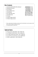
Box Contents GA-EX58-UD5P/GA-EX58-UD5 motherboard Motherboard driver disk User's Manual Quick Installation Guide One IDE cable Four SATA you obtain. The box contents are subject to change without notice. • The motherboard image is for reference only. Optional Items Floppy disk drive cable (Part No. - Gigabyte GA-EX58-UD5 | Manual - Page 7
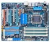
PW_SW FREQ. LED PWR_FAN PHASE LED RST_SW USB_LAN2 ATX USB_LAN1 DDR Voltage LED DDR PHASE LED SPDIF_O CD_IN NB TEMP L1/2 AUDIO F_AUDIO PCIEX1_1 (Note 1) RTL8111D Intel® X58 RTL8111D PCIEX4_1 SPDIF_I CODEC NB_FAN NB Voltage L1/2/3 PCIEX16_1 PCI1 GA-EX58-UD5P/GA-EX58-UD5 PCIEX16_2 - Gigabyte GA-EX58-UD5 | Manual - Page 8
X58 IOH CLK (133 MHz) Intel® ICH10R Dual BIOS 6 SATA 3Gb/s 12 USB Ports CODEC LPC Bus IT8720 Floppy PS/2 KB/Mouse 3 IEEE 1394a TPM* Surround Speaker Out Center/Subwoofer Speaker Out Side Speaker Out MIC Line-Out Line-In SPDIF In SPDIF Out 2 PCI PCI CLK (33 MHz) "*" Only for GA-EX58-UD5P - Gigabyte GA-EX58-UD5 | Manual - Page 9
manual and follow these procedures: • Prior to installation, do not remove or break motherboard electronic components such as a motherboard, CPU or memory. If you do not have system components as well as physical harm to the user. • If you are uncertain about any installation steps or have a problem - Gigabyte GA-EX58-UD5 | Manual - Page 10
CoreTM i7 series processor in the LGA 1366 package (Go to GIGABYTE's website for the latest CPU support list.) L3 cache varies with CPU 4.8GT/s / 6.4GT/s North Bridge: Intel® X58 Express Chipset South Bridge: Intel® ICH10R 6 x 1.5V DDR3 DIMM sockets supporting up to 2 4 GB of system memory - Gigabyte GA-EX58-UD5 | Manual - Page 11
connector 1 x 8-pin ATX 12V power connector 1 x floppy disk drive connector 1 x IDE connector 10 x SATA 3Gb/s connectors 1 x CPU fan header 3 x system fan headers 1 x power fan header 1 x North Bridge fan header 1 x front panel header 1 x front panel audio header 1 x CD In - Gigabyte GA-EX58-UD5 | Manual - Page 12
to enable the Smart Backup function.) (Note 5) Whether the CPU/system fan speed control function is supported will depend on the CPU/ system cooler you install. (Note 6) Available functions in EasyTune may differ by motherboard model. "*" Only for GA-EX58-UD5P. GA-EX58-UD5P/UD5 Motherboard - 12 - - Gigabyte GA-EX58-UD5 | Manual - Page 13
the CPU: • Make sure that the motherboard supports the CPU. (Go to GIGABYTE's website for the latest CPU support list.) • Always turn off the computer • Set the CPU host frequency in accordance with the CPU specifications. It is not recom- mended that the system bus frequency be set beyond - Gigabyte GA-EX58-UD5 | Manual - Page 14
B. Follow the steps below to correctly install the CPU into the motherboard CPU socket. Before installing the CPU, make sure to turn off the computer and unplug properly inserted, replace the load plate and push the CPU socket lever back into its locked position. GA-EX58-UD5P/UD5 Motherboard - 14 - - Gigabyte GA-EX58-UD5 | Manual - Page 15
CPU cooler on the motherboard. (The following procedure uses Intel® boxed cooler as manual for instructions on installing the cooler.) Step 5: After the installation, check the back of the motherboard CPU fan header (CPU_FAN) on the motherboard. Use extreme care when removing the CPU cooler because - Gigabyte GA-EX58-UD5 | Manual - Page 16
, a message which says memory is operating in Flex Memory Mode will appear during the POST. Intel ® Flex Memory Technology offers greater flexibility to upgrade by allowing dif ferent memory sizes to be populated and remain in Dual/3 Channel mode/performance. GA-EX58-UD5P/UD5 Motherboard - 16 - - Gigabyte GA-EX58-UD5 | Manual - Page 17
the power cord from the power outlet to prevent damage to the memory module. DDR3 and DDR2 DIMMs are not compatible to each other or DDR DIMMs. Be sure to install DDR3 DIMMs on this motherboard. Notch DDR3 DIMM A DDR3 memory module has a notch, so it can only fit in one direction. Follow - Gigabyte GA-EX58-UD5 | Manual - Page 18
• Make sure the motherboard supports the expansion card. Carefully read the manual that came with your BIOS Setup to make any required BIOS changes for your expansion card(s). 7. Install the driver provided with the expansion card in your operating system GA-EX58-UD5P/UD5 Motherboard - 18 - - Gigabyte GA-EX58-UD5 | Manual - Page 19
Express TM graphics cards! This section provides instructions on configuring an SLI/ CrossFireX system. A. Before You Begin 1. Power systems are currently supported by the 3-Way SLI and 3-Way CrossFireX technologies. 3. Installation Notices: 3-1 If you want to set up a single graphics card system - Gigabyte GA-EX58-UD5 | Manual - Page 20
Step 2: Connect power cables to the three graphics cards. Step 3: Plug the display cable into the graphics card on the PCIEX16_1 slot. (Note) To set up a 2-Way SLI system, insert the bridge into the SLI gold edge connectors on top of the two graphics cards. GA-EX58-UD5P/UD5 Motherboard - 20 - - Gigabyte GA-EX58-UD5 | Manual - Page 21
function For 2-Way CrossFireX: After installing graphics card driver in the operating system, go to the Catalyst Control Center. Browse to CrossFireX technology may slightly differ by graphics cards. Refer to the manual that came with your graphics cards for more information about enabling - Gigabyte GA-EX58-UD5 | Manual - Page 22
you to connect external SA TA device(s) to your system by expanding the internal SATA port(s) to the chassis back panel. • Turn off your system and the power switch on the power supply before installing make sure to turn off the power of the external enclosure. GA-EX58-UD5P/UD5 Motherboard - 22 - - Gigabyte GA-EX58-UD5 | Manual - Page 23
external audio system that supports digital optical audio. Before using this feature, ensure that your audio system provides a n optical digital audio in connector. Coaxial S/PDIF Out Connector This connector provides digital audio out to an external audio system that supports digital coaxial audio - Gigabyte GA-EX58-UD5 | Manual - Page 24
perform different functions via the audio software. Only microphones still MUST be connected to the default Mic in jack ( ). Refer to the instructions on setting up a 2/4/5.1/ 7.1-channel audio configuration in Chapter 5, "Configuring 2/4/5.1/7.1-Channel Audio." GA-EX58-UD5P/UD5 Motherboard - 24 - - Gigabyte GA-EX58-UD5 | Manual - Page 25
and Switches Overvoltage LEDs This motherboard contains 4 sets of overvoltage LEDs which indicate the overvoltage level of the CPU, memory, North Bridge, and South Bridge. CPU (CPU Voltage) Off: Normal condition L1: Level 1 (Slight, green) L2: Level 2 (Moderate, yellow) L3: Level 3 (High, red - Gigabyte GA-EX58-UD5 | Manual - Page 26
Quick Switches This motherboard has 3 quick switches: power switch, reset switch and clearing CMOS switch, allowing users to quickly turn on/off or reset the system or clear the CMOS values. PW_SW: Power switch RST_SW: Reset switch CMOS_SW: Clearing CMOS switch GA-EX58-UD5P/UD5 Motherboard - 26 - - Gigabyte GA-EX58-UD5 | Manual - Page 27
4 1 3 22 5 13 6 15 14 16 1) ATX_12V_2X 2) ATX 3) CPU_FAN 4) SYS_FAN1/2/3 5) PWR_FAN 6) NB_FAN 7) FDD 8) IDE 9) CLR_CMOS 21) BAT 22) PHASE_LED 23) NB PHASE LED 24) DDR PHASE LED Read the following guidelines before connecting external devices: • First motherboard. - 27 - Hardware Installation - Gigabyte GA-EX58-UD5 | Manual - Page 28
recommended by the CPU manufacturer when using an Intel Extreme Edition CPU (130W). • To meet expansion 2x4 pin 12V) 6 +12V (Only for 2x4 pin 12V) 7 +12V 8 +12V 12 24 1 13 ATX ATX : Pin No. 1 2 3 4 5 6 7 8 9 10 11 12 Definition Pin No. 3.3V GA-EX58-UD5P/UD5 Motherboard - 28 - - Gigabyte GA-EX58-UD5 | Manual - Page 29
(the black connector wire is the ground wire). The motherboard supports CPU fan speed control, which requires the use of a CPU fan with fan speed control design . For optimum heat dissipation, it is recommended that a system fan be installed inside the chassis. 1 CPU_FAN 1 SYS_FAN2 1 SYS_FAN3 - Gigabyte GA-EX58-UD5 | Manual - Page 30
supports up set the jumpers and the cabling according to the role of the IDE devices (for example, master or slave). (For information about configuring master/slave settings for the IDE devices, read the instructions from the device manufacturers.) 39 1 40 2 GA-EX58-UD5P/UD5 Motherboard - Gigabyte GA-EX58-UD5 | Manual - Page 31
compatible with SA TA 1.5Gb/s standard. Each SATA connector supports a single SA TA device. The ICH10R controller supports RAID 0, RAID 1, RAID 5 and RAID 10. Refer to Chapter 5, "Configuring SA TA Hard Drive(s)," for instructions on configuring a RAID array. SATA2_5 7 SATA2_3 SATA2_1 1 Pin - Gigabyte GA-EX58-UD5 | Manual - Page 32
to connect a system power LED on the chassis to indicate system power status. The LED is on when the system is operating. The LED keeps blinking when the system is in S1 sleep state. The LED is off when the system is in S3/S4 sleep state or powered off (S5). 1 GA-EX58-UD5P/UD5 Motherboard - 32 - Gigabyte GA-EX58-UD5 | Manual - Page 33
beep will be heard if no problem is detected at system startup. If a problem is detected, the BIOS may issue beeps in different patterns to indicate the problem. Refer to Chapter 5, "Troubleshooting," for information about beep codes. • HD (Hard Drive Activity LED, Blue) Connects to the hard drive - Gigabyte GA-EX58-UD5 | Manual - Page 34
panel audio module that has different wire assignments, please contact the chassis manufacturer. 14) CD_IN (CD In Connector) You may connect the audio cable that came with your optical drive to the header . Pin No. Definition 1 1 CD-L 2 GND 3 GND 4 CD-R GA-EX58-UD5P/UD5 Motherboard - 34 - Gigabyte GA-EX58-UD5 | Manual - Page 35
1 Power 1 2 SPDIFI 3 GND 16) SPDIF_O (S/PDIF Out Header) This header supports digital S/PDIF out and connects a S/PDIF digital audio cable (provided by expansion cards) for digital audio output from your motherboard to certain expansion cards like graphics cards and sound cards. For example - Gigabyte GA-EX58-UD5 | Manual - Page 36
cable to your computer and then attach the other end of the cable to the IEEE 1394a device. Ensure that the cable is securely connected. GA-EX58-UD5P/UD5 Motherboard - 36 - - Gigabyte GA-EX58-UD5 | Manual - Page 37
the jumper. Failure to do so may cause damage to the motherboard. • After system restart, go to BIOS Setup to load factory defaults (select Load Optimized Defaults) or manually configure the BIOS settings (refer to Chapter 2, "BIOS Setup," for BIOS configurations). - 37 - Hardware Installation - Gigabyte GA-EX58-UD5 | Manual - Page 38
BIOS LEDs indicates the CPU loading. The higher the CPU loading, the more the number of lighted LEDs. To enable the Phase LED display function, please first enable Dynamic Energy Saver Advanced. Refer to Chapter 4, "Dynamic Energy Saver Advanced, " for more details. GA-EX58-UD5P/UD5 Motherboard - Gigabyte GA-EX58-UD5 | Manual - Page 39
NB PHASE LED The number of lighted LEDs indicates the North Bridge loading. The higher the North Bridge loading, the more the number of lighted LEDs. 24) DDR PHASE LED The number of lighted LEDs indicates the memory loading. The higher the memory loading, the more the number of lighted LEDs. - 39 - Gigabyte GA-EX58-UD5 | Manual - Page 40
GA-EX58-UD5P/UD5 Motherboard - 40 - - Gigabyte GA-EX58-UD5 | Manual - Page 41
do not encounter problems using the current version of BIOS, it is recommended that you not flash the BIOS. To flash the BIOS, do it with caution. Inadequate BIOS flashing may result in system malfunction. • BIOS will emit a beep code during the POST. Refer to Chapter 5, "Troubleshooting," for the - Gigabyte GA-EX58-UD5 | Manual - Page 42
the device boot order will still be based on BIOS Setup settings. You can access Boot Menu again to change the first boot device setting as needed. : Q-FLASH Press the key to access the Q-Flash utility directly without having to enter BIOS Setup first. GA-EX58-UD5P/UD5 Motherboard - 42 - Gigabyte GA-EX58-UD5 | Manual - Page 43
access more advanced options. • When the system is not stable as usual, select the Load Optimized Defaults item to set your system to its defaults. • The BIOS Setup menus described in this chapter are for reference only and may differ by BIOS version. "*" Only for GA-EX58-UD5P. - 43 - BIOS Setup - Gigabyte GA-EX58-UD5 | Manual - Page 44
and the previous settings remain in effect. Pressing to the confirmation message will exit BIOS Setup. (Pressing can also carry out this task.) Security Chip Configuration* Use this menu to configure the TPM function. "*" Only for GA-EX58-UD5P. GA-EX58-UD5P/UD5 Motherboard - 44 - - Gigabyte GA-EX58-UD5 | Manual - Page 45
: General Help F7: Optimized Defaults Whether the system will work stably with the overclock/overvoltage settings you made is dependent on your overall system configurations. Incorrectly doing overclock/overvoltage may result in damage to CPU, chipset, or memory and reduce the useful life of these - Gigabyte GA-EX58-UD5 | Manual - Page 46
C3/C6/C7 state is a more enhanced power-saving state than C1. (Default: Disabled) (Note) This item is present only if you install a CPU that supports this feature. For more information about Intel CPUs' unique features, please visit Intel's website. GA-EX58-UD5P/UD5 Motherboard - 46 - - Gigabyte GA-EX58-UD5 | Manual - Page 47
Isochronous Support Determines whether to enable specific streams between the IOH and ICH. (Default: Enabled) (Note) This item is present only if you install a CPU that supports this feature. For more information about Intel CPUs' unique features, please visit Intel's website. - 47 - BIOS Setup - Gigabyte GA-EX58-UD5 | Manual - Page 48
19% depending on CPU loading. Warning: Before using C.I.A.2, please first verify the overclocking capability of your CPU. As stability is highly dependent on system components, when system instability occurs after overclocking, lower the overclocking ratio. GA-EX58-UD5P/UD5 Motherboard - 48 - - Gigabyte GA-EX58-UD5 | Manual - Page 49
Lets the system operate at its best performance level. Extreme Memory Profile (X.M.P.) (Note) Allows the BIOS to read the SPD data on XMP memory module(s) to enhance memory performance when enabled. Disabled Disables this function. (Default) Profile1 Uses Profile 1 settings. (Note) This - Gigabyte GA-EX58-UD5 | Manual - Page 50
Latency Time Options are: Auto (default), 6~16. tRCD Options are: Auto (default), 1~15. tRP Options are: Auto (default), 1~15. tRAS Options are: Auto (default), 1~63. GA-EX58-UD5P/UD5 Motherboard - 50 - ESC: Exit F1: General Help F7: Optimized Defaults - Gigabyte GA-EX58-UD5 | Manual - Page 51
Auto (default), 1~255. >>>>> Channel A/B/C Turnaround Settings CMOS Setup Utility-Copyright (C) 1984-2008 Award Software Channel A Turnaround Settings >>>>> Channel A Writes Followed by Reads x Different Auto (default), 1~8. - 51 - ESC: Exit F1: General Help F7: Optimized Defaults BIOS Setup - Gigabyte GA-EX58-UD5 | Manual - Page 52
), 1~2. >>>>> Channel A/B/C Writes Followed by Writes Different DIMMS Options are: Auto (default), 1~8. Different Ranks Options are: Auto (default), 1~8. On The Same Rank Options are: Auto (default), 1~2. GA-EX58-UD5P/UD5 Motherboard - 52 - - Gigabyte GA-EX58-UD5 | Manual - Page 53
ICH PCIE 1.500V [Auto] QPI PLL 1.100V [Auto] IOH Core 1.100V [Auto ICH I/O 1.500V [Auto] ICH Core 1.100V [Auto] >>> DRAM DRAM Voltage 1.500V [Auto] constant under light and heavy CPU load. Disabled sets the CPU voltage following Intel specifications. (Default: Disabled) CPU Vcore The - Gigabyte GA-EX58-UD5 | Manual - Page 54
/ICH PCIE The default is Auto. QPI PLL The default is Auto. IOH Core The default is Auto. ICH I/O The default is Auto. ICH Core The default is Auto. >>> DRAM DRAM Voltage The default is Auto. DRAM . The default is Auto. Ch-C Address VRef. The default is Auto. GA-EX58-UD5P/UD5 Motherboard - 54 - - Gigabyte GA-EX58-UD5 | Manual - Page 55
Memory CMOS Setup Utility-Copyright (C) 1984-2008 Award Software Standard CMOS Features 640K 510M 512M Item Help Menu Level Move Enter: Select F5: Previous Values +/-/PU/PD: Value F10: Save F6: Fail-Safe Default ESC: Exit F1: General Help F7: Optimized Defaults Date Sets the system - Gigabyte GA-EX58-UD5 | Manual - Page 56
and are determined by the BIOS POST. Base Memory Also called conventional memory. Typically, 640 KB will be reserved for the MS-DOS operating system. Extended Memory The amount of extended memory. Total Memory The total amount of memory installed on the system. GA-EX58-UD5P/UD5 Motherboard - 56 - - Gigabyte GA-EX58-UD5 | Manual - Page 57
system; set this item to Enabled for legacy operating system such as Windows NT4.0. (Default: Disabled) (Note) This item is present only if you install a CPU that supports this feature. For more information about Intel CPUs' unique features, please visit Intel's website. - 57 - BIOS Setup - Gigabyte GA-EX58-UD5 | Manual - Page 58
. Sets PCI Express graphics card on the PCI Express x4 slot (PCIEX4_1) as the first display. (Note) This item is present only if you install a CPU that supports this feature. For more information about Intel CPUs' unique features, please visit Intel's website. GA-EX58-UD5P/UD5 Motherboard - 58 - Gigabyte GA-EX58-UD5 | Manual - Page 59
SMART LAN1 SMART LAN2 Onboard LAN1 Boot ROM Onboard LAN2 Boot ROM Onboard SATA/IDE Device Onboard SATA interface specification that allows the storage driver to enable advanced Serial ATA . Set this option to Disabled if you wish to install operating systems that do not support Native BIOS Setup - Gigabyte GA-EX58-UD5 | Manual - Page 60
figure above. When LAN Cable Is Functioning Normally... If no cable problem is detected on the LAN cable connected to a Gigabit hub or a 10/100 Mbps hub, the following message will appear: Start detecting at Port..... Link Detected --> 100Mbps Cable Length= 30m GA-EX58-UD5P/UD5 Motherboard - 60 - - Gigabyte GA-EX58-UD5 | Manual - Page 61
the LAN Boot ROM is activated. When a Cable Problem Occurs... If a cable problem occurs GIGABYTE SA TA 2 chip. (Default: Enabled) Onboard SATA/IDE Ctrl Mode (GIGABYTE set this item to AHCI mode and want to install Windows XP onto the AHCI hard drive, you have to install the SATA controller driver - Gigabyte GA-EX58-UD5 | Manual - Page 62
1 (GSATA2 2/3) supports the GSATA2_2 and GSATA2_3 connectors. After the configuration, ensure the SATA controller driver has been installed in the operating system. You can install : Fail-Safe Defaults ESC: Exit F1: General Help F7: Optimized Defaults GA-EX58-UD5P/UD5 Motherboard - 62 - - Gigabyte GA-EX58-UD5 | Manual - Page 63
to set Smart Backup Config to Normal first, and then select the RAID mode you want.) (Note) When the hard drive(s) is set to Normal mode, make sure to install the SA TA controller driver in the operating system for the hard drive(s) to be properly detected and to support hot plug. - 63 - BIOS - Gigabyte GA-EX58-UD5 | Manual - Page 64
on the +5VSB lead. (Default: Enabled) Power On by Ring Allows the system to be awakened from an ACPI sleep state by a wake-up signal from a modem that supports wake-up function. (Default: Enabled) (Note) Supported on Windows® Vista® operating system only. GA-EX58-UD5P/UD5 Motherboard - 64 - - Gigabyte GA-EX58-UD5 | Manual - Page 65
system stays off upon the return of the AC power. (Default) Full-On The system is turned on upon the return of the AC power. Memory The system returns to its last known awake state upon the return of the AC power. (Note) Supported on Windows® Vista® operating system only. - 65 - BIOS Setup - Gigabyte GA-EX58-UD5 | Manual - Page 66
), 60 oC/140oF, 70oC/158oF, 80oC/ 176oF, 90oC/194oF. CPU/SYSTEM/POWER FAN Fail Warning Allows the system to emit warning sound if the CPU/system/power fan is not connected or fails. Check the fan condition or fan connection when this occurs. (Default: Disabled) GA-EX58-UD5P/UD5 Motherboard - 66 - - Gigabyte GA-EX58-UD5 | Manual - Page 67
on system requirements Sets PWM mode for a 4-pin CPU fan. Note: The Voltage mode can be set for a 3-pin CPU fan or a 4-pin CPU fan. However , for a 4-pin CPU fan that is not designed following Intel PWM fan specifications, selecting PWM mode may not effectively reduce the fan speed. - 67 - BIOS - Gigabyte GA-EX58-UD5 | Manual - Page 68
then press the key to load the optimal BIOS default settings. The BIOS defaults settings helps the system to operate in optimum state. Always load the Optimized defaults after updating the BIOS or after clearing the CMOS values. "*" Only for GA-EX58-UD5P. GA-EX58-UD5P/UD5 Motherboard - 68 - - Gigabyte GA-EX58-UD5 | Manual - Page 69
the BIOS settings but not to make changes. To clear the password, press on the password item and when requested for the password, press again. The message "PASSWORD DISABLED" will appear, indicating the password has been cancelled. "*" Only for GA-EX58-UD5P. - 69 - BIOS Setup - Gigabyte GA-EX58-UD5 | Manual - Page 70
BIOS F12: Load CMOS from BIOS Abandon all Data Press on this item and press the key. This exits the BIOS Setup without saving the changes made in BIOS Setup to the CMOS. Press or to return to the BIOS Setup Main Menu. "*" Only for GA-EX58-UD5P. GA-EX58-UD5P/UD5 Motherboard - Gigabyte GA-EX58-UD5 | Manual - Page 71
security chip. Enabled/Activate Enables the security chip and initializes the Security Platform. Disabled Disables the security chip. (Default) Security Chip State Displays the current settings in the security chip. "*" Only for GA-EX58-UD5P. - 71 - BIOS Setup - Gigabyte GA-EX58-UD5 | Manual - Page 72
GA-EX58-UD5P/UD5 Motherboard - 72 - - Gigabyte GA-EX58-UD5 | Manual - Page 73
other drivers. • After the drivers are installed, follow the onscreen instructions to restart your system. You can install other applications included in the motherboard driver disk. • For USB 2.0 driver support under the Windows XP operating system, please install the Windows XP Service Pack - Gigabyte GA-EX58-UD5 | Manual - Page 74
that GIGABYTE develops and some free software. You can click the Install button on the right of an item to install it. 3-3 Technical Manuals This page provides GIGABYTE's application guides, content descriptions for this driver disk, and the motherboard manuals. GA-EX58-UD5P/UD5 Motherboard - 74 - Gigabyte GA-EX58-UD5 | Manual - Page 75
3-4 Contact Click the URL on this page to link to the GIGABYTE Web site. Or read the last page of th is manual to check the contact information for GIGABYTE Taiwan headquarter or worldwide branch of fices. 3-5 System This page provides the basic system information. - 75 - Drivers Installation - Gigabyte GA-EX58-UD5 | Manual - Page 76
3-6 Download Center To update the BIOS, drivers, or applications, click the Download Center button to link to the GIGABYTE Web site. The latest version of the BIOS, drivers, or applications will be displayed. GA-EX58-UD5P/UD5 Motherboard - 76 - - Gigabyte GA-EX58-UD5 | Manual - Page 77
operating system and drivers are installed. • The amount of data and hard drive access speed may affect the speed at which the data is backed up/restored. • It takes longer to back up a hard drive than to restore it. System Requirements: • Intel® platform • At least 512 MB of system memory • VESA - Gigabyte GA-EX58-UD5 | Manual - Page 78
and begin the installation of the operating system. Step 4: After the operating system is installed, rightclick the Computer icon the backup file. B. Accessing Xpress Recovery2 1. Boot from the motherboard driver disk to access Xpress Recovery2 for the first time GA-EX58-UD5P/UD5 Motherboard - 78 - - Gigabyte GA-EX58-UD5 | Manual - Page 79
D. Using the Restore Function in Xpress Recovery2 Select RESTORE to restore the backup to your hard drive in case the system breaks down. The RESTORE option will not be present if no backup is created before. E. Removing the Backup Step 1: If you wish to remove the - Gigabyte GA-EX58-UD5 | Manual - Page 80
, Inc. EX58-UD5P F1b . . . . : BIOS Setup : XpressRecovery2 : Boot Menu : Qflash 10/21/2008-X58-ICH10-7A89QG06C-00 Because BIOS flashing is potentially risky, please do it with caution. Inadequate BIOS flashing may result in system malfunction. GA-EX58-UD5P/UD5 Motherboard - 80 - Gigabyte GA-EX58-UD5 | Manual - Page 81
save the current BIOS file. • Q-Flash only supports USB flash drive or hard drives using F AT32/16/12 file system. • If the BIOS update file is saved to a hard drive in RAID/AHCI mode or a hard drive attached to an independent IDE/SATA controller, use the key during the POST to access Q-Flash - Gigabyte GA-EX58-UD5 | Manual - Page 82
to BIOS F12: Load CMOS from BIOS Load Optimized Defaults Press to load BIOS defaults Step 6: Select Save & Exit Setup and then press to save settings to CMOS and exit BIOS Setup. The procedure is complete after the system restarts. "*" Only for GA-EX58-UD5P. GA-EX58-UD5P/UD5 Motherboard - Gigabyte GA-EX58-UD5 | Manual - Page 83
location and then download the BIOS file that matches your motherboard model. Follow the on- screen instructions to complete. If the BIOS update file for your motherboard is not present on the @BIOS server site, please manually download the BIOS update file from GIGABYTE's website and follow the - Gigabyte GA-EX58-UD5 | Manual - Page 84
hardware components such as CPU, chipset, and memory and reduce the useful life of these components. Before you do the overclock/overvoltage, make sure that you fully know each function of EasyTune 6, or system instability or other unexpected results may occur. GA-EX58-UD5P/UD5 Motherboard - 84 - - Gigabyte GA-EX58-UD5 | Manual - Page 85
A. Meter Mode In Meter Mode, GIGABYTE Dynamic Energy Saver Advanced shows how much power they have saved in a set period of time. Meter Mode - Button Information Table Button Description 1 Dynamic Energy Saver On/Off Switch (Default: Off) 2 Motherboard Phase LED On/Off Switch (Default: On - Gigabyte GA-EX58-UD5 | Manual - Page 86
BIOS Setup program are set to Enabled. (Note 2) Maximize system power saving with Dynamic Frequency Function; system performance may be affected. (Note 3) 1: Normal Power Saving (default); 2: Advanced Power Saving; 3: Extreme power saving reaches 99999999 Watts. GA-EX58-UD5P/UD5 Motherboard - 86 - - Gigabyte GA-EX58-UD5 | Manual - Page 87
driver from the motherboard driver disk (selectInfineon TPM Driver). Step 3: Install the Ultra TPM utility from the motherboard driver disk (selectUltra TPM). B. Instructions for using Ultra TPM: 1. Before launching Ultra TPM, go to the Infineon Security Platform Settings for GA-EX58-UD5P. (Note - Gigabyte GA-EX58-UD5 | Manual - Page 88
data sharing Disables data sharing Accesses the shared data folder Changes the data folder to be shared (Note) Updates Q-Share online Displays the current Q-Share version Exits Q-Share (Note) This option is available only when data sharing is NOT enabled. GA-EX58-UD5P/UD5 Motherboard - 88 - - Gigabyte GA-EX58-UD5 | Manual - Page 89
Volume Shadow Copy Services technology, Time Repair allows you to quickly back up and restore your system data in the Windows Vista operating system. Time Repair supports NTFS file system and can restore system data on P ATA and SATA hard drives. System Restore Choose a system restore point using - Gigabyte GA-EX58-UD5 | Manual - Page 90
supports the IEEE 802.3ad LACP standard. Please refer to your network switch or router device manual for further details. Select Realtek Ethernet Teaming Utility and click Install. Step 1: Insert the motherboard driver Utility and click the Remove button. GA-EX58-UD5P/UD5 Motherboard - 90 - - Gigabyte GA-EX58-UD5 | Manual - Page 91
BIOS Setup. C . Configure a RAID array in RAID BIOS. (Note 1)(Note 2) D. Make a floppy disk containing the SA TA RAID/AHCI driver. (Note 2) E. Install the SATA RAID/AHCI driver and operating system XP setup disk. • Motherboard driver disk. 5-1-1 Configuring Intel ICH10R SATA Controllers A. Installing - Gigabyte GA-EX58-UD5 | Manual - Page 92
1 Step 2: Save changes and exit BIOS Setup. The BIOS Setup menus described in this section may differ from the exact settings for your motherboard. The actual BIOS Setup menu options you will see shall depend on the motherboard you have and the BIOS version. GA-EX58-UD5P/UD5 Motherboard - 92 - - Gigabyte GA-EX58-UD5 | Manual - Page 93
a RAID array in RAID BIOS Enter the RAID BIOS setup utility to configure a RAID array. Skip this step and proceed with the installation of Windows operating system for a non-RAID configuration. Step 1: After the POST memory test begins and before the operating system boot begins, look for a message - Gigabyte GA-EX58-UD5 | Manual - Page 94
level (Figure 4). There are four RAID levels supported: RAID 0, RAID 1, RAID 10 and RAID Set the stripe block size (Figure 5) if necessary. The stripe block size can be set from 4 KB to 128 KB. Once you have selected the stripe block size, press . Intel GA-EX58-UD5P/UD5 Motherboard - 94 - - Gigabyte GA-EX58-UD5 | Manual - Page 95
6). Intel(R) Matrix Storage Manager option ROM v8.0.0.1039 ICH10R wRAID5 Copyright(C) 2003-08 Intel Corporation Intel(R) Matrix Storage Manager option ROM v8.0.0.1039 ICH10R wRAID5 Copyright(C) 2003-08 Intel Corporation To exit the ICH10R RAID BIOS utility , press or select Exit in MAIN MENU - Gigabyte GA-EX58-UD5 | Manual - Page 96
to confirm or to abort. Intel(R) Matrix Storage Manager option ROM v8.0.0.1039 ICH10R wRAID5 Copyright(C) 2003-08 Intel Corporation. All Rights Reversed. [ DELETE VOLUME WILL BE DELETED. [ ]-Select [ESC]-Previous Menu Figure 8 [DEL]-Delete Volume GA-EX58-UD5P/UD5 Motherboard - 96 - - Gigabyte GA-EX58-UD5 | Manual - Page 97
. On this motherboard, the GSATA2_0~3 ports are supported by the GIGABYTE SATA2/ JMB322 SATA controller.) Then connect the power connector from your power supply to the hard drive. B. Enabling the SATA controllers and configuring hard drive mode in BIOS Setup Make sure to enable the SA TA - Gigabyte GA-EX58-UD5 | Manual - Page 98
properly. Step 5: Then install the Smart Backup utility from the Application Software menu on the driver Autorun screen for monitoring the device/RAID status in the operating system (for more information, refer to section 5- 1-5, "Smart Backup Utility"). GA-EX58-UD5P/UD5 Motherboard - 98 - - Gigabyte GA-EX58-UD5 | Manual - Page 99
a USB flash drive. See the instructions below about how to copy the driver in MS-DOS mode (Note 1). Prepare a startup disk that has CD-ROM support and a blank formatted floppy disk. Step 1: Insert the prepared startup disk and motherboard driver disk in your system. Boot from the startup disk. Once - Gigabyte GA-EX58-UD5 | Manual - Page 100
all of the files (Figure 4) located in the BootDrv\iMSM\32Bit directory in the motherboard driver disk to your USB flash drive. Figure 4 (Note) To install the Windows V ista 64-bit operating system, please copy the files in the BootDrv\iMSM\64Bit directory GA-EX58-UD5P/UD5 Motherboard - 100 - - Gigabyte GA-EX58-UD5 | Manual - Page 101
RAID/AHCI driver diskette and correct BIOS settings, you are ready to install Windows Vista/XP onto your hard drive(s). The followings are examples of Windows XP and Vista installation on the Intel ICH10R SATA controller. A. Installing Windows XP Step 1: Restart your system to boot from the Windows - Gigabyte GA-EX58-UD5 | Manual - Page 102
disk and perform standard OS installation steps. When a screen similar to that below appears, select Load Driver. (Figure 3). Figure 3 Step 2: Specify the location where the driver is saved, such as your floppy disk or USB flash drive (Figure 4). Figure 4 GA-EX58-UD5P/UD5 Motherboard - 102 - - Gigabyte GA-EX58-UD5 | Manual - Page 103
3: When a screen as shown in Figure 5 appears, select Intel(R) ICH8R/ICH9R/ICH10R/DO SATA RAID Controller and click Next. Figure 5 Step 4: After the driver is loaded, select the RAID/AHCI drive(s) where you want to install the operating system and then click Next to continue the OS installation - Gigabyte GA-EX58-UD5 | Manual - Page 104
rebuild on this stage, you have to manually rebuild the array in the operating system (see the next for more details). Intel(R) Matrix Storage Manager option ROM v8.0.0.1039 be rebuilt within the operating system. []-Select [ESC]-Exit [ENTER]-Select Menu GA-EX58-UD5P/UD5 Motherboard - 104 - - Gigabyte GA-EX58-UD5 | Manual - Page 105
the Rebuild in the Operating System While in the operating system, make sure the chipset driver has been installed from the motherboard driver disk. Then launch the Intel ® Matrix Storage Console from Programs in the Start Menu. Step 1: On the View menu of the Intel Matrix Storage Console, select - Gigabyte GA-EX58-UD5 | Manual - Page 106
. (Note) To rebuild a RAID 1 array, replace the failed drive with a new one. While in the operating system, the rebuild will be performed automatically. You can launch the Smart Backup utility to check the rebuild progress. Click OK to complete when prompted. GA-EX58-UD5P/UD5 Motherboard - 106 - - Gigabyte GA-EX58-UD5 | Manual - Page 107
over the Internet, and etc. all at the same time. A. Configuring Speakers: (The following instructions use Windows Vista as the example operating system.) Step 1: After installing the audio driver, the HD Audio Manager icon will appear in the notification area. Doubleclick the icon to access the HD - Gigabyte GA-EX58-UD5 | Manual - Page 108
Audio (For HD Audio Only): Click Device advanced settings on the top right corner on the Speaker Configuration tab to open the Device advanced settings dialog box. Select the Mute the rear output device, when a front headphone plugged in check box. Click OK to complete. GA-EX58-UD5P/UD5 Motherboard - Gigabyte GA-EX58-UD5 | Manual - Page 109
allows you to input digital audio signals to the computer for audio processing. S/PDIF In Cable Optical S/PDIF In Coaxial S/PDIF In 1. Installing the S/PDIF In Cable: Step 1: First, attach the connector at the end of the cable to the SPDIF_I header on your motherboard. Step 2: Secure the metal - Gigabyte GA-EX58-UD5 | Manual - Page 110
PDIF optical cable (either one) to an external decoder for transmitting the S/PDIF digital audio signals. 2. Configuring S/PDIF Out: On the Digital Output screen, click the Default Format tab and then select the sample rate and bit depth. Click OK to complete. GA-EX58-UD5P/UD5 Motherboard - 110 - - Gigabyte GA-EX58-UD5 | Manual - Page 111
Software driver from the motherboard driver disk. Click the Start icon to All Programs, Dolby Control Center to access the utility. (The following illustration demonstrates a 7.1-speaker configuration as an example.) . Point 1. : Click Dolby Pro Logic IIx. The system will expand 2-channel audio - Gigabyte GA-EX58-UD5 | Manual - Page 112
during the recording process, do not mute the playback volume. It is recommended that you set the volumes at a middle level. If you want to change the current sound input default device to microphone, right-click on Microphone and select Set Default Device. GA-EX58-UD5P/UD5 Motherboard - 112 - - Gigabyte GA-EX58-UD5 | Manual - Page 113
the Microphone Boost level. Step 5: After completing the settings above, click Start, point to All Programs, point to Accessories, and then click Sound Recorder to begin the sound recording. * Enabling Stereo Mix If the HD Audio Manager does not display the recording device you wish to use, refer - Gigabyte GA-EX58-UD5 | Manual - Page 114
. 3. To stop recording audio, click the Stop Recording button . Be sure to save the recorded audio file upon completion. B. Playing the Recorded Sound: You can play your recording in a digital media player program that supports your audio file format. GA-EX58-UD5P/UD5 Motherboard - 114 - - Gigabyte GA-EX58-UD5 | Manual - Page 115
the beeps emitted during the POST mean? A: The following Award BIOS beep code descriptions may help you identify possible computer problems. (For reference only.) 1 short: System boots successfully 2 short: CMOS setting error 1 long, 1 short: Memory or motherboard error 1 long, 2 short: Monitor or - Gigabyte GA-EX58-UD5 | Manual - Page 116
insert the memory into the memory socket. The problem is verified and solved. Press to enter BIOS Setup. Select "Load Fail-Safe Defaults" (or "Load Optimized Defaults"). Select "Save & Exit Setup" to save changes and exit BIOS Setup. A (Continued...) GA-EX58-UD5P/UD5 Motherboard - 116 - Gigabyte GA-EX58-UD5 | Manual - Page 117
& Exit Setup" to save changes and exit BIOS Setup. No The keyboard or mouse might fail. The problem is verified and solved. Turn off the computer and connect the IDE/SATA devices. Check if the system can boot successfully. Yes Reinstall the operating system. Reinstall other devices one by one - Gigabyte GA-EX58-UD5 | Manual - Page 118
SPURIOUS_INT_HDLR & S/W interrupts to SPURIOUS_soft_HDLR Initial EARLY_PM_INIT switch 1. Check validity of RTC value: e.g. a value of 5Ah is an invalid value for RTC minute 2. Load CMOS settings into BIOS stack. If CMOS checksum fails, use default value instead GA-EX58-UD5P/UD5 Motherboard - 118 - - Gigabyte GA-EX58-UD5 | Manual - Page 119
09 buffer 1. Program CPU internal MTRR for 0-640K memory address 2. Initialize the APIC for Pentium class CPU 3. Program early chipset according to CMOS setup Example: onboard IDE controller 4. Measure CPU speed Invoke video BIOS 1. Initialize double-byte language font (optional) 2. Put information - Gigabyte GA-EX58-UD5 | Manual - Page 120
to text mode NET PC: Build SYSID structure 1. Assign IRQs to PCI devices 2. Set up ACPI table at top of the memory 1. Invoke all ISA adapter ROMs 2. Invoke all PCI ROMs (except VGA) 1. Enable/Disable Parity Check according to CMOS setup 2. APM initialization GA-EX58-UD5P/UD5 Motherboard - 120 - - Gigabyte GA-EX58-UD5 | Manual - Page 121
saving 3. Program boot up speed 4. Chipset final initialization 5. Power management final initialization 6. Clear screen & display summary table 7. Boot BIOS support (popup menu) Update keyboard LED & typematic rate 1. Build MP table 2. Initialize power-saving (optional) 3. Set CMOS century to - Gigabyte GA-EX58-UD5 | Manual - Page 122
product. Restriction of Hazardous Substances (RoHS) Directive Statement GIGABYTE products have not intended to add and safe from office, your household waste disposal service or where you purchased the manual and we will be glad to help you with your effort. GA-EX58-UD5P/UD5 Motherboard - 122 - - Gigabyte GA-EX58-UD5 | Manual - Page 123
Finally, we suggest that you practice other environmentally friendly actions by understanding and using the energy-saving features of this product (where applicable), recycling the inner and outer packaging (including shipping containers) this product was delivered in, and by disposing of or - Gigabyte GA-EX58-UD5 | Manual - Page 124
GA-EX58-UD5P/UD5 Motherboard - 124 - - Gigabyte GA-EX58-UD5 | Manual - Page 125
- 125 - Appendix - Gigabyte GA-EX58-UD5 | Manual - Page 126
GA-EX58-UD5P/UD5 Motherboard - 126 - - Gigabyte GA-EX58-UD5 | Manual - Page 127
231, Taiwan TEL: +886-2-8912-4000 FAX: +886-2-8912-4003 Tech. and Non-Tech. Support (Sales/Marketing) : http://ggts.gigabyte.com.tw WEB address (English): http://www.gigabyte.com.tw WEB address (Chinese): http://www.gigabyte.tw G.B.T. INC. - U.S.A. TEL: +1-626-854-9338 FAX: +1-626-854-9339 Tech - Gigabyte GA-EX58-UD5 | Manual - Page 128
in the language list on the top right corner of the website. GIGABYTE Global Service System To submit a technical or non-technical (Sales/ Marketing) question, please link to : http://ggts.gigabyte.com.tw Then select your language to enter the system. GA-EX58-UD5P/UD5 Motherboard - 128 -
-
 1
1 -
 2
2 -
 3
3 -
 4
4 -
 5
5 -
 6
6 -
 7
7 -
8
-
9
-
10
-
11
-
12
-
13
-
14
-
15
-
16
-
17
-
18
-
19
-
20
-
21
-
22
-
23
-
24
-
25
-
26
-
27
-
28
-
29
-
30
-
31
-
32
-
33
-
34
-
35
-
36
-
37
-
38
-
39
-
40
-
41
-
42
-
43
-
44
-
45
-
46
-
47
-
48
-
49
-
50
-
51
-
52
-
53
-
54
-
55
-
56
-
57
-
58
-
59
-
60
-
61
-
62
-
63
-
64
-
65
-
66
-
67
-
68
-
69
-
70
-
71
-
72
-
73
-
74
-
75
-
76
-
77
-
78
-
79
-
80
-
81
-
82
-
83
-
84
-
85
-
86
-
87
-
88
-
89
-
90
-
91
-
92
-
93
-
94
-
95
-
96
-
97
-
98
-
99
-
100
-
101
-
102
-
103
-
104
-
105
-
106
-
107
-
108
-
109
-
110
-
111
-
112
-
113
-
114
-
115
-
116
-
117
-
118
-
119
-
120
-
121
-
122
-
123
-
124
-
125
-
126
-
127
-
128
 |
 |

GA-EX58-UD5P/
GA-EX58-UD5
LGA1366 socket motherboard for Intel
®
Core
TM
i7 processor family
User's Manual
Rev. 1005
12ME-EX58UD5-1005R