Gigabyte GA-G31-S3L Manual
Gigabyte GA-G31-S3L Manual
 |
View all Gigabyte GA-G31-S3L manuals
Add to My Manuals
Save this manual to your list of manuals |
Gigabyte GA-G31-S3L manual content summary:
- Gigabyte GA-G31-S3L | Manual - Page 1
GA-G31-S3L LGA775 socket motherboard for Intel® CoreTM processor family/ Intel® Pentium® processor family/Intel® Celeron® processor family User's Manual Rev. 1102 12ME-G31S3L-1102R - Gigabyte GA-G31-S3L | Manual - Page 2
Motherboard GA-G31-S3L Nov. 23, 2007 Motherboard GA-G31-S3L Nov. 23, 2007 - Gigabyte GA-G31-S3L | Manual - Page 3
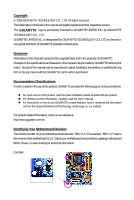
with the product. „ For detailed product information, carefully read the User's Manual. „ For instructions on how to use GIGABYTE's unique features, read or download the information on/from the Support\Motherboard\Technology Guide page on our website. For product-related information, check on our - Gigabyte GA-G31-S3L | Manual - Page 4
Table of Contents Box Contents ...6 OptionalItems...6 GA-G31-S3L Motherboard Layout 7 Block Diagram...8 Chapter 1 Hardware Installation 9 1-1 Memory 17 1-5 Installing an Expansion Card 18 1-6 Back Panel Connectors 19 1-7 Internal Connectors 21 Chapter 2 BIOS Setup 31 2-1 Startup Screen 32 - Gigabyte GA-G31-S3L | Manual - Page 5
Drivers 55 3-2 Software Applications 56 3-3 Driver CD Information 56 3-4 Hardware Information 57 3-5 Contact Us ...57 Chapter 4 Unique Features 59 4-1 Xpress Recovery2 59 4-2 BIOS Update Utilities 64 4-2-1 Updating the BIOS with the Q-Flash Utility 64 4-2-2 Updating the BIOS with the @BIOS - Gigabyte GA-G31-S3L | Manual - Page 6
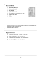
Box Contents GA-G31-S3L motherboard Motherboard driver disk User's Manual Quick Installation Guide One IDE cable and one floppy disk drive cable Two SATA 3Gb/s cables I/O Shield • The box contents above are for reference only and the actual - Gigabyte GA-G31-S3L | Manual - Page 7
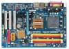
GA-G31-S3L Motherboard Layout KB_MS COAXIAL OPTICAL ATX_12V LGA775 CPU_FAN PWR_FAN VGA LPT GA-G31-S3L USB USB LAN F_AUDIO Intel® G31 AUDIO SYS_FAN1 PCIE_3 ATX DDRII1 CD_IN PCIE_16 DDRII2 DDRII3 DDRII4 RTL8111B PCIE_1 CLR_CMOS SPDIF_O CODEC SPDIF_I PCIE_2 PCI1 PCI2 IT8718 PCI3 - Gigabyte GA-G31-S3L | Manual - Page 8
MHz) PCI Bus LGA775 Processor CPU CLK+/(333/266/200 MHz) Host Interface DDR2 1066/800/667 MHz Intel® G31 Dual Channel Memory GMCH CLK (333/266/200 MHz) Intel® ICH7 CODEC BIOS ATA-100/66/33 IDE Channel 4 SATA 3Gb/s 8 USB Ports IT8718 Floppy LPT Port COM Port PS/2 KB/Mouse - Gigabyte GA-G31-S3L | Manual - Page 9
carefully read the user's manual and follow these procedures: • Prior to installation, do not remove or break motherboard S/N (Serial Number) sticker to damage to system components as well as physical harm to the user. • If you are uncertain about any installation steps or have a problem related to - Gigabyte GA-G31-S3L | Manual - Page 10
supporting up to 4 SATA 3Gb/s devices Š iTE IT8718 chip: - 1 x floppy disk drive connector supporting up to 1 floppy disk drive Š Integrated in the South Bridge Š Up to 8 USB 2.0/1.1 ports (4 on the back panel, 4 via the USB brackets connected to the internal USB headers) GA-G31-S3L Motherboard - Gigabyte GA-G31-S3L | Manual - Page 11
) I/O Controller Š iTE IT8718 chip Hardware Monitor Š System voltage detection Š CPU/System temperature detection Š CPU/System/Power fan speed detection Š CPU overheating warning Š CPU/System/Power fan fail warning Š CPU fan speed control BIOS Š 1 x 8 Mbit flash Š Use of licensed AWARD - Gigabyte GA-G31-S3L | Manual - Page 12
memory is reserved for system usage and therefore the actual memory size is less than the stated amount. For example, 4 GB of memory size will instead be shown as 3.xx GB during system startup. (Note 2) Available functions in Easytune may differ by motherboard model. GA-G31-S3L Motherboard - 12 - - Gigabyte GA-G31-S3L | Manual - Page 13
that the motherboard supports the CPU. (Go to GIGABYTE's website for the latest CPU support list.) . It is not recom- mended that the system bus frequency be set beyond hardware specifications since card, memory, hard drive, etc. 1-3-1 Installing the CPU A. Locate the alignment keys on the motherboard - Gigabyte GA-G31-S3L | Manual - Page 14
B. Follow the steps below to correctly install the CPU into the motherboard CPU socket. Before installing the CPU, make sure to turn off the computer and unplug the properly inserted, replace the load plate and push the CPU socket lever back into its locked position. GA-G31-S3L Motherboard - 14 - - Gigabyte GA-G31-S3L | Manual - Page 15
that the Male and Female push pins are joined closely. (Refer to your CPU cooler installation manual for instructions on installing the cooler.) Step 5: After the installation, check the back of the motherboard. If the push pin is inserted as the picture above, the installation is complete. Step - Gigabyte GA-G31-S3L | Manual - Page 16
motherboard supports the memory. It is recommended that memory of the same capacity, brand, speed, and chips be used. (Go to GIGABYTE's website for the latest memory support memory modules to prevent system's failure to start or incorrect detection of memory modules. GA-G31-S3L Motherboard - 16 - - Gigabyte GA-G31-S3L | Manual - Page 17
power outlet to prevent damage to the memory module. DDR2 DIMMs are not compatible to DDR DIMMs. Be sure to install DDR2 DIMMs on this motherboard. Notch DDR2 DIMM A DDR2 memory module has a notch, so it can only fit in one direction. Follow the steps below to correctly install your memory - Gigabyte GA-G31-S3L | Manual - Page 18
PCI Express x16 slot. Make sure the graphics card is locked by the latch at the end of the PCI Express x16 slot. • Removing the Card: Press the white latch at the end of the PCI Express x16 slot to release the card and then pull the card straight up from the slot. GA-G31-S3L Motherboard - 18 - - Gigabyte GA-G31-S3L | Manual - Page 19
an external audio system that supports digital coaxial audio. Before using this feature, ensure that your audio system provides a coaxial connector, first remove the cable from your device and then remove it from the motherboard. • When removing the cable, pull it straight out from the connector. Do - Gigabyte GA-G31-S3L | Manual - Page 20
to perform different functions via the audio software. Only microphones still MUST be connected to the default Mic in jack ( ). Refer to the instructions on setting up a 2/4/5.1/ 7.1-channel audio configuration in Chapter 5, "Configuring 2/4/5.1/7.1-Channel Audio." GA-G31-S3L Motherboard - 20 - - Gigabyte GA-G31-S3L | Manual - Page 21
devices. • After installing the device and before turning on the computer, make sure the device cable has been securely attached to the connector on the motherboard. - 21 - Hardware Installation - Gigabyte GA-G31-S3L | Manual - Page 22
is used that does not provide the required power, the result can lead to an unstable or unbootable system. • The main power connector is compatible with power supplies with 2x10 power connectors. When using a +5V +5V (Only for 2x12-pinATX) GND (Only for 2x12-pin ATX) GA-G31-S3L Motherboard - 22 - - Gigabyte GA-G31-S3L | Manual - Page 23
12V voltage. The black connector wire is the ground wire. The motherboard supports CPU fan speed control, which requires the use of a CPU the fan headers to prevent your CPU and system from overheating. Overheating may result in damage to the CPU or the system may hang. • These fan headers are not - Gigabyte GA-G31-S3L | Manual - Page 24
master/slave settings for the IDE devices, read the instructions from the device manufacturers.) 2 40 1 39 9) SATAII0 supports a single SATA device. SATAII0 SATAII2 7 17 1 1 71 7 SATAII1 SATAII3 Pin No. 1 2 3 4 5 6 7 Definition GND TXP TXN GND RXN RXP GND GA-G31-S3L Motherboard - Gigabyte GA-G31-S3L | Manual - Page 25
the pin assignments of the motherboard header. Incorrect connection between the module connector and the motherboard header will make the device unable panel audio header supports HD audio by default. If your chassis provides an AC'97 front panel audio module, refer to the instructions on how to - Gigabyte GA-G31-S3L | Manual - Page 26
heard if no problem is detected at system startup. If a problem is detected, the BIOS may issue beeps in different patterns to indicate the problem. Refer to Chapter 5, "Troubleshooting," for information about assignments and the pin assignments are matched correctly. GA-G31-S3L Motherboard - 26 - - Gigabyte GA-G31-S3L | Manual - Page 27
drive to the header. Pin No. Definition 1 1 CD-L 2 GND 3 GND 4 CD-R 14) SPDIF_I (S/PDIF In Header) This header supports digital S/PDIF in and can connect to an audio device that supports digital audio out via an optional S/PDIF in cable. For purchasing the optional S/PDIF in cable, please - Gigabyte GA-G31-S3L | Manual - Page 28
supports digital S/PDIF out and connects a S/PDIF digital audio cable (provided by expansion cards) for digital audio output from your motherboard to certain expansion cards like graphics cards and sound cards. For example, some graphics cards to the USB bracket. GA-G31-S3L Motherboard - 28 - - Gigabyte GA-G31-S3L | Manual - Page 29
the jumper. Failure to do so may cause damage to the motherboard. • After system restart, go to BIOS Setup to load factory defaults (select Load Optimized Defaults) or manually configure the BIOS settings (refer to Chapter 2, "BIOS Setup," for BIOS configurations). - 29 - Hardware Installation - Gigabyte GA-G31-S3L | Manual - Page 30
side (+) and the negative side (-) of the battery (the positive side should face up). • Used batteries must be handled in accordance with local environmental regulations. GA-G31-S3L Motherboard - 30 - - Gigabyte GA-G31-S3L | Manual - Page 31
the GIGABYTE Q-Flash or @BIOS utility. • Q-Flash allows the user to quickly and easily upgrade or back up BIOS without entering the operating system. • @BIOS is a Windows-based utility that searches and downloads the latest version of BIOS from the Internet and updates the BIOS. For instructions on - Gigabyte GA-G31-S3L | Manual - Page 32
, the device boot order will still be based on BIOS Setup settings. You can access Boot Menu again to change the first boot device setting as needed. : Q-Flash Press the key to access the Q-Flash utility directly without having to enter BIOS Setup first. GA-G31-S3L Motherboard - 32 - - Gigabyte GA-G31-S3L | Manual - Page 33
settings for the current submenus Access the Q-Flash utility Display system information Save all the changes and exit the BIOS Setup program Save CMOS to BIOS Load CMOS from BIOS Main Menu Help The onscreen description of a highlighted setup option is displayed - Gigabyte GA-G31-S3L | Manual - Page 34
CMOS and exit BIOS Setup. (Pressing can also carry out this task.) „ Exit Without Saving Abandon all changes and the previous settings remain in effect. Pressing to the confirmation message will exit BIOS Setup. (Pressing can also carry out this task.) GA-G31-S3L Motherboard - 34 - - Gigabyte GA-G31-S3L | Manual - Page 35
[None] [None] [None] [None] [None] Drive A Floppy 3 Mode Support [1.44M, 3.5"] [Disabled] Halt On [All, But Keyboard] Base Memory Extended BIOS automatically detect IDE/SATA devices during the POST. (Default) • None • Manual If no IDE/SATA devices are used, set this item to None so the system - Gigabyte GA-G31-S3L | Manual - Page 36
manually 3 Mode Support Allows you to BIOS POST. Base Memory Also called conventional memory. Typically, 640 KB will be reserved for the MS-DOS operating system. Extended Memory The amount of extended memory. Total Memory The total amount of memory installed on the system. GA-G31-S3L Motherboard - Gigabyte GA-G31-S3L | Manual - Page 37
every time the system boots, or only when you enter BIOS Setup. After system to report read/write errors of the hard drive and to issue warnings when a third party hardware monitor utility is installed. (Default: Disabled) (Note) This item is present only if you install a CPU that supports - Gigabyte GA-G31-S3L | Manual - Page 38
Express card is installed. If you wish to set up a dual view configuration, set this item to Always Enable. (Note) This item is present only if you install a CPU that supports this feature. For more information about Intel CPUs' unique features, please visit Intel's website. GA-G31-S3L Motherboard - Gigabyte GA-G31-S3L | Manual - Page 39
On-Chip Frame Buffer Size Frame buffer size is the total amount of system memory allocated solely for the onboard graphics controller. MS-DOS, for example, will use only this memory for display. Options are: 8MB+1~2MB for GTT (default), 1MB+1~2MB for GTT. - 39 - BIOS Setup - Gigabyte GA-G31-S3L | Manual - Page 40
USB Controller USB 2.0 Controller USB Keyboard Support USB Mouse Support Legacy USB storage detect Azalia Codec Onboard SATA controller. Auto Lets BIOS set SATA devices to automatically configured to Combined mode, you can manually re-configure it to Enhanced mode as GA-G31-S3L Motherboard - 40 - - Gigabyte GA-G31-S3L | Manual - Page 41
Support Allows USB keyboard to be used in MS-DOS. (Default: Disabled) USB Mouse Support 3rd party add-in audio card instead of using the onboard party add-in network card instead of using the Defaults This motherboard incorporates cable cable is attached to the motherboard, the Status fields of - Gigabyte GA-G31-S3L | Manual - Page 42
Mbps in Windows mode or when the LAN Boot ROM is activated. When a Cable Problem Occurs... If a cable problem occurs on a specified pair of wires, the Status field will show Short and thenlength (Enhanced Parallel Port), ECP (Extended Capabilities Port), ECP+EPP. GA-G31-S3L Motherboard - 42 - - Gigabyte GA-G31-S3L | Manual - Page 43
Disabled] Everyday 0 : 0 : 0 [Enabled] [32-bit mode] [Disabled] [Disabled] Enter [Soft-Off] Item system to be awakened from an ACPI sleep state by a wake-up signal from a modem that supports wake-up function. (Default: Enabled) (Note) Supported on Windows® Vista® operating system only. - 43 - BIOS - Gigabyte GA-G31-S3L | Manual - Page 44
off upon the return of the AC power. (Default) Full-On The system is turned on upon the return of the AC power. Memory The system returns to its last known awake state upon the return of the AC power. (Note) Supported on Windows® Vista® operating system only. GA-G31-S3L Motherboard - 44 - - Gigabyte GA-G31-S3L | Manual - Page 45
Assignment Auto 3,4,5,7,9,10,11,12,14,15 PCI2 IRQ Assignment Auto 3,4,5,7,9,10,11,12,14,15 PCI3 IRQ Assignment Auto 3,4,5,7,9,10,11,12,14,15 BIOS auto-assigns IRQ to the first PCI slot. (Default) Assigns IRQ 3,4,5,7,9,10,11,12,14,15 to the first PCI slot - Gigabyte GA-G31-S3L | Manual - Page 46
(default), 60oC/140oF, 70oC/158oF, 80oC/ 176oF, 90oC/194oF. CPU/SYSTEM/POWER FAN Fail Warning Allows the system to emit warning sound if the CPU/system/power fan is not connected or fails. Check the fan condition or fan connection when this occurs. (Default: Disabled) GA-G31-S3L Motherboard - 46 - - Gigabyte GA-G31-S3L | Manual - Page 47
the CPU temperature. You can adjust the fan speed with EasyTune based on system requirements. If disabled, CPU fan runs at full speed. (Default: Enabled be configured if CPU Smart FAN Control is set to Disabled. Auto Lets BIOS autodetect the type of CPU fan installed and sets the optimal CPU fan - Gigabyte GA-G31-S3L | Manual - Page 48
If your system fails to boot after overclocking, please wait for 20 seconds to allow for automated system reboot, or clear the CMOS values to reset the board to default values. (Default: Disabled) (Note) This item appears only if you install a CPU that supports this feature. GA-G31-S3L Motherboard - Gigabyte GA-G31-S3L | Manual - Page 49
frequency be set in accordance with the CPU specifications. PCI Express Frequency (Mhz) Allows you to manually set the PCIe clock frequency. The adjustable range is from 90 MHz to 150 MHz. Auto according to the CPU Host Frequency (Mhz) and System Memory Multiplier settings. - 49 - BIOS Setup - Gigabyte GA-G31-S3L | Manual - Page 50
System Voltage Control Determines whether to manually set the system voltages. Auto lets BIOS automatically set the system voltages as required. Manual allows all voltage control items below to be configurable. (Default: Manual the normal operating voltage of your CPU. GA-G31-S3L Motherboard - 50 - - Gigabyte GA-G31-S3L | Manual - Page 51
this item and then press the key to load the safest BIOS default settings. In case system instability occurs, you may try to load Fail-Safe defaults, which are the safest and most stable BIOS settings for the motherboard. 2-11 Load Optimized Defaults CMOS Setup Utility-Copyright (C) 1984-2007 - Gigabyte GA-G31-S3L | Manual - Page 52
allows you to view the BIOS settings but not to make changes. To clear the password, press on the password item and when requested for the password, press again. The message "PASSWORD DISABLED" will appear, indicating the password has been cancelled. GA-G31-S3L Motherboard - 52 - - Gigabyte GA-G31-S3L | Manual - Page 53
Status Exit Without Saving ` MB Intelligent Tweaker(M.I.T.) ESC: Quit F8: Q-Flash KLJI: Select Item F10: Save & Exit Setup F11: Save CMOS to BIOS F12: Load CMOS from BIOS Save Data to CMOS Press on this item and press the key. This saves the changes to the CMOS and exits the - Gigabyte GA-G31-S3L | Manual - Page 54
GA-G31-S3L Motherboard - 54 - - Gigabyte GA-G31-S3L | Manual - Page 55
other drivers. • After the drivers are installed, follow the onscreen instructions to restart your system. You can install other applications included in the motherboard driver disk. • For USB 2.0 driver support under the Windows XP operating system, please install the Windows XP Service Pack - Gigabyte GA-G31-S3L | Manual - Page 56
all the tools and applications that GIGABYTE develops and some free software. You may press the Install button following an item to install it. 3-3 Driver CD Information This page provides information about the drivers, applications and tools in this driver disk. GA-G31-S3L Motherboard - 56 - - Gigabyte GA-G31-S3L | Manual - Page 57
3-4 Hardware Information This page provides information about the hardware devices on this motherboard. 3-5 Contact Us Check the contacts information of the GIGABYTE headquarter in Taiwan and the overseas branch offices on the last page of this manual. - 57 - Drivers Installation - Gigabyte GA-G31-S3L | Manual - Page 58
GA-G31-S3L Motherboard - 58 - - Gigabyte GA-G31-S3L | Manual - Page 59
system data and perform restoration of it. Supporting NTFS, FAT32, and FAT16 file systems recommended to back up your system soon after the operating system and drivers are installed. • The System Requirements: • Intel® x86 platform • At least 64 MB of system memory • VESA compatible graphics card • - Gigabyte GA-G31-S3L | Manual - Page 60
system.) A. Installing Windows XP and Partitioning the Hard Drive 1. Set CD-ROM drive as the first boot device under "Advanced BIOS Features" in the BIOS Select a file system (for example, NTFS) and begin the installation of the operating system (Figure 3). Figure 3 GA-G31-S3L Motherboard - 60 - - Gigabyte GA-G31-S3L | Manual - Page 61
, you may create new partitions using free space on your hard drive (Figure 6, 7). However, if Disk Management shows the hard drive only contains the System partition without any unallocated space, you will not be able to create new partitions or use Xpress Recovery2. If this occurs, reinstall the - Gigabyte GA-G31-S3L | Manual - Page 62
the Windows operating system. When the Windows operating system is detected, Xpress Recovery2 will begin the backup process (Figure 11). Figure 10 Figure 11 3. When finished, go to Disk Management to check disk allocation. Figure 12 GA-G31-S3L Motherboard Xpress Recovery2 will automatically - Gigabyte GA-G31-S3L | Manual - Page 63
D. Using the Restore Function in Xpress Recovery2 Select RESTORE to restore the backup to your hard drive in case the system breaks down. The RESTORE option will not be present if no backup is created before (Figure 13, 14). Figure 13 Figure 14 E. Removing the Backup 1. - Gigabyte GA-G31-S3L | Manual - Page 64
for G31-S3L F2c . . . . : BIOS Setup/Q-Flash : XpressRecovery2 : Boot Menu : Qflash 11/14/2007-G31-ICH7-6A89OG0HC-00 Because BIOS flashing is potentially risky, please do it with caution. Inadequate BIOS flashing may result in system malfunction. GA-G31-S3L Motherboard - 64 - - Gigabyte GA-G31-S3L | Manual - Page 65
ESC:Reset :Power Off Total size : 0 Free size : 0 3. Select the BIOS update file and press . Make sure the BIOS update file matches your motherboard model. Step 2: The process of the system reading the BIOS file from the floppy disk is displayed on the screen. When the - Gigabyte GA-G31-S3L | Manual - Page 66
Setup F11: Save CMOS to BIOS F12: Load CMOS from BIOS Load Optimized Defaults Press to load BIOS defaults Step 6: Select Save & Exit Setup and then press to save settings to CMOS and exit BIOS Setup. The procedure is complete after the system restarts. GA-G31-S3L Motherboard - 66 - - Gigabyte GA-G31-S3L | Manual - Page 67
and Using @BIOS: Use the motherboard driver disk included with the motherboard to install @BIOS. • Installing the @BIOS utility. • Accessing the @BIOS utility. Select @BIOS and click Install. Click Start>All Programs>GIGABYTE> @BIOS C. Options and Instructions: 1. Save the Current BIOS File In - Gigabyte GA-G31-S3L | Manual - Page 68
motherboard model. Updating the BIOS with an incorrect BIOS file could result in an unbootable system. • If the BIOS update file for your motherboard is not present on the @BIOS server site, please manually download the BIOS update file from GIGABYTE's website and follow the instructions in "Update - Gigabyte GA-G31-S3L | Manual - Page 69
BIOS Setup program. EasyTune 5 Pro provides the following functions (Note 1): overclocking/overvoltage, C.I.A./M.I.B. (Note 2), smart fan control, and hardware monitoring and warning. (For instructions on using EasyTune5 Pro, read or download the information on/from the Support\Motherboard\Utility - Gigabyte GA-G31-S3L | Manual - Page 70
and choose Properties. Step 2: In the ReadyBoost tab, select Use this device. Under Space to reserve for system speed, set the amount of memory space to use for ReadyBoost using the slider or spin box. Click to three times the amount of RAM installed in your computer. GA-G31-S3L Motherboard - 70 - - Gigabyte GA-G31-S3L | Manual - Page 71
the Audio Control Panel. Before installing the audio driver, make sure the "Microsoft UAA Bus driver for High Definition Audio" has been installed from the motherboard driver disk and your operating system has been updated with the latest Service Pack for Windows. (Note) 2/4/5.1/7.1-Channel Audio - Gigabyte GA-G31-S3L | Manual - Page 72
you connect. Then click OK to complete the configuration. B. Configuring Sound Effect: You may configure an audio environment on the Sound Effect tab. C. Activating an AC'97 Front Panel Audio Module: If front headphone plugged in check box. Click OK to complete. GA-G31-S3L Motherboard - 72 - - Gigabyte GA-G31-S3L | Manual - Page 73
for audio processing. A. Installing the S/PDIF In Cable: Step 1: First, attach the connector at the end of the cable to the SPDIF_I header on your motherboard. Step 2: Secure the metal bracket to the chassis back panel with a screw. - 73 - Appendix - Gigabyte GA-G31-S3L | Manual - Page 74
the S/PDIF In/Out Settings dialog box, select an output sampling rate and select (or disable) the output source. Click OK to complete the configuration. GA-G31-S3L Motherboard - 74 - - Gigabyte GA-G31-S3L | Manual - Page 75
5-1-3 Configuring Microphone Recording Step 1: After installing the audio driver, the Audio Manager icon will appear in your system tray. Double-click the icon to access the Audio Control Panel. Step 2: Connect your microphone to the Mic in jack (pink) on the back panel - Gigabyte GA-G31-S3L | Manual - Page 76
list, select Realtek HD Audio Input. Then set the recording sound level properly. Do NOT mute the recording sound, or you will not hear any sound when playing back the recording you just made. Select Realtek HD Audio Input in the Mixer device list GA-G31-S3L Motherboard Recording Control - 76 - - Gigabyte GA-G31-S3L | Manual - Page 77
, click Start, point to All Programs, point to Accessories, point to Entertainment, and then click Sound Recorder to begin the sound recording. 5-1-4 Using the Sound Recorder Recording the Sound: 1. Make sure you have connected the audio input device (e.g. microphone) to the computer. 2. On the - Gigabyte GA-G31-S3L | Manual - Page 78
setting error 1 long, 1 short: Memory or motherboard error 1 long, 2 short: Monitor or graphics card error 1 long, 3 short: Keyboard error 1 long, 9 short: BIOS ROM error Continuous long beeps: Graphics card not inserted properly Continuous short beeps: Power error GA-G31-S3L Motherboard - 78 - - Gigabyte GA-G31-S3L | Manual - Page 79
Procedure If you encounter any troubles during system startup, follow the troubleshooting procedure below to solve the problem. START Turn off the power. Remove all peripherals, connecting cables, and power cord etc. Make sure the motherboard does not short-circuit with the chassis or - Gigabyte GA-G31-S3L | Manual - Page 80
and solved. END If the procedure above is unable to solve your problem, contact the place of purchase or local dealer for help. Or go to the Support\Technical Service Zone page to submit your question. Our customer service staff will reply you as soon as possible. GA-G31-S3L Motherboard - 80 - - Gigabyte GA-G31-S3L | Manual - Page 81
GIGABYTE. Our Commitment to Preserving the Environment In addition to high-efficiency performance, all GIGABYTE motherboards at GIGABYTE are continuing our efforts to develop products that household waste disposal service or where you manual and we will be glad to help you with your effort. - Gigabyte GA-G31-S3L | Manual - Page 82
disposed of properly. China Restriction of Hazardous Substances Table The following table is supplied in compliance with China's Restriction of Hazardous Substances (China RoHS) requirements: GA-G31-S3L Motherboard - 82 - - Gigabyte GA-G31-S3L | Manual - Page 83
- 83 - Appendix - Gigabyte GA-G31-S3L | Manual - Page 84
GA-G31-S3L Motherboard - 84 - - Gigabyte GA-G31-S3L | Manual - Page 85
- 85 - Appendix - Gigabyte GA-G31-S3L | Manual - Page 86
GA-G31-S3L Motherboard - 86 - - Gigabyte GA-G31-S3L | Manual - Page 87
231, Taiwan TEL: +886-2-8912-4888 FAX: +886-2-8912-4003 Tech. and Non-Tech. Support (Sales/Marketing) : http://ggts.gigabyte.com.tw WEB address (English): http://www.gigabyte.com.tw WEB address (Chinese): http://www.gigabyte.tw y G.B.T. INC. - U.S.A. TEL: +1-626-854-9338 FAX: +1-626-854-9339 Tech - Gigabyte GA-G31-S3L | Manual - Page 88
your language in the language list on the top right corner of the website. y GIGABYTE Global Service System To submit a technical or non-technical (Sales/ Marketing) question, please link to : http://ggts.gigabyte.com.tw Then select your language to enter the system. GA-G31-S3L Motherboard - 88 -
-
 1
1 -
 2
2 -
 3
3 -
 4
4 -
 5
5 -
 6
6 -
 7
7 -
8
-
9
-
10
-
11
-
12
-
13
-
14
-
15
-
16
-
17
-
18
-
19
-
20
-
21
-
22
-
23
-
24
-
25
-
26
-
27
-
28
-
29
-
30
-
31
-
32
-
33
-
34
-
35
-
36
-
37
-
38
-
39
-
40
-
41
-
42
-
43
-
44
-
45
-
46
-
47
-
48
-
49
-
50
-
51
-
52
-
53
-
54
-
55
-
56
-
57
-
58
-
59
-
60
-
61
-
62
-
63
-
64
-
65
-
66
-
67
-
68
-
69
-
70
-
71
-
72
-
73
-
74
-
75
-
76
-
77
-
78
-
79
-
80
-
81
-
82
-
83
-
84
-
85
-
86
-
87
-
88
 |
 |

GA-G31-S3L
LGA775 socket motherboard for Intel
®
Core
TM
processor family/
Intel
®
Pentium
®
processor family/Intel
®
Celeron
®
processor family
User's Manual
Rev. 1102
12ME-G31S3L-1102R