Gigabyte GA-G33-DS3R Manual
Gigabyte GA-G33-DS3R Manual
 |
View all Gigabyte GA-G33-DS3R manuals
Add to My Manuals
Save this manual to your list of manuals |
Gigabyte GA-G33-DS3R manual content summary:
- Gigabyte GA-G33-DS3R | Manual - Page 1
GA-G33-DS3R LGA775 socket motherboard for Intel® CoreTM processor family/ Intel® Pentium® processor family/Intel® Celeron® processor family User's Manual Rev. 1004 12ME-G33DS3R-1004R - Gigabyte GA-G33-DS3R | Manual - Page 2
Motherboard GA-G33-DS3R Apr. 13, 2007 Motherboard GA-G33-DS3R Apr. 13, 2007 - Gigabyte GA-G33-DS3R | Manual - Page 3
with the product. „ For detailed product information, carefully read the User's Manual. „ For instructions on how to use GIGABYTE's unique features, read or download the information on/from the Support\Motherboard\Technology Guide page on our website. For product-related information, check on our - Gigabyte GA-G33-DS3R | Manual - Page 4
...6 GA-G33-DS3R Motherboard Layout 7 Block Diagram ...8 Chapter 1 Hardware Installation 9 1-1 Installation Precautions 9 1-2 Product Specifications 10 1-3 22 Chapter 2 BIOS Setup 33 2-1 Startup Screen 34 2-2 The Main Menu 35 2-3 Standard CMOS Features 37 2-4 Advanced BIOS Features 39 2-5 - Gigabyte GA-G33-DS3R | Manual - Page 5
the Q-Flash Utility 66 4-2-2 Updating the BIOS with the @BIOS Utility 69 4-3 EasyTune 5 ...71 4-4 Windows Vista ReadyBoost 72 Chapter 5 Appendix ...73 5-1 Configuring SATA Hard Drive(s 73 5-1-1 Configuring Intel® ICH9R SATA Controllers 73 5-1-2 Configuring GIGABYTE SATA2 SATA Controller 79 - Gigabyte GA-G33-DS3R | Manual - Page 6
Contents GA-G33-DS3R motherboard Motherboard driver disk User's Manual Quick Installation Guide Intel® LGA775 CPU Installation Guide One contents are subject to change without notice. • The motherboard image is for reference only. Optional Items 2-port USB 2.0 bracket (Part No. 12CR1-1UB030-51R) 2- - Gigabyte GA-G33-DS3R | Manual - Page 7
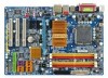
SYS_FAN2 DDRII1 GA-G33-DS3R USB USB LAN F_AUDIO AUDIO SYS_FAN1 Intel® G33 PCIE_3 CD_IN FDD DDRII3 DDRII4 DDRII2 RTL8111B PCIE_16 PCIE_1 CODEC PCIE_2 SPDIF_I PCI1 PCI2 IT8718 PCI3 PWR_FAN CLR_CMOS Intel® ICH9R BATTERY SATAII2 SATAII3 GSATAII0 GIGABYTE SATA2 BIOS GSATAII1 - Gigabyte GA-G33-DS3R | Manual - Page 8
33 IDE Channel GIGABYTE SATA2 LAN RJ45 RTL 8111B PCI Express Bus x 1 x1 3 PCI Express x1 x 1 x 1 x 1 PCIe CLK (100 MHz) PCI Bus Host Interface DDR2 1066/800/667 MHz Intel® G33 Dual Channel Memory GMCH CLK (333/266/200 MHz) Intel® ICH9R BIOS 6 SATA 3Gb/s 12 USB Ports CODEC IT8718 Floppy - Gigabyte GA-G33-DS3R | Manual - Page 9
installation, carefully read the user's manual and follow these procedures: • Prior to installation, do not remove or break motherboard S/N (Serial Number) as well as physical harm to the user. • If you are uncertain about any installation steps or have a problem related to the use of the product, - Gigabyte GA-G33-DS3R | Manual - Page 10
SATA RAID 0, RAID 1, and JBOD Š iTE IT8718 chip: - 1 x floppy disk drive connector supporting up to 1 floppy disk drive Š Integrated in the South Bridge Š Up to 12 USB 2.0/1.1 ports (4 on the back panel, 8 via the USB brackets connected to the internal USB headers) GA-G33-DS3R Motherboard - 10 - - Gigabyte GA-G33-DS3R | Manual - Page 11
English Internal Connectors Š 1 x 24-pin ATX main power connector Š 1 x 4-pin ATX 12V power connector Š optical S/PDIF Out connector Š 1 x D-Sub port Š 4 x USB 2.0/1.1 ports Š 1 x RJ-45 port Š 6 x audio jacks BIOS Š 1 x 8 Mbit flash Š Use of licensed AWARD BIOS Š PnP 1.0a, DMI 2.0, SM BIOS - Gigabyte GA-G33-DS3R | Manual - Page 12
fan speed control function is supported will depend on the CPU cooler you install. (Note 3) Available functions in Easytune may differ by motherboard model. (Note 4) Due to chipset limitation, Intel ICH9R RAID driver does not support Windows 2000 operating system. GA-G33-DS3R Motherboard - 12 - - Gigabyte GA-G33-DS3R | Manual - Page 13
enabled (Refer to Chapter 2, "BIOS Setup," "Advanced BIOS Features," for instructions on enabling the HT Technology.) 1-3-1 Installing the CPU A. Locate the alignment keys on the motherboard CPU socket and the notches on the CPU. LGA775 CPU Socket Alignment Key LGA 775 CPU Alignment Key Pin One - Gigabyte GA-G33-DS3R | Manual - Page 14
pin one corner of the CPU socket (or you may align the CPU notches with the socket alignment keys) and gently insert the CPU into position. Step 5: Once the CPU is properly inserted, replace the load plate and push the CPU socket lever back into its locked position. GA-G33-DS3R Motherboard - 14 - - Gigabyte GA-G33-DS3R | Manual - Page 15
below to correctly install the CPU cooler on the motherboard. (The following procedure uses Intel® boxed cooler as the example cooler.) Step 1: CPU cooler installation manual for instructions on installing the cooler.) Step 5: After the installation, check the back of the motherboard. If the push - Gigabyte GA-G33-DS3R | Manual - Page 16
installed, a message which says memory is operating in Flex Memory Mode will appear during the POST. Intel® Flex Memory Technology offers greater flexibility to upgrade by allowing different memory sizes to be populated and remain in Dual Channel mode/performance. GA-G33-DS3R Motherboard - 16 - - Gigabyte GA-G33-DS3R | Manual - Page 17
are not compatible to DDR DIMMs. Be sure to install DDR2 DIMMs on this motherboard. Notch DDR2 DIMM A DDR2 memory module has a notch, so it can only Spread the retaining clips at both ends of the memory socket. Place the memory module on the socket. As indicated in the picture on the left, place - Gigabyte GA-G33-DS3R | Manual - Page 18
expansion card: • Make sure the motherboard supports the expansion card. Carefully read the manual that came with your expansion card. necessary, go to BIOS Setup to make any required BIOS changes for your expansion card(s). 7. Install the driver provided with the GA-G33-DS3R Motherboard - 18 - - Gigabyte GA-G33-DS3R | Manual - Page 19
secure the SATA bracket to the chassis back panel with a screw. Step 2: Connect the SATA cable from the bracket to the SATA port on your motherboard. Step 3: Step 4: Connect the power Plug one end of the cable from the SATA signal cable into bracket to the power the external SATA supply - Gigabyte GA-G33-DS3R | Manual - Page 20
to a back panel connector, first remove the cable from your device and then remove it from the motherboard. • When removing the cable, pull it straight out from the connector. Do not rock it side to side to prevent an electrical short inside the cable connector. GA-G33-DS3R Motherboard - 20 - - Gigabyte GA-G33-DS3R | Manual - Page 21
to perform different functions via the audio software. Only microphones still MUST be connected to the default Mic in jack ( ). Refer to the instructions on setting up a 2/4/5.1/ 7.1-channel audio configuration in Chapter 5, "Configuring 2/4/5.1/7.1-Channel Audio." - 21 - Hardware Installation - Gigabyte GA-G33-DS3R | Manual - Page 22
12 1) ATX_12V 2) ATX 3) CPU_FAN 4) SYS_FAN1 5) SYS_FAN2 6) PWR_FAN 7) FDD 8) IDE1 9) SATAII0/1/2/3/4/5 10) GSATAII0/1 11) PWR_LED 12) F_PANEL 13) F_AUDIO 14) CD_IN 15) SPDIF_I 16) F_USB1/F_USB2/F_USB3 has been securely attached to the connector on the motherboard. GA-G33-DS3R Motherboard - 22 - - Gigabyte GA-G33-DS3R | Manual - Page 23
the main power connector on the motherboard. Do not insert the power supply cable into pins under the protective cover when using a 2x10 power supply. 3 4 1 2 ATX_12V ATX_12V : Pin No. 1 2 3 4 Definition GND GND +12V +12V 12 24 1 13 ATX ATX : Pin No. 1 2 3 4 5 6 7 8 9 10 - Gigabyte GA-G33-DS3R | Manual - Page 24
disk drives supported are: 360 KB, 720 KB, 1.2 MB, 1.44 MB, and 2.88 MB. Before connecting a floppy disk drive, be sure to locate pin 1 of the connector and the floppy disk drive cable. The pin 1 of the cable is typically designated by a stripe of different color. 34 33 GA-G33-DS3R Motherboard - Gigabyte GA-G33-DS3R | Manual - Page 25
with SATA 1.5Gb/s standard. Each SATA connector supports a single SATA device. The ICH9R controller supports RAID 0, RAID 1, RAID 5 and RAID 10. Refer to Chapter 5, "Configuring SATA Hard Drive(s)," for instructions on configuring a RAID array. Pin No. Definition 7 SATAII2 17 1 SATAII0 - Gigabyte GA-G33-DS3R | Manual - Page 26
connector supports a single SATA device. The GIGABYTE SATA2 controller supports RAID 0 and RAID 1. Refer to Chapter 5, "Configuring SATA Hard Drive(s)," for instructions on configuring a RAID array. 1 3 MPD- System Status LED S0 On S1 Blinking S3/S4/S5 Off GA-G33-DS3R Motherboard - 26 - - Gigabyte GA-G33-DS3R | Manual - Page 27
problem is detected at system startup. If a problem is detected, the BIOS may issue beeps in different patterns to indicate the problem. Refer to Chapter 5, "Troubleshooting may differ by chassis. A front panel module mainly consists of power switch, reset switch, power LED, hard drive activity LED, - Gigabyte GA-G33-DS3R | Manual - Page 28
LINE2_L 9 Line Out (L) 10 GND 10 NC • The front panel audio header supports HD audio by default. If your chassis provides an AC'97 front panel audio module, refer to the instructions on how to activate . 1 Pin No. Definition 1 CD-L 2 GND 3 GND 4 CD-R GA-G33-DS3R Motherboard - 28 - - Gigabyte GA-G33-DS3R | Manual - Page 29
header supports digital S/PDIF in and can connect to an audio device that supports digital 10 2 2 Power (5V) 3 USB DX- 4 USB DY- 5 USB DX+ 6 USB DY+ 7 GND 8 GND 9 No Pin 10 NC • Do not plug the IEEE 1394 bracket (2x5-pin) cable into the USB header. • Prior to installing the USB - Gigabyte GA-G33-DS3R | Manual - Page 30
ANo Pin 18) CI (Chassis Intrusion Header) This motherboard provides a chassis detection feature that detects if the chassis cover has been removed. This function requires a chassis with chassis intrusion detection design. Pin No. Definition 1 1 Signal 2 GND GA-G33-DS3R Motherboard - 30 - - Gigabyte GA-G33-DS3R | Manual - Page 31
(e.g. date information and BIOS configurations) and reset the CMOS values to factory driver for High Definition Audio" has been installed from the motherboard driver disk and your operating system has been updated with the latest Service Pack for Windows before installing the graphics card driver - Gigabyte GA-G33-DS3R | Manual - Page 32
English 21) BATTERY The battery provides power to keep the values (such as BIOS configurations, date, and time information) in the CMOS when the computer is turned should face up). • Used batteries must be handled in accordance with local environmental regulations. GA-G33-DS3R Motherboard - 32 - - Gigabyte GA-G33-DS3R | Manual - Page 33
the GIGABYTE Q-Flash or @BIOS utility. Q-Flash allows the user to quickly and easily upgrade or back up BIOS without entering the operating system. @BIOS is a Windows-based utility that searches and downloads the latest version of BIOS from the Internet and updates the BIOS. For instructions on - Gigabyte GA-G33-DS3R | Manual - Page 34
, the device boot order will still be based on BIOS Setup settings. You can access Boot Menu again to change the first boot device setting as needed. : Q-Flash Press the key to access the Q-Flash utility directly without having to enter BIOS Setup first. GA-G33-DS3R Motherboard - 34 - - Gigabyte GA-G33-DS3R | Manual - Page 35
User Password Save & Exit Setup Exit Without Saving ESC: Quit F8: Q-Flash KLJI: Select Item F10: Save & Exit Setup F11: Save CMOS to BIOS F12: Load CMOS from BIOS Time, Date, Hard Disk Type... BIOS exit the BIOS Setup program Save CMOS to BIOS Load CMOS from BIOS Main Menu Help - Gigabyte GA-G33-DS3R | Manual - Page 36
CMOS and exit BIOS Setup. (Pressing can also carry out this task.) „ Exit Without Saving Abandon all changes and the previous settings remain in effect. Pressing to the confirmation message will exit BIOS Setup. (Pressing can also carry out this task.) GA-G33-DS3R Motherboard - 36 - Gigabyte GA-G33-DS3R | Manual - Page 37
] [None] [None] [None] Drive A Floppy 3 Mode Support [1.44M, 3.5"] [Disabled] Halt On [All, But Keyboard] three methods below: • Auto • None Lets BIOS automatically detect IDE/SATA devices during the POST. faster system startup. • Manual Allows you to manually enter the specifications of the - Gigabyte GA-G33-DS3R | Manual - Page 38
manually 3 Mode Support Allows you BIOS POST. Base Memory Also called conventional memory. Typically, 640 KB will be reserved for the MS-DOS operating system. Extended Memory The amount of extended memory. Total Memory The total amount of memory installed on the system. GA-G33-DS3R Motherboard - Gigabyte GA-G33-DS3R | Manual - Page 39
, USB-FDD, USB-ZIP, USB-CDROM, USB-HDD, Legacy LAN, Disabled. Password Check Specifies whether a password is required every time the system boots, or only when you enter BIOS Setup. After configuring this item, set the password(s) under the Set Supervisor/User Password item in the BIOS Main Menu - Gigabyte GA-G33-DS3R | Manual - Page 40
Windows NT4.0. (Default: Disabled) No-Execute Memory Protect (Note) Enables or disables Intel whether to display the GIGABYTE Logo at system startup. supports this feature. For more information about Intel CPUs' unique features, please visit Intel's website. GA-G33-DS3R Motherboard - 40 - - Gigabyte GA-G33-DS3R | Manual - Page 41
graphics controller. MS-DOS, for example, will use only this memory for display. Options are: 8MB+1~2MB for GTT (default), 1MB+1~2MB for GTT. - 41 - BIOS Setup - Gigabyte GA-G33-DS3R | Manual - Page 42
. (Default: Enabled) Disabled will turn off all of the USB functionalities below. USB 2.0 Controller Enables or disables the integrated USB 2.0 controller. (Default: Enabled) USB Keyboard Support Allows USB keyboard to be used in MS-DOS. (Default: Disabled) GA-G33-DS3R Motherboard - 42 - - Gigabyte GA-G33-DS3R | Manual - Page 43
transmission speed Cable Length Displays the approximate length of the attached LAN cable. Note: The Gigabit hub will only operate at a speed of 10/100Mbps in MS-DOS mode; it will operate at a normal speed of 10/100/1000Mbps in Windows mode or when the LAN Boot ROM is activated. - 43 - BIOS Setup - Gigabyte GA-G33-DS3R | Manual - Page 44
LAN cable. Onboard LAN Boot ROM Allows you to decide whether to activate the boot ROM integrated with the onboard LAN chip. (Default: Disabled) Onboard SATA/IDE Device (GIGABYTE SATA2 EPP (Enhanced Parallel Port), ECP (Extended Capabilities Port), ECP+EPP. GA-G33-DS3R Motherboard - 44 - - Gigabyte GA-G33-DS3R | Manual - Page 45
at least 1A on the 5VSB lead. (Default: Enabled) Power On by Ring Allows the system to be awakened from an ACPI sleep state by a wake-up signal from a modem that supports wake-up function. (Default: Enabled) (Note) Supported on Windows® Vista® operating system only. - 45 - BIOS Setup - Gigabyte GA-G33-DS3R | Manual - Page 46
on the system. Power On By Keyboard Allows the system to be turned on by a PS/2 keyboard wake-up event. Note: you need an ATX power supply providing at least 1A on the 5VSB lead. return of the AC power. (Note) Supported on Windows® Vista® operating system only. GA-G33-DS3R Motherboard - 46 - - Gigabyte GA-G33-DS3R | Manual - Page 47
-assigns IRQ to the first PCI slot. (Default) Assigns IRQ 3,4,5,7,9,10,11,12,14,15 to the first PCI slot. BIOS auto-assigns IRQ to the second PCI slot. (Default) Assigns IRQ 3,4,5,7,9,10,11,12,14,15 to the second PCI slot. BIOS auto-assigns IRQ to the third PCI slot. (Default) Assigns IRQ - Gigabyte GA-G33-DS3R | Manual - Page 48
Help F7: Optimized Defaults Reset Case Open Status Keeps or boot. (Default: Disabled) Case Opened Displays the detection status of the chassis intrusion detection device attached to the motherboard temperature exceeds the threshold, BIOS will emit warning sound. GA-G33-DS3R Motherboard - 48 - - Gigabyte GA-G33-DS3R | Manual - Page 49
speed. Auto Lets BIOS control CPU fan speed. (Default) Intel(R) QST Allows CPU fan speed to be controlled by the Intel Quiet System Technology (QST). This feature requires the installation of Intel Host Embedded Control Interface (HECI) driver from the motherboard driver disk. Legacy Allows - Gigabyte GA-G33-DS3R | Manual - Page 50
1] [Manual] [ users BIOS boot after overclocking, please wait for 20 seconds to allow for automated system reboot, or clear the CMOS values to reset the board to default values. (Default: Disabled) (Note) This item appears only if you install a CPU that supports this feature. GA-G33-DS3R Motherboard - Gigabyte GA-G33-DS3R | Manual - Page 51
two different memory timing configurations. If your system becomes unstable after you overclock the DDR2 memory, select Option 1 or Option 2 to help Determines whether to manually set the system voltages. Auto lets BIOS automatically set the system voltages as required. Manual allows all voltage - Gigabyte GA-G33-DS3R | Manual - Page 52
result in damage to your CPU or reduce the useful life of the CPU. Normal CPU Vcore Displays the normal operating voltage of your CPU. GA-G33-DS3R Motherboard - 52 - - Gigabyte GA-G33-DS3R | Manual - Page 53
motherboard. 2-11 Load Optimized Defaults CMOS Setup Utility-Copyright (C) 1984-2007 Award Software ` Standard CMOS Features Load Fail-Safe Defaults ` Advanced BIOS Features Load Optimized Defaults ` Integrated Peripherals Set Supervisor Password ` Power Management Setup Set User Password - Gigabyte GA-G33-DS3R | Manual - Page 54
allows you to view the BIOS settings but not to make changes. To clear the password, press on the password item and when requested for the password, press again. The message "PASSWORD DISABLED" will appear, indicating the password has been cancelled. GA-G33-DS3R Motherboard - 54 - - Gigabyte GA-G33-DS3R | Manual - Page 55
Press on this item and press the key. This saves the changes to the CMOS and exits the BIOS Setup program. Press or to return to the BIOS Setup Main Menu. 2-14 Exit Without Saving CMOS Setup Utility-Copyright (C) 1984-2007 Award Software ` Standard CMOS Features Load Fail - Gigabyte GA-G33-DS3R | Manual - Page 56
English GA-G33-DS3R Motherboard - 56 - - Gigabyte GA-G33-DS3R | Manual - Page 57
other drivers. • After the drivers are installed, follow the onscreen instructions to restart your system. You can install other applications included in the motherboard driver disk. • For USB 2.0 driver support under the Windows XP operating system, please install the Windows XP Service Pack - Gigabyte GA-G33-DS3R | Manual - Page 58
all the tools and applications that GIGABYTE develops and some free software. You may press the Install button following an item to install it. 3-3 Driver CD Information This page provides information about the drivers, applications and tools in this driver disk. GA-G33-DS3R Motherboard - 58 - - Gigabyte GA-G33-DS3R | Manual - Page 59
English 3-4 Hardware Information This page provides information about the hardware devices on this motherboard. 3-5 Contact Us Check the contacts information of the GIGABYTE headquarter in Taiwan and the overseas branch offices on the last page of this manual. - 59 - Drivers Installation - Gigabyte GA-G33-DS3R | Manual - Page 60
English GA-G33-DS3R Motherboard - 60 - - Gigabyte GA-G33-DS3R | Manual - Page 61
in advanced (10 GB or and drivers are installed. Windows® XP with SP1 or later • Xpress Recovery and Xpress Recovery2 are different utilities. For example, a backup file created with Xpress Recovery cannot be restored using Xpress Recovery2. • USB hard drives are not supported. • Hard drives in RAID - Gigabyte GA-G33-DS3R | Manual - Page 62
for Xpress Recovery2 (10 GB or more is recommended; actual size requirements vary, depending on the amount of data) (Figure 2). Figure 1 Figure 2 3. Select a file system (for example, NTFS) and begin the installation of the operating system (Figure 3). Figure 3 GA-G33-DS3R Motherboard - 62 - - Gigabyte GA-G33-DS3R | Manual - Page 63
English 4. After the operating system is installed, right-click the My Computer icon on your desktop and select Manage (Figure 4). Go to Computer Management to check disk allocation. Xpress Recovery2 will save the backup file to the unallocated space (black stripe along the top)(Figure 5). Please - Gigabyte GA-G33-DS3R | Manual - Page 64
drive contains the Windows operating system. When the Windows operating system is detected, Xpress Recovery2 will begin the backup process (Figure 11). Figure 10 Figure 11 3. When finished, go to Disk Management to check disk allocation. Figure 12 GA-G33-DS3R Motherboard Xpress Recovery2 will - Gigabyte GA-G33-DS3R | Manual - Page 65
English D. Using the Restore Function in Xpress Recovery2 Select RESTORE to restore the backup to your hard drive in case the system breaks down. The RESTORE option will not be present if no backup is created before (Figure 13, 14). Figure 13 Figure 14 E. Removing the Backup 1. If you wish to - Gigabyte GA-G33-DS3R | Manual - Page 66
BIOS for G33-DS3R F1b . . . . : BIOS Setup/Q-Flash : XpressRecovery2 : Boot Menu : Qflash 04/03/2007-G33-ICH9-6A79OG01C-00 Because BIOS flashing is potentially risky, please do it with caution. Inadequate BIOS flashing may result in system malfunction. GA-G33-DS3R Motherboard - Gigabyte GA-G33-DS3R | Manual - Page 67
arrow key to select Update BIOS from Drive and press . • The Save Main BIOS to Drive option allows you to save the current BIOS file. • Q-Flash only supports USB flash drive or hard drives using FAT32/16/12 file system. • If the BIOS update file is saved to a hard drive in RAID/AHCI mode or - Gigabyte GA-G33-DS3R | Manual - Page 68
Setup F11: Save CMOS to BIOS F12: Load CMOS from BIOS Load Optimized Defaults Press to load BIOS defaults Step 6: Select Save & Exit Setup and then press to save settings to CMOS and exit BIOS Setup. The procedure is complete after the system restarts. GA-G33-DS3R Motherboard - 68 - - Gigabyte GA-G33-DS3R | Manual - Page 69
the motherboard driver disk included with the motherboard to install @BIOS. • Installing the @BIOS utility. • Accessing the @BIOS utility. Click Start>All Programs>GIGABYTE> @BIOS>@BIOS Select @BIOS and click Install. C. Options and Instructions: 1. Save the Current BIOS File In the main dialog - Gigabyte GA-G33-DS3R | Manual - Page 70
BIOS file matches your motherboard model. Updating the BIOS with an incorrect BIOS file could result in an unbootable system. Step 4: As the system boots, press to enter the BIOS Setup program. Select Load Optimized Defaults and press to load BIOS defaults. GA-G33-DS3R Motherboard - Gigabyte GA-G33-DS3R | Manual - Page 71
the BIOS Setup program. EasyTune 5 provides the following functions (Note 1): overclocking/overvoltage, C.I.A./ M.I.B. (Note 2), smart fan control, and hardware monitoring and warning. (For instructions on using EasyTune5, read or download the information on/from the Support\Motherboard\Utility - Gigabyte GA-G33-DS3R | Manual - Page 72
the slider or spin box. Click Apply and then OK to turn on ReadyBoost. • The USB flash drive must have at least 256 MB of space. • The recommended amount of memory to use for ReadyBoost acceleration is one to three times the amount of RAM installed in your computer. GA-G33-DS3R Motherboard - 72 - - Gigabyte GA-G33-DS3R | Manual - Page 73
model and capacity). If you do not want to create RAID, you may prepare only one hard drive. • An empty formatted floppy disk. • Windows Vista/XP/2000 (Note 3) setup disk. • Motherboard driver disk. 5-1-1 Configuring Intel® ICH9R SATA Controllers A. Installing SATA hard drive(s) in your computer - Gigabyte GA-G33-DS3R | Manual - Page 74
Defaults Step 2: Save changes and exit BIOS Setup. The BIOS Setup menus described in this section may differ from the exact settings for your motherboard. The actual BIOS Setup menu options you will see shall depend on the motherboard you have and the BIOS version. GA-G33-DS3R Motherboard - 74 - - Gigabyte GA-G33-DS3R | Manual - Page 75
C. Configuring a RAID array in RAID BIOS Enter the RAID BIOS setup utility to configure a RAID array. Skip this step and proceed to the installation of Windows operating system for a non-RAID configuration. Step 1: After the POST memory test begins and before the operating system boot begins, look - Gigabyte GA-G33-DS3R | Manual - Page 76
: RAID Level : Disks : Strip Size : Capacity : Volume0 RAID0(Stripe) Select Disks 128KB 223.6 GB Create Volume [ HELP ] The following are typical values: RAID0 - 128KB RAID10 - 64KB RAID5 - 64KB [K L ]-Change [TAB]-Next [ESC]-Previous Menu Figure 5 [ENTER]-Select GA-G33-DS3R Motherboard - Gigabyte GA-G33-DS3R | Manual - Page 77
option ROM v7.5.0.1014 ICH9R wRAID5 Copyright(C) 2003-07 Intel Corporation. All Rights Reversed. [ MAIN MENU ] 1. Create RAID Volume 2. Delete RAID Volume 3. Reset Disks to Non-RAID 4. Exit RAID Volumes : ID Name 0 Volume0 Physical Disks : Port Drive Model 0 ST3120026AS 1 ST3120026AS - Gigabyte GA-G33-DS3R | Manual - Page 78
] ALL DATA IN THE[VHOELLUPM] E WILL BE LOST! Are you sure you want to delete "Volume0"? (Y/N) : Deleting a volume will reset the disks to non-RAID. WARNING: ALL DISK DATA WILL BE DELETED. [K L ]-Select [ESC]-Previous Menu Figure 8 [DEL]-Delete Volume GA-G33-DS3R Motherboard - 78 - - Gigabyte GA-G33-DS3R | Manual - Page 79
(C) 1984-2007 Award Software Integrated Peripherals SATA RAID/AHCI Mode SATA Port0~3 Native Mode USB Controller USB 2.0 Controller USB Keyboard Support USB Mouse Support Legacy USB storage detect Azalia Codec Onboard H/W LAN ` SMART LAN Onboard LAN Boot ROM Onboard SATA/IDE Device Onboard SATA/IDE - Gigabyte GA-G33-DS3R | Manual - Page 80
RAID [ RAID Disk Drive List ] [IJTAB]-Switch Window [KL]-Select ITEM [ENTER]-Action Figure 3 [ESC]-Exit Note: In the main screen, you can select a hard drive in the Hard Disk Drive List block and press to see detailed information about the selected hard drive. GA-G33-DS3R Motherboard - Gigabyte GA-G33-DS3R | Manual - Page 81
HDD1: ST3120026AS Available 120 GB 120 GB Type/Status Non-RAID Non-RAID Confirm Creation [ RAID Disk Drive List ] [ Help ] Enter RAID Name Enter a string between 1 to 16 characters in length for the created RAID drive to be identified by system BIOS or OS. [IJ]-Move Cursor [DEL,BS]-Delete - Gigabyte GA-G33-DS3R | Manual - Page 82
Non-RAID Non-RAID Confirm Creation [ RAID Disk Drive List ] Create RAID [onHethlpe ]select HDD(Y/N)?Y CONFIRM RAID CREATION ALL DATA ON THE SELECTED HARD DISK WILL BE LOST WHEN EXIT WITH SAVING [KL]-Switch Unit [DEL,BS]-Delete Number Figure 7 [ENTER]-Next [ESC]-Abort GA-G33-DS3R Motherboard - Gigabyte GA-G33-DS3R | Manual - Page 83
RAID Inside [ RAID Disk Drive List ] Model Name RDD0: GRAID RAID Level 0-Stripe Capacity Status 240 GB Normal Members(HDDx) 01 [IJTAB]-Switch Window [KL]-Select ITEM [ENTER]-Action Figure 8 [ESC]-Exit To check more detailed information about the array, use the key while in the Main - Gigabyte GA-G33-DS3R | Manual - Page 84
Inside RAID Inside [ RAID Disk Drive List ] Model Name ` RDD0: GRAID ALL DATA ON THE RAID WILL LOST!! ARE YOU SURE TO DELETE (Y/N)? N RAID Level Capacity Status 0-Stripe 240 GB Normal Members(HDDx) 01 [KL]-Select RAID [SPACE]-Mark Delete [DEL]-Confirm Figure 11 GA-G33-DS3R Motherboard - Gigabyte GA-G33-DS3R | Manual - Page 85
be recognized during the Windows setup process. First of all, copy the driver for the SATA controller from the motherboard driver disk to a floppy disk. See the instructions below about how to copy the driver in MS-DOS mode(Note). Prepare a startup disk that has CD-ROM support and a blank formatted - Gigabyte GA-G33-DS3R | Manual - Page 86
manufacturer, press S. * If you do not have any device support disks from a mass storage device manufacturer, or do not want to specify additional mass storage devices for use with Windows, press ENTER. S=Specify Additional Device ENTER=Continue F3=Exit Figure 2 GA-G33-DS3R Motherboard - 86 - - Gigabyte GA-G33-DS3R | Manual - Page 87
correct SATA RAID/AHCI driver again from the motherboard driver disk. When the screen as shown below appears, press to continue the driver installation from the floppy disk. The driver installation will be finished in about one minute. Windows Setup Setup will load support for the following - Gigabyte GA-G33-DS3R | Manual - Page 88
manufacturer, press S. * If you do not have any device support disks from a mass storage device manufacturer, or do not want to specify additional mass storage devices for use with Windows, press ENTER. S=Specify Additional Device ENTER=Continue F3=Exit Figure 6 GA-G33-DS3R Motherboard - 88 - - Gigabyte GA-G33-DS3R | Manual - Page 89
Step 4: After the SATA RAID/AHCI driver installation is completed, you can proceed with the Windows XP installation. WindowsXP Professional Setup Welcome to Setup. This port of the Setup program prepares Microsoft(R) Windows (R) XP to run on your computer. To set up Windows XP now, press ENTER - Gigabyte GA-G33-DS3R | Manual - Page 90
Line in jack and manually configure the jack for microphone functionality. • If your front panel audio supports Intel HD Audio standard, you the motherboard driver disk and your operating system has been updated with the latest Service Pack for Windows. speaker out. GA-G33-DS3R Motherboard - 90 - - Gigabyte GA-G33-DS3R | Manual - Page 91
English Step 2: Click the Audio I/O tab. In the speaker list on the left, select 2CH Speaker, 4CH Speaker, 6CH Speaker, or 8CH Speaker according to the type of speaker configuration you wish to set up. Step 3: Everytime you connect an audio device to an audio jack, the Connected device box appears. - Gigabyte GA-G33-DS3R | Manual - Page 92
for audio processing. A. Installing the S/PDIF In Cable: Step 1: First, attach the connector at the end of the cable to the SPDIF_IN header on your motherboard. Step 2: Secure the metal bracket to the chassis back panel with a screw. GA-G33-DS3R Motherboard - 92 - - Gigabyte GA-G33-DS3R | Manual - Page 93
English S/PDIF Out: The S/PDIF out jacks can transmit audio signals to an external decoder for decoding to get the best audio quality. B. Conneting a S/PDIF out Cable Connect a S/PDIF coaxial cable or a S/PDIF optical cable (either one) to an external decoder for transmitting the S/PDIF digital - Gigabyte GA-G33-DS3R | Manual - Page 94
English 5-2-3 Configuring Microphone Recording Step 1: After installing the audio driver, the Audio Manager icon will appear in your system tray. Double-click the icon to access Locate the Volume icon in your system tray and click it to open the volume control panel GA-G33-DS3R Motherboard - 94 - - Gigabyte GA-G33-DS3R | Manual - Page 95
English Step 4: To hear the sound being recorded during the record- ing process when using the microphone function on or the front panel, do not select the Mute check box under Front Pink In or Front Green In in Master Volume. It is recommended that you set the volume at a middle level. To - Gigabyte GA-G33-DS3R | Manual - Page 96
the Stop button . 5. You may use the Fast Forward button to move to the beginning of a file or the Fast Backward button to the end. GA-G33-DS3R Motherboard - 96 - - Gigabyte GA-G33-DS3R | Manual - Page 97
English 5-3 Troubleshooting 5-3-1 Frequently Asked Questions To read more FAQs for your motherboard, please go to the Support\Motherboard\FAQ page on GIGABYTE's website. Q: In the BIOS Setup program, why are some BIOS options missing? A: Some advanced options are hidden in the BIOS Setup program. - Gigabyte GA-G33-DS3R | Manual - Page 98
insert the memory into the memory socket. The problem is verified and solved. Press to enter BIOS Setup. Select "Load Fail-Safe Defaults" (or "Load Optimized Defaults"). Select "Save & Exit Setup" to save changes and exit BIOS Setup. A (Continued...) GA-G33-DS3R Motherboard - 98 - - Gigabyte GA-G33-DS3R | Manual - Page 99
is verified and solved. END If the procedure above is unable to solve your problem, contact the place of purchase or local dealer for help. Or go to the Support\Technical Service Zone page to submit your question. Our customer service staff will reply you as soon as possible. - 99 - Appendix - Gigabyte GA-G33-DS3R | Manual - Page 100
product. Restriction of Hazardous Substances (RoHS) Directive Statement GIGABYTE products have not intended to add and safe from office, your household waste disposal service or where you purchased the user's manual and we will be glad to help you with your effort. GA-G33-DS3R Motherboard - 100 - - Gigabyte GA-G33-DS3R | Manual - Page 101
English Finally, we suggest that you practice other environmentally friendly actions by understanding and using the energy-saving features of this product (where applicable), recycling the inner and outer packaging (including shipping containers) this product was delivered in, and by disposing of - Gigabyte GA-G33-DS3R | Manual - Page 102
English GA-G33-DS3R Motherboard - 102 - - Gigabyte GA-G33-DS3R | Manual - Page 103
) FAX: +1-626-854-9339 Correo: [email protected] Tech. Support: http://rma.gigabyte-usa.com Web address: http://www.gigabyte.com.mx Singapore GIGA-BYTE SINGAPORE PTE. LTD. WEB address : http://www.gigabyte.sg Thailand WEB address : http://th.giga-byte.com Vietnam WEB address : http://www - Gigabyte GA-G33-DS3R | Manual - Page 104
your language in the language list on the top right corner of the website. GIGABYTE Global Service System To submit a technical or non-technical (Sales/ Marketing) question, please link to : http://ggts.gigabyte.com.tw Then select your language to enter the system. GA-G33-DS3R Motherboard - 104 -
-
 1
1 -
 2
2 -
 3
3 -
 4
4 -
 5
5 -
 6
6 -
 7
7 -
8
-
9
-
10
-
11
-
12
-
13
-
14
-
15
-
16
-
17
-
18
-
19
-
20
-
21
-
22
-
23
-
24
-
25
-
26
-
27
-
28
-
29
-
30
-
31
-
32
-
33
-
34
-
35
-
36
-
37
-
38
-
39
-
40
-
41
-
42
-
43
-
44
-
45
-
46
-
47
-
48
-
49
-
50
-
51
-
52
-
53
-
54
-
55
-
56
-
57
-
58
-
59
-
60
-
61
-
62
-
63
-
64
-
65
-
66
-
67
-
68
-
69
-
70
-
71
-
72
-
73
-
74
-
75
-
76
-
77
-
78
-
79
-
80
-
81
-
82
-
83
-
84
-
85
-
86
-
87
-
88
-
89
-
90
-
91
-
92
-
93
-
94
-
95
-
96
-
97
-
98
-
99
-
100
-
101
-
102
-
103
-
104
 |
 |

GA-G33-DS3R
LGA775 socket motherboard for Intel
®
Core
TM
processor family/
Intel
®
Pentium
®
processor family/Intel
®
Celeron
®
processor family
User's Manual
Rev. 1004
12ME-G33DS3R-1004R