Gigabyte GA-H55-UD3H Manual
Gigabyte GA-H55-UD3H Manual
 |
View all Gigabyte GA-H55-UD3H manuals
Add to My Manuals
Save this manual to your list of manuals |
Gigabyte GA-H55-UD3H manual content summary:
- Gigabyte GA-H55-UD3H | Manual - Page 1
GA-H55-UD3H LGA1156 socket motherboard for Intel® Core™ i7 processor family/ Intel® Core™ i5 processor family/ Intel® Core™ i3 processor family User's Manual Rev. 1001 12ME-H55UD3H-1001R - Gigabyte GA-H55-UD3H | Manual - Page 2
Motherboard GA-H55-UD3H Dec. 11, 2009 Motherboard GA-H55-UD3H Dec. 11, 2009 - Gigabyte GA-H55-UD3H | Manual - Page 3
the product. For detailed product information, carefully read the User's Manual. For instructions on how to use GIGABYTE's unique features, read or download the information on/from the Support&Downloads\Motherboard\Technology Guide page on our website. For product-related information, check on our - Gigabyte GA-H55-UD3H | Manual - Page 4
...6 Optional Items...6 GA-H55-UD3H Motherboard Layout 7 Block Diagram...8 Chapter 1 Hardware Installation 9 1-1 Installation Precautions 9 1-2 Product Specifications 10 1-3 Installing the CPU and CPU Cooler 13 1-3-1 Installing the CPU 13 1-3-2 Installing the CPU Cooler 15 1-4 Installing - Gigabyte GA-H55-UD3H | Manual - Page 5
59 3-1 Installing Chipset Drivers 59 3-2 Application Software 60 3-3 Technical Manuals 60 3-4 Contact...61 3-5 System...61 3-6 Download Center 62 3-7 New Utilities...62 Chapter 4 Unique Features 63 4-1 Xpress Recovery2 63 4-2 BIOS Update Utilities 66 4-2-1 Updating the BIOS with the Q-Flash - Gigabyte GA-H55-UD3H | Manual - Page 6
Box Contents GA-H55-UD3H motherboard Motherboard driver disk User's Manual Quick Installation Guide One IDE cable Two SATA change without notice. • The motherboard image is for reference only. Optional Items Floppy disk drive cable (Part No. 12CF1-1FD001-7*R) 2-port USB 2.0 bracket (Part No. 12CR1 - Gigabyte GA-H55-UD3H | Manual - Page 7
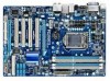
-UD3H Motherboard Layout KB_USB VGA_DVI ATX_12V LGA1156 PHASE LED HDMI OPTICAL ATX R_USB USB_LAN CPU_FAN IT8213 IT8720 AUDIO F_AUDIO PCIEX1 RTL8111D PCIEX16 PCI1 CODEC PCI2 SPDIF_O SPDIF_I CD_IN PCI3 PCI4 PCIEX4 COMA BAT GA-H55-UD3H DDR3_2 DDR3_1 DDR3_4 DDR3_3 PWR_FAN Intel - Gigabyte GA-H55-UD3H | Manual - Page 8
CLK (100 MHz) x16 PCI Express Bus 1 PCI Express x4 LAN PCIe CLK (100 MHz) RJ45 RTL8111D PCI Express Bus x4 x1 Intel® H55 FDI Interface DMI Interface D-Sub DVI-D or HDMI (Note) Dual BIOS 6 SATA 3Gb/s PCI Bus IT8213 12 USB 2.0/1.1 CODEC LPC Bus IT8720 Floppy COM Port PS/2 KB/Mouse ATA - Gigabyte GA-H55-UD3H | Manual - Page 9
's manual and follow these procedures: • Prior to installation, do not remove or break motherboard S/N wrist strap when handling electronic com- ponents such as a motherboard, CPU or memory. If you do not have an ESD wrist steps or have a problem related to the use of the product, please consult - Gigabyte GA-H55-UD3H | Manual - Page 10
in the LGA1156 package (Go to GIGABYTE's website for the latest CPU support list.) L3 cache varies with CPU Chipset Intel® H55 Express Chipset Memory Onboard Graphics Audio 4 x 1.5V DDR3 DIMM sockets supporting up to 16 GB of system memory - Gigabyte GA-H55-UD3H | Manual - Page 11
USB Chipset: - Up to 12 USB 2.0/1.1 ports (8 on the back panel, 4 via the USB brackets connected to the internal USB headers) Internal w 1 x 24-pin ATX main power connector Connectors w 1 x 4-pin ATX 12V power connector w 1 x floppy disk drive connector w 1 x - Gigabyte GA-H55-UD3H | Manual - Page 12
and HDMI ports, you must install an Intel CPU with integrated graphics. (Note 3) The DVI-D port does not support D-Sub connection by adapter. (Note 4) You can use only one of the onboard digital graphics ports (e.g. HDMI and DVI-D) for output when in the BIOS Setup program or when during the POST - Gigabyte GA-H55-UD3H | Manual - Page 13
hardware specifications including the CPU, graphics card, memory, hard drive, etc. 1-3-1 Installing the CPU A. Locate the alignment keys on the motherboard CPU socket and the notches on the CPU. LGA1156 CPU Socket Alignment Key Alignment Key Pin One Corner of the CPU Socket LGA1156 CPU Notch - Gigabyte GA-H55-UD3H | Manual - Page 14
B. Follow the steps below to correctly install the CPU into the motherboard CPU socket. Before installing the CPU, make sure to turn off the computer and unplug the power cord from the power outlet to prevent damage to the CPU. Step 1: Gently press the CPU socket lever handle down and away from the - Gigabyte GA-H55-UD3H | Manual - Page 15
pin. Check that the Male and Female push pins are joined closely. (Refer to your CPU cooler installation manual for instructions on installing the cooler.) Step 5: After the installation, check the back of the motherboard. If the push pin is inserted as the picture above shows, the installation is - Gigabyte GA-H55-UD3H | Manual - Page 16
motherboard provides four DDR3 memory sockets and supports Dual Channel Technology. After the memory is installed, the BIOS will automatically detect the specifications "- -"=No Memory) DDR3_2 DDR3_1 DDR3_4 DDR3_3 Due to CPU limitations, read the following guidelines before installing the memory in - Gigabyte GA-H55-UD3H | Manual - Page 17
to each other or DDR DIMMs. Be sure to install DDR3 DIMMs on this motherboard. Notch DDR3 DIMM A DDR3 memory module has a notch, so it can only Spread the retaining clips at both ends of the memory socket. Place the memory module on the socket. As indicated in the picture on the left, place - Gigabyte GA-H55-UD3H | Manual - Page 18
an expansion card: • Make sure the motherboard supports the expansion card. Carefully read the manual that came with your expansion card. • Always If necessary, go to BIOS Setup to make any required BIOS changes for your expansion card(s). 7. Install the driver provided with the expansion card - Gigabyte GA-H55-UD3H | Manual - Page 19
select Start>Control Panel>Sound, set Intel(R) Display Audio HDMI 2 to the default playback device. Dual Display Configurations for the Onboard Graphics: The table below shows the supported dual display configurations for the onboard graphics ports when in the BIOS Setup program or when during the - Gigabyte GA-H55-UD3H | Manual - Page 20
Refer to the instructions on setting up a 2/4/5.1/7.1-channel audio configuration in Chapter 5, "Configuring 2/4/5.1/7.1-Channel Audio." (Note 1) To use the onboard D-Sub, DVI-D and HDMI ports, you must install an Intel CPU with integrated graphics. (Note 2) The DVI-D port does not support D-Sub - Gigabyte GA-H55-UD3H | Manual - Page 21
2) ATX 3) CPU_FAN 4) SYS_FAN1/2 5) PWR_FAN 6) FDD 7) IDE 8) SATA2_0/1/2/3/4/5 9) F_PANEL 10) F_AUDIO 11) CD_IN 12) SPDIF_I 13) SPDIF_O 14) F_USB1/F_USB2 15) COMA 16) BAT 17) CLR_CMOS 18) PHASE LED Read has been securely attached to the connector on the motherboard. - 21 - Hardware Installation - Gigabyte GA-H55-UD3H | Manual - Page 22
ATX (2x2 12V Power Connector and 2x12 Main Power Connector) With the use of the power connector, the power supply can supply enough stable power to all the components on the motherboard . The 12V power connector mainly supplies power to the CPU. If the 12V power connector is not connected, the - Gigabyte GA-H55-UD3H | Manual - Page 23
connector wire is the ground wire). The motherboard supports CPU fan speed control, which requires the use of a CPU fan with fan speed control design. disk drive. The types of floppy disk drives supported are: 360 KB, 720 KB, 1.2 MB, 1.44 MB, and 2.88 MB. Before connecting a floppy disk drive, be - Gigabyte GA-H55-UD3H | Manual - Page 24
read the instructions from the device manufacturers.) 39 1 40 2 8) SATA2_0/1/2/3/4/5 (SATA 3Gb/s Connectors, Controlled by H55 Chipset) The SATA connectors conform to SATA 3Gb/s standard and are compatible with SATA 1.5Gb/s standard. Each SATA connector supports a - Gigabyte GA-H55-UD3H | Manual - Page 25
beep will be heard if no problem is detected at system startup. If a problem is detected, the BIOS may issue beeps in different patterns to indicate the problem. Refer to Chapter 5, "Troubleshooting," for information about beep codes. • HD (Hard Drive Activity LED, Blue) Connects to the hard drive - Gigabyte GA-H55-UD3H | Manual - Page 26
Header) The front panel audio header supports Intel High Definition audio (HD) and AC'97 audio. You may connect your chassis front panel audio module to this header. Make sure the wire assignments of the module connector match the pin assignments of the motherboard header. Incorrect connection - Gigabyte GA-H55-UD3H | Manual - Page 27
No. Definition 1 Power 2 SPDIFI 3 GND 13) SPDIF_O (S/PDIF Out Header) This header supports digital S/PDIF Out and connects a S/PDIF digital audio cable (provided by expansion cards) for digital audio output from your motherboard to certain expansion cards like graphics cards and sound cards. For - Gigabyte GA-H55-UD3H | Manual - Page 28
conform to USB 2.0/1.1 specification. Each USB header can provide two USB ports via an optional USB bracket. For purchasing the optional USB bracket, please contact the local dealer. Pin No. Definition 1 Power (5V) 9 1 2 Power (5V) 10 2 3 USB DX- 4 USB DY- 5 USB DX+ 6 USB DY+ 7 GND - Gigabyte GA-H55-UD3H | Manual - Page 29
the jumper. Failure to do so may cause damage to the motherboard. • After system restart, go to BIOS Setup to load factory defaults (select Load Optimized Defaults) or manually configure the BIOS settings (refer to Chapter 2, "BIOS Setup," for BIOS configurations). - 29 - Hardware Installation - Gigabyte GA-H55-UD3H | Manual - Page 30
18) PHASE LED The number of lighted LEDs indicates the CPU loading. The higher the CPU loading, the more the number of lighted LEDs. To enable the Phase LED display function, please first enable Dynamic Energy Saver™ 2. Refer to Chapter 4, "Dynamic Energy Saver™ 2," for more details. Hardware - Gigabyte GA-H55-UD3H | Manual - Page 31
latest version of BIOS from the Internet and updates the BIOS. For instructions on using the Q-Flash and @BIOS utilities, refer to Chapter 4, "BIOS Update Utilities." • Because BIOS flashing is potentially risky, if you do not encounter problems using the current version of BIOS, it is recommended - Gigabyte GA-H55-UD3H | Manual - Page 32
.00PG, An Energy Star Ally Copyright (C) 1984-2009, Award Software, Inc. Motherboard Model BIOS Version H55-UD3H E7 . . . . : BIOS Setup : XpressRecovery2 : Boot Menu : Qflash 11/16/2009-H55-7A89TG07C-00 Function Keys Function Keys Function Keys: : POST SCREEN Press the - Gigabyte GA-H55-UD3H | Manual - Page 33
BIOS Version: E7) CMOS Setup Utility-Copyright (C) 1984-2009 Award Software MB Intelligent Tweaker(M.I.T.) Standard CMOS Features Advanced BIOS Save & Exit Setup Change CPU's Clock & Voltage F11: Save CMOS to BIOS F12: Load CMOS from BIOS BIOS Setup Program Function Keys Move - Gigabyte GA-H55-UD3H | Manual - Page 34
. Advanced BIOS Features Use this menu to configure the device boot order, advanced features available on the CPU, and the primary display adapter. Integrated Peripherals Use this menu to configure all peripheral devices, such as IDE, SATA, USB, integrated audio, and integrated LAN, etc. Power - Gigabyte GA-H55-UD3H | Manual - Page 35
CPU Temperature PCH Temperature Vcore DRAM Voltage E7 133.27 MHz 3198.42 MHz 1332.80 MHz 1024 MB overall system configurations. Incorrectly doing overclock/overvoltage may result in damage to CPU, chipset, or memory and reduce the supports this feature. - 35 - BIOS Setup - Gigabyte GA-H55-UD3H | Manual - Page 36
to decrease power consumption. Auto lets the BIOS automatically configure this setting. (Default: Auto) (Note) This item is present only if you install a CPU that supports this feature. For more information about Intel CPUs' unique features, please visit Intel's website. BIOS Setup - 36 - - Gigabyte GA-H55-UD3H | Manual - Page 37
Important: It is highly recommended that the CPU frequency be set in accordance with the CPU specifications. (Note) This item is present only if you install a CPU that supports this feature. For more information about Intel CPUs' unique features, please visit Intel's website. - 37 - BIOS Setup - Gigabyte GA-H55-UD3H | Manual - Page 38
Express and Chipset clock. Options are: 700mV, 800mV, 900mV (default), 1000mV. CPU Clock Skew Allows you to set the CPU clock prior to the Chipset clock. Options are: 0ps~750ps. (Default: 0ps) (Note) This item appears only if you install a memory module that supports this feature. BIOS Setup - 38 - Gigabyte GA-H55-UD3H | Manual - Page 39
Help F7: Optimized Defaults Extreme Memory Profile (X.M.P.) (Note) Allows the BIOS to read the SPD data on XMP memory module(s) to enhance memory performance on the CPU being used. (Note) This item appears only if you install a memory module that supports this feature. - 39 - BIOS Setup - Gigabyte GA-H55-UD3H | Manual - Page 40
Options are: Auto (default), 1~10. tRFC Options are: Auto (default), 1~255. tRTP Options are: Auto (default), 1~15. ESC: Exit F1: General Help F7: Optimized Defaults BIOS Setup - 40 - - Gigabyte GA-H55-UD3H | Manual - Page 41
Enables or disables Load-Line Calibration. Enabling this feature adjusts Vdroop, keeping the CPU voltage more constant under light and heavy CPU load. Disabled sets the CPU voltage following Intel specifications. (Default: Disabled) Note: Enabling Load-Line Calibration may result in damage to your - Gigabyte GA-H55-UD3H | Manual - Page 42
Help F7: Optimized Defaults Isochronous Support Determines whether to enable specific streams within the CPU and Chipset. (Default: Enabled) Virtualization Technology (Note) Enables or disables Intel Virtualization Technology. Virtualization enhanced by Intel Virtualization Technology will allow - Gigabyte GA-H55-UD3H | Manual - Page 43
133.27 MHz 3198.42 MHz 1332.80 MHz 1024 MB CPU Temperature PCH Temperature 45oC 40oC Vcore DRAM Voltage 1.264V 1. provides information on the BIOS version, CPU base clock, CPU frequency, memory frequency, total memory size , CPU temperature, Chipset temperature, Vcore, and - Gigabyte GA-H55-UD3H | Manual - Page 44
Mode Lets the BIOS automatically detect IDE/SATA devices during the POST. (Default) If no IDE/SATA devices are used, set this item to None so the system will skip the detection of the device during the POST for faster system startup. Allows you to manually enter the specifications of the hard - Gigabyte GA-H55-UD3H | Manual - Page 45
following fields display your hard drive specifications. If you wish to enter the parameters manually, refer to the information on the all other errors. Memory These fields are read-only and are determined by the BIOS POST. Base Memory Also called conventional memory. Typically, 640 KB will be - Gigabyte GA-H55-UD3H | Manual - Page 46
Default) System A password is required for booting the system and for entering the BIOS Setup program. (Note) This item is present only if you install a CPU that supports this feature. For more information about Intel CPUs' unique features, please visit Intel's website. BIOS Setup - 46 - - Gigabyte GA-H55-UD3H | Manual - Page 47
display. Options are: 32MB+2MB for GTT, 64MB+2MB for GTT (default), 128MB+2MB for GTT. (Note) This item is present only if you install a CPU that supports this feature. For more information about Intel CPUs' unique features, please visit Intel's website. - 47 - BIOS Setup - Gigabyte GA-H55-UD3H | Manual - Page 48
integrated in the Intel H55 Chipset to AHCI mode. IDE Configures the SATA controller to IDE mode. (Default) AHCI Configures the SATA controller to AHCI mode. Advanced Host Controller Interface (AHCI) is an interface specification that allows the storage driver to enable advanced Serial - Gigabyte GA-H55-UD3H | Manual - Page 49
LAN cable is attached to the motherboard, the Status fields of all four pairs of wires will show Open and the Length fields show 0m, as shown in the figure above. When LAN Cable Is Functioning Normally... If no cable problem is detected on the LAN of the attached LAN cable. - 49 - BIOS Setup - Gigabyte GA-H55-UD3H | Manual - Page 50
Boot ROM Allows you to decide whether to activate the boot ROM integrated with the onboard LAN chip. (Default: Disabled) Onboard IDE Controller (iTE IT8213 Chip) Enables or disables the IDE controller . Options are: Auto, 3F8/IRQ4 (default), 2F8/IRQ3, 3E8/IRQ4, 2E8/IRQ3, Disabled. BIOS Setup - 50 - - Gigabyte GA-H55-UD3H | Manual - Page 51
RAM) wake-up signal from a modem that supports wake-up function. (Default: Enabled) Resume by Alarm Determines whether to power on the system at a desired time. (Default: Disabled) If enabled, set the date and time as following: (Note) Supported on Windows 7/Vista operating system only. - 51 - BIOS - Gigabyte GA-H55-UD3H | Manual - Page 52
system at a specific time on each day or on a specific day in be turned on by a PS/2 keyboard wake-up event. Note: you need an ATX power supply providing at least 1A on wake up, power on by mouse, power on by keyboard, and wake on LAN. (Note) Supported on Windows 7/Vista operating system only. BIOS - Gigabyte GA-H55-UD3H | Manual - Page 53
device attached to the motherboard CI header. If CPU Temperature Displays current system/CPU temperature. Current CPU/SYSTEM FAN Speed (RPM) Displays current CPU/system fan speed. CPU Warning Temperature Sets the warning threshold for CPU temperature. When CPU temperature exceeds the threshold, BIOS - Gigabyte GA-H55-UD3H | Manual - Page 54
a 3-pin CPU fan. PWM Sets PWM mode for a 4-pin CPU fan. Note: The Voltage mode can be set for a 3-pin CPU fan or a 4-pin CPU fan. However, for a 4-pin CPU fan that is not designed following Intel PWM fan specifications, selecting PWM mode may not effectively reduce the fan speed. BIOS Setup - 54 - Gigabyte GA-H55-UD3H | Manual - Page 55
to load Fail-Safe defaults, which are the safest and most stable BIOS settings for the motherboard. 2-10 Load Optimized Defaults CMOS Setup Utility-Copyright (C) 1984-2009 Award Software MB Intelligent Tweaker(M.I.T.) Load Fail-Safe Defaults Standard CMOS Features Load Optimized Defaults - Gigabyte GA-H55-UD3H | Manual - Page 56
2-11 Set Supervisor/User Password CMOS Setup Utility-Copyright (C) 1984-2009 Award Software MB Intelligent Tweaker(M.I.T.) Standard CMOS Features Advanced BIOS Features Integrated Peripherals Power Management SetupEnter Password: PC Health Status Load Fail-Safe Defaults Load Optimized - Gigabyte GA-H55-UD3H | Manual - Page 57
2-12 Save & Exit Setup CMOS Setup Utility-Copyright (C) 1984-2009 Award Software MB Intelligent Tweaker(M.I.T.) Load Fail-Safe Defaults Standard CMOS Features Advanced BIOS Features Load Optimized Defaults Save to CMOS and EXITSe(Yt S/Nup)?erYvisor Password Integrated Peripherals Set - Gigabyte GA-H55-UD3H | Manual - Page 58
BIOS Setup - 58 - - Gigabyte GA-H55-UD3H | Manual - Page 59
are installed, follow the on-screen instructions to restart your system. You can install other applications included in the motherboard driver disk. • For USB 2.0 driver support under the Windows XP operating system, please install the Windows XP Service Pack 1 or later. After installing the SP1 - Gigabyte GA-H55-UD3H | Manual - Page 60
applications that GIGABYTE develops and some free software. You can click the Install button on the right of an item to install it. 3-3 Technical Manuals This page provides GIGABYTE's application guides, content descriptions for this driver disk, and the motherboard manuals. Drivers Installation - Gigabyte GA-H55-UD3H | Manual - Page 61
3-4 Contact For the detailed contact information of the GIGABYTE Taiwan headquarter or worldwide branch offices, click the URL on this page to link to the GIGABYTE website. 3-5 System This page provides the basic system information. - 61 - Drivers Installation - Gigabyte GA-H55-UD3H | Manual - Page 62
, or applications, click the Download Center button to link to the GIGABYTE website. The latest version of the BIOS, drivers, or applications will be displayed. 3-7 New Utilities This page provides a quick link to GIGABYTE's lately developed utilities for users to install. You can click the Install - Gigabyte GA-H55-UD3H | Manual - Page 63
up your system soon after the operating system and drivers are installed. • The amount of data and hard to restore it. System Requirements: • At least 512 MB of system memory • VESA compatible graphics card • Windows USB hard drives are not supported. • Hard drives in RAID/AHCI mode are not supported - Gigabyte GA-H55-UD3H | Manual - Page 64
note that if there is no enough unallocated space, Xpress Recovery2 cannot save the backup file. B. Accessing Xpress Recovery2 1. Boot from the motherboard driver disk to access Xpress Recovery2 for the first time. When you see the following message: Press any key to startup Xpress Recovery2, press - Gigabyte GA-H55-UD3H | Manual - Page 65
D. Using the Restore Function in Xpress Recovery2 Select RESTORE to restore the backup to your hard drive in case the system breaks down. The RESTORE option will not be present if no backup is created before. E. Removing the Backup Step 1: If you wish to remove the backup file, select REMOVE. Step - Gigabyte GA-H55-UD3H | Manual - Page 66
. However, if the BIOS update file is saved to a hard drive in RAID/AHCI mode or a hard drive attached to an independent IDE/SATA controller, use the key during the POST to access Q-Flash. Award Modular BIOS v6.00PG, An Energy Star Ally Copyright (C) 1984-2009, Award Software, Inc. H55-UD3H E7 - Gigabyte GA-H55-UD3H | Manual - Page 67
key to select Update BIOS from Drive and press . • The Save Main BIOS to Drive option allows you to save the current BIOS file. • Q-Flash only supports USB flash drive or hard drives using FAT32/16/12 file system. • If the BIOS update file is saved to a hard drive in RAID/AHCI mode or a hard - Gigabyte GA-H55-UD3H | Manual - Page 68
Optimized Defaults and press to load BIOS defaults. System will re-detect all peripheral devices after a BIOS update, so we recommend that you reload BIOS defaults. CMOS Setup Utility-Copyright (C) 1984-2009 Award Software MB Intelligent Tweaker(M.I.T.) Standard CMOS Features Advanced - Gigabyte GA-H55-UD3H | Manual - Page 69
. If the BIOS update file for your motherboard is not present on the @BIOS server site, please manually download the BIOS update file from GIGABYTE's website and follow the instructions in "Update the BIOS without Using the Internet Update Function" below. 2. Update the BIOS without Using the - Gigabyte GA-H55-UD3H | Manual - Page 70
functions in EasyTune 6 may differ by motherboard model. Grayed-out area(s) indicates that the item is not configurable or the function is not supported. Incorrectly doing overclock/overvoltage may result in damage to the hardware components such as CPU, chipset, and memory and reduce the useful - Gigabyte GA-H55-UD3H | Manual - Page 71
Phase LED On/Off Switch (Default: On) 16 Live Utility Update (Check for the latest utility version) • The above data is for reference only. Actual performance may vary depending on motherboard model. • CPU Power and Power Scores are for reference only. Actual results may vary based on testing - Gigabyte GA-H55-UD3H | Manual - Page 72
INFO/Help 14 Motherboard Phase LED On/Off Switch (Default: On) 15 Live Utility Update (Check for the CPU Enhanced Halt (C1E) and CPU EIST Function items in the BIOS Setup program are set to Enabled. (Note 2) 1: Smart FAN/CPU (default); 2: Smart FAN/CPU/VGA/HDD; 3: Smart FAN/CPU/VGA/HDD/Chipset - Gigabyte GA-H55-UD3H | Manual - Page 73
configuring your LAN connection settings and Q-Share, you are able to share your data with computers on the same network, making full use of Internet resources. Directions for using Q-Share After installing Q-Share from the motherboard driver disk, go to Start>All Programs>GIGABYTE>Q-Share. exe - Gigabyte GA-H55-UD3H | Manual - Page 74
4-6 Smart 6™ GIGABYTE Smart 6™ (Note 1) is designed with user-friendliness in CPU overclocking for novice and experienced users alike; users simply click on one of the three levels of CPU performance enhancement, and SMART QuickBoost automatically adjusts CPU performance. Instructions: Select a CPU - Gigabyte GA-H55-UD3H | Manual - Page 75
Recovery, users can quickly create backups of changed data files (Note 2) or copy files from a specific backup on PATA and SATA hard drives (partitioned on NTFS file system) in Windows Vista. Instructions: In the main menu, click the Config button to open the Smart Recovery Preference dialog box - Gigabyte GA-H55-UD3H | Manual - Page 76
within the hard drive or copied to an external storage device (Note 5). Instructions: Select the Enable check box at the bottom of the ON/OFF users to effectively manage computer usage time with simple rules and options. Instructions (Note 6): Click the lock icon on the bottom left corner and - Gigabyte GA-H55-UD3H | Manual - Page 77
detected, the system will enter the selected energy saving mode. • Turn off HD: Set when to turn off the hard drive. If the system inactivity time RAM mode Disables this function The Bluetooth dongle included in the motherboard package(Note 2) allows you to wake up the system from Suspend to RAM - Gigabyte GA-H55-UD3H | Manual - Page 78
Unique Features - 78 - - Gigabyte GA-H55-UD3H | Manual - Page 79
jack and manually configure the jack for microphone functionality. • Audio signals will be present on both of the front and back panel audio connections simultaneously. If you want to mute the back panel audio (only supported when using an HD front panel audio module), refer to instructions on the - Gigabyte GA-H55-UD3H | Manual - Page 80
the Connector Settings dialog box, select the Disable front panel jack detection check box. Click OK to complete. D. Muting the Back Panel Audio (For HD Audio Only) Click Device advanced settings on the top right corner on the Speaker Configuration tab to open the Device advanced settings dialog box - Gigabyte GA-H55-UD3H | Manual - Page 81
allows you to input digital audio signals to the computer for audio processing. S/PDIF In Cable Optical S/PDIF In Coaxial S/PDIF In 1. Installing the S/PDIF In Cable: Step 1: First, attach the connector at the end of the cable to the SPDIF_I header on your motherboard. Step 2: Secure the metal - Gigabyte GA-H55-UD3H | Manual - Page 82
and bit depth. Click OK to complete. (Note) If you have connected a S/PDIF digital audio cable (provided by expansion cards) to the 2-pin S/PDIF Out header (SPDIF_O) on the motherboard to output digital audio to your expansion card, you can enter the Digital Output(Optical)j screen to - Gigabyte GA-H55-UD3H | Manual - Page 83
5-1-3 Configuring Microphone Recording Step 1: After installing the audio driver, the HD Audio Manager icon will appear in the notification area. Double-click the icon to access the HD Audio Manager. Step 2: Connect your microphone to the Mic in jack (pink) on the back panel or the Mic in jack (pink - Gigabyte GA-H55-UD3H | Manual - Page 84
, click Start, point to All Programs, point to Accessories, and then click Sound Recorder to begin the sound recording. * Enabling Stereo Mix If the HD Audio Manager does not display the recording device you wish to use, refer to the steps below. The following steps explain how to enable Stereo Mix - Gigabyte GA-H55-UD3H | Manual - Page 85
Step 4: Now you can access the HD Audio Manager to configure Stereo Mix and use audio, click the Stop Recording button . Be sure to save the recorded audio file upon completion. B. Playing the Recorded Sound You can play your recording in a digital media player program that supports your audio - Gigabyte GA-H55-UD3H | Manual - Page 86
the motherboard driver disk or download the audio driver from GIGABYTE's website to install. For more details, go to the Support&Downloads\Motherboards\FAQ page on our website and search for "onboard HD audio driver." Q: What do the beeps emitted during the POST mean? A: The following Award BIOS - Gigabyte GA-H55-UD3H | Manual - Page 87
the CPU cooler power cable to the motherboard. Yes The problem is verified and solved. Check if the memory is installed properly on the memory slot. No Correctly insert the memory into the memory socket. Yes The problem is verified and solved. Insert the graphics card. Connect the ATX - Gigabyte GA-H55-UD3H | Manual - Page 88
and solved. END If the procedure above is unable to solve your problem, contact the place of purchase or local dealer for help. Or go to the Support&Downloads\Technical Service Zone page to submit your question. Our customer service staff will reply you as soon as possible. Appendix - 88 - - Gigabyte GA-H55-UD3H | Manual - Page 89
GIGABYTE. Our Commitment to Preserving the Environment In addition to high-efficiency performance, all GIGABYTE motherboards local government office, your household waste disposal service or where you purchased the product for user's manual and we will be glad to help you with your effort. - - Gigabyte GA-H55-UD3H | Manual - Page 90
Finally, we suggest that you practice other environmentally friendly actions by understanding and using the energy-saving features of this product (where applicable), recycling the inner and outer packaging (including shipping containers) this product was delivered in, and by disposing of or - Gigabyte GA-H55-UD3H | Manual - Page 91
- 91 - Appendix - Gigabyte GA-H55-UD3H | Manual - Page 92
Appendix - 92 - - Gigabyte GA-H55-UD3H | Manual - Page 93
- 93 - Appendix - Gigabyte GA-H55-UD3H | Manual - Page 94
Appendix - 94 - - Gigabyte GA-H55-UD3H | Manual - Page 95
231, Taiwan TEL: +886-2-8912-4000 FAX: +886-2-8912-4003 Tech. and Non-Tech. Support (Sales/Marketing) : http://ggts.gigabyte.com.tw WEB address (English): http://www.gigabyte.com.tw WEB address (Chinese): http://www.gigabyte.tw • G.B.T. INC. - U.S.A. TEL: +1-626-854-9338 FAX: +1-626-854-9339 Tech - Gigabyte GA-H55-UD3H | Manual - Page 96
website, select your language in the language list on the top right corner of the website. • GIGABYTE Global Service System To submit a technical or non-technical (Sales/Marketing) question, please link to: http://ggts.gigabyte.com.tw Then select your language to enter the system. Appendix - 96 -
-
 1
1 -
 2
2 -
 3
3 -
 4
4 -
 5
5 -
 6
6 -
 7
7 -
8
-
9
-
10
-
11
-
12
-
13
-
14
-
15
-
16
-
17
-
18
-
19
-
20
-
21
-
22
-
23
-
24
-
25
-
26
-
27
-
28
-
29
-
30
-
31
-
32
-
33
-
34
-
35
-
36
-
37
-
38
-
39
-
40
-
41
-
42
-
43
-
44
-
45
-
46
-
47
-
48
-
49
-
50
-
51
-
52
-
53
-
54
-
55
-
56
-
57
-
58
-
59
-
60
-
61
-
62
-
63
-
64
-
65
-
66
-
67
-
68
-
69
-
70
-
71
-
72
-
73
-
74
-
75
-
76
-
77
-
78
-
79
-
80
-
81
-
82
-
83
-
84
-
85
-
86
-
87
-
88
-
89
-
90
-
91
-
92
-
93
-
94
-
95
-
96
 |
 |

GA-H55-UD3H
LGA1156 socket motherboard for Intel
®
Core
™
i7 processor family/
Intel
®
Core
™
i5 processor family/ Intel
®
Core
™
i3 processor family
User's Manual
Rev. 1001
12ME-H55UD3H-1001R