Gigabyte GA-H55-USB3 Manual
Gigabyte GA-H55-USB3 Manual
 |
UPC - 818313010032
View all Gigabyte GA-H55-USB3 manuals
Add to My Manuals
Save this manual to your list of manuals |
Gigabyte GA-H55-USB3 manual content summary:
- Gigabyte GA-H55-USB3 | Manual - Page 1
GA-H55-USB3 LGA1156 socket motherboard for Intel® Core™ i7 processor family/ Intel® Core™ i5 processor family/ Intel® Core™ i3 processor family User's Manual Rev. 1001 12ME-H55USB3-1001R - Gigabyte GA-H55-USB3 | Manual - Page 2
Motherboard GA-H55-USB3 Feb. 5, 2010 Motherboard GA-H55-USB3 Feb. 5, 2010 - Gigabyte GA-H55-USB3 | Manual - Page 3
the product. For detailed product information, carefully read the User's Manual. For instructions on how to use GIGABYTE's unique features, read or download the information on/from the Support&Downloads\Motherboard\Technology Guide page on our website. For product-related information, check on our - Gigabyte GA-H55-USB3 | Manual - Page 4
-USB3 Motherboard Layout 7 GA-H55-USB3 Motherboard Block Diagram 8 Chapter 1 Hardware Installation 9 1-1 Installation Precautions 9 1-2 Product Specifications 10 1-3 Installing the CPU and CPU Cooler 13 1-3-1 Installing the CPU 13 1-3-2 Installing the CPU Cooler 15 1-4 Installing the Memory - Gigabyte GA-H55-USB3 | Manual - Page 5
61 3-1 Installing Chipset Drivers 61 3-2 Application Software 62 3-3 Technical Manuals 62 3-4 Contact...63 3-5 System...63 3-6 Download Center 64 3-7 New Utilities...64 Chapter 4 Unique Features 65 4-1 Xpress Recovery2 65 4-2 BIOS Update Utilities 68 4-2-1 Updating the BIOS with the Q-Flash - Gigabyte GA-H55-USB3 | Manual - Page 6
Box Contents GA-H55-USB3 motherboard Motherboard driver disk User's Manual Quick Installation Guide One IDE cable Two SATA 3Gb/s cables I/O Shield • The box contents above are for reference only and the actual items shall depend on the product - Gigabyte GA-H55-USB3 | Manual - Page 7
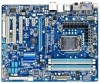
GA-H55-USB3 Motherboard Layout KB_USB CPU_FAN VGA_DVI ATX_12V_2X4 LGA1156 PHASE LED DP_HDMI_SPDIF ESATA_1394_USB USB30_LAN NEC D720200F1 AUDIO F_AUDIO PCIEX1_1 RTL8111D PCIEX16 PCIEX1_2 PCI2 CODEC PCIEX1_3 SPDIF_O CD_IN PCI1 SPDIF_I PCI2 IT8720 PCI3 ATX PWR_FAN GA-H55-USB3 - Gigabyte GA-H55-USB3 | Manual - Page 8
GA-H55-USB3 Motherboard Block Diagram 1 PCI Express x16 CPU CLK+/- (133 MHz) PCIe CLK (100 MHz) LGA1156 CPU DDR3 1666 (O.C.)/1333/1066/800 MHz Dual Channel Memory DMI Interface FDI Interface PCI Express Bus LAN RJ45 x16 x1 Gen 2 2 USB 3.0 RTL8111D Switch x1 Gen 1 NEC D720200F1 PCI Express - Gigabyte GA-H55-USB3 | Manual - Page 9
or memory. If you do not have an ESD wrist strap, keep your hands dry and first touch a metal object to eliminate static electricity. • Prior to installing the motherboard, please have it on top of an antistatic pad or within an electrostatic shielding container. • Before unplugging the power supply - Gigabyte GA-H55-USB3 | Manual - Page 10
Specifications CPU w w Support for an Intel® Core™ i7 series processor/Intel® Core™ i5 series processor/ Intel® Core™ i3 series processor in the LGA1156 package (Go to GIGABYTE's website for the latest CPU support list.) L3 cache varies with CPU Chipset Intel® H55 Express Chipset Memory - Gigabyte GA-H55-USB3 | Manual - Page 11
IEEE 1394a header) Internal w 1 x 24-pin ATX main power connector Connectors w 1 x 8-pin ATX 12V power connector w 1 x floppy disk drive connector w 1 x IDE connector w 7 x SATA 3Gb/s connectors w 1 x CPU fan header w 2 x system fan headers w 1 x front - Gigabyte GA-H55-USB3 | Manual - Page 12
Security (OEM version) Operating System w Support for Microsoft® Windows® 7/Vista/XP Form Factor w ATX Form Factor; 30.5cm x 24.4cm (Note 1) Due to Windows 32-bit operating system limitation, when more than 4 GB of physical memory is installed, the actual memory size displayed will be less than - Gigabyte GA-H55-USB3 | Manual - Page 13
before you begin to install the CPU: • Make sure that the motherboard supports the CPU. (Go to GIGABYTE's website for the latest CPU support list.) • Always turn off the computer and unplug the power cord from the power outlet before installing the CPU to prevent hardware damage. • Locate the - Gigabyte GA-H55-USB3 | Manual - Page 14
B. Follow the steps below to correctly install the CPU into the motherboard CPU socket. Before installing the CPU, make sure to turn off the computer and unplug the power cord from the power outlet to prevent damage to the CPU. Step 1: Gently press the CPU socket lever handle down and away from the - Gigabyte GA-H55-USB3 | Manual - Page 15
installation manual for instructions on installing the cooler.) Step 5: After the installation, check the back of the motherboard. If the push pin is inserted as the picture above shows, the installation is complete. Step 6: Finally, attach the power connector of the CPU cooler to the CPU fan - Gigabyte GA-H55-USB3 | Manual - Page 16
Make sure that the motherboard supports the memory. It is recommended that memory of the same capacity, brand, speed, and chips be used. (Go to GIGABYTE's website for the latest memory support list.) • Always turn off the computer and unplug the power cord from the power outlet before installing the - Gigabyte GA-H55-USB3 | Manual - Page 17
to turn off the computer and unplug the power cord from the power outlet to prevent damage to the memory module. DDR3 and DDR2 DIMMs are not compatible to each other or DDR DIMMs. Be sure to install DDR3 DIMMs on this motherboard. Notch DDR3 DIMM A DDR3 memory module has a notch, so it can only fit - Gigabyte GA-H55-USB3 | Manual - Page 18
motherboard supports the expansion card. Carefully read the manual that came with your expansion card. • Always turn off the computer and unplug the power cord from the power , go to BIOS Setup to make any required BIOS changes for your expansion card(s). 7. Install the driver provided with the - Gigabyte GA-H55-USB3 | Manual - Page 19
. Refer to the figure below for details.) • Please note the HDMI audio output only supports AC3, DTS and 2-channel-LPCM formats. (AC3 and DTS require the use of an external decoder for decoding.) In Windows Vista, select Start>Control Panel>Sound> Playback, set Intel(R) Display Audio HDMI 2 to the - Gigabyte GA-H55-USB3 | Manual - Page 20
The table below shows the supported dual display configurations for the onboard graphics ports when in the BIOS Setup program or when during and D-Sub ports, you must install an Intel CPU with integrated graphics. (Note 2) The DVI-D port does not support D-Sub connection by adapter. (Note 3) You - Gigabyte GA-H55-USB3 | Manual - Page 21
USB 3.0 port supports the USB 3.0 specification and is compatible to the USB Mic in jack ( ). Refer to the instructions on setting up a 2/4/5.1/7.1-channel audio configuration in the cable from your device and then remove it from the motherboard. • When removing the cable, pull it straight out from - Gigabyte GA-H55-USB3 | Manual - Page 22
13 14 17 18 6 2 8 9 7 4 16 4 19 11 1) ATX_12V_2X4 2) ATX 3) CPU_FAN 4) SYS_FAN1/SYS_FAN2 5) PWR_FAN 6) FDD 7) IDE 8) SATA2_0/1/2/3/4 9) GSATA2_5/6 10) to turn off the devices and your computer. Unplug the power cord from the power outlet to prevent damage to the devices. • After installing the - Gigabyte GA-H55-USB3 | Manual - Page 23
1/2) ATX_12V_2X4/ATX (2x4 12V Power Connector and 2x12 Main Power Connector) With the use of the power connector, the power supply can supply enough stable power to all the components on the motherboard. Before connecting the power connector, first make sure the power supply is turned off and all - Gigabyte GA-H55-USB3 | Manual - Page 24
power fan. Most fan headers possess a foolproof insertion design. When connecting a fan cable, be sure to connect it in the correct orientation (the black connector wire is the ground wire). The motherboard supports CPU disk drives supported are: 360 KB, 720 KB, 1.2 MB, 1.44 MB, and 2.88 MB. Before - Gigabyte GA-H55-USB3 | Manual - Page 25
IDE devices, read the instructions from the device manufacturers.) 40 39 2 1 8) SATA2_0/1/2/3/4 (SATA 3Gb/s Connectors, Controlled by H55 Chipset) The SATA connectors conform to SATA 3Gb/s standard and are compatible with SATA 1.5Gb/s standard. Each SATA connector supports a single SATA device - Gigabyte GA-H55-USB3 | Manual - Page 26
to SATA 3Gb/s standard and are compatible with SATA 1.5Gb/s standard. Each SATA connector supports a single SATA device. The GIGABYTE SATA2 controller supports RAID 0 and RAID 1. Refer to Chapter 5, "Configuring SATA Hard Drive(s)," for instructions on configuring a RAID array. G.QBOFM Pin No - Gigabyte GA-H55-USB3 | Manual - Page 27
problem is detected at system startup. If a problem is detected, the BIOS may issue beeps in different patterns to indicate the problem. Refer to Chapter 5, "Troubleshooting chassis. A front panel module mainly consists of power switch, reset switch, power LED, hard drive activity LED, speaker and - Gigabyte GA-H55-USB3 | Manual - Page 28
MIC Power 4 -ACZ_DET 4 NC 5 LINE2_R 5 Line Out (R) 6 GND 6 NC 7 FAUDIO_JD 7 NC 8 No Pin 8 No Pin 9 LINE2_L 9 Line Out (L) 10 GND 10 NC • The front panel audio header supports HD audio by default. If your chassis provides an AC'97 front panel audio module, refer to the instructions on - Gigabyte GA-H55-USB3 | Manual - Page 29
Power 2 SPDIFI 3 GND 15) SPDIF_O (S/PDIF Out Header) This header supports digital S/PDIF Out and connects a S/PDIF digital audio cable (provided by expansion cards) for digital audio output from your motherboard carefully read the manual for your expansion card. Pin No. Definition 1 1 - Gigabyte GA-H55-USB3 | Manual - Page 30
can provide two USB ports via an optional USB bracket. For purchasing the optional USB bracket, please contact the local dealer. Pin No. Definition 1 Power (5V) 2 Power (5V) 9 1 10 2 3 USB DX- G.QBOF4M USB DY- 5 USB DX+ 6 USB DY+ 7 GND 8 GND 9 No Pin 10 NC • Do not plug the IEEE 1394 - Gigabyte GA-H55-USB3 | Manual - Page 31
date information and BIOS configurations) and reset the CMOS the power cord from the power outlet before motherboard. • After system restart, go to BIOS Setup to load factory defaults (select Load Optimized Defaults) or manually configure the BIOS settings (refer to Chapter 2, "BIOS Setup," for BIOS - Gigabyte GA-H55-USB3 | Manual - Page 32
20) PHASE LED The number of lighted LEDs indicates the CPU loading. The higher the CPU loading, the more the number of lighted LEDs. To enable the Phase LED display function, please first enable Dynamic Energy Saver™ 2. Refer to Chapter 4, "Dynamic - Gigabyte GA-H55-USB3 | Manual - Page 33
the GIGABYTE Q-Flash or @BIOS utility. • Q-Flash allows the user to quickly and easily upgrade or back up BIOS without entering the operating system. • @BIOS is a Windows-based utility that searches and downloads the latest version of BIOS from the Internet and updates the BIOS. For instructions on - Gigabyte GA-H55-USB3 | Manual - Page 34
v6.00PG, An Energy Star Ally Copyright (C) 1984-2009, Award Software, Inc. Motherboard Model BIOS Version H55-USB3 E4 . . . . : BIOS Setup : XpressRecovery2 : Boot Menu : Qflash 01/10/2010-H55-7A89TG0TC-00 Function Keys Function Keys SATA Mode Message: "SATA is found running - Gigabyte GA-H55-USB3 | Manual - Page 35
BIOS Version: E4) CMOS Setup Utility-Copyright (C) 1984-2009 Award Software MB Intelligent Tweaker(M.I.T.) Standard CMOS Features Advanced BIOS Features Integrated Peripherals Power Setup Change CPU's Clock & Voltage F11: Save CMOS to BIOS F12: Load CMOS from BIOS BIOS Setup Program - Gigabyte GA-H55-USB3 | Manual - Page 36
before, without the hassles of reconfiguring the BIOS settings. First select the profile you wish to load, then press to complete. MB Intelligent Tweaker(M.I.T.) Use this menu to configure the clock, frequency and voltages of your CPU, memory, etc. Standard CMOS Features Use this menu - Gigabyte GA-H55-USB3 | Manual - Page 37
BIOS Version BCLK CPU Frequency Memory Frequency Total Memory Size E4 133.37 MHz 3067.78 MHz 1333.75 MHz 1024 MB CPU reset the board to default values.) M.I.T. Current Status This screen provides information on CPU/memory if you install a CPU that supports this feature. For - Gigabyte GA-H55-USB3 | Manual - Page 38
and voltage will be reduced during system halt state to decrease power consumption. Auto lets the BIOS automatically configure this setting. (Default: Auto) (Note) This item is present only if you install a CPU that supports this feature. For more information about Intel CPUs' unique features - Gigabyte GA-H55-USB3 | Manual - Page 39
, please wait for 20 seconds to allow for automated system reboot, or clear the CMOS values to reset the board to default values. (Default: Disabled) BCLK Frequency(Mhz) Allows you to manually set the CPU base clock. The adjustable range is from 100 MHz to 600 MHz. This item is configurable only - Gigabyte GA-H55-USB3 | Manual - Page 40
set the CPU clock prior to the Chipset clock. Options are: 0ps~750ps. (Default: 0ps) IOH Clock Skew Allows you to set the Chipset clock prior to the CPU clock. Options are: 0ps~750ps. (Default: 0ps) (Note) This item appears only if you install a memory module that supports this feature. BIOS Setup - Gigabyte GA-H55-USB3 | Manual - Page 41
is set to Profile1 or Profile2, this item will display the value based on the SPD data on the XMP memory. Profile QPI Voltage The value displayed here is dependent on the CPU being used. (Note) This item appears only if you install a memory module that supports this feature. - 41 - BIOS Setup - Gigabyte GA-H55-USB3 | Manual - Page 42
Options are: Auto (default), 1~31. tWL Options are: Auto (default), 1~10 tRFC Options are: Auto (default), 1~255. ESC: Exit F1: General Help F7: Optimized Defaults BIOS Setup - 42 - - Gigabyte GA-H55-USB3 | Manual - Page 43
disables Load-Line Calibration. Enabling this feature adjusts Vdroop, keeping the CPU voltage more constant under light and heavy CPU load. Disabled sets the CPU voltage following Intel specifications. Auto lets the BIOS automatically configure this setting. (Default: Auto) Note: Enabling Load-Line - Gigabyte GA-H55-USB3 | Manual - Page 44
is Auto. CPU PLL The 2009 Award Software Miscellaneous Settings Isochronous Support Virtualization Technology (Note) [Enabled Support Determines whether to enable specific streams within the CPU and Chipset. (Default: Enabled) (Note) This item is present only if you install a CPU that supports - Gigabyte GA-H55-USB3 | Manual - Page 45
This section provides information on the BIOS version, CPU base clock, CPU frequency, memory frequency, total memory size , CPU temperature, Chipset temperature, Vcore, and memory voltage. (Note) This item is present only if you install a CPU that supports this feature. For more information about - Gigabyte GA-H55-USB3 | Manual - Page 46
Setup Utility-Copyright (C) 1984-2009 Award Software Standard CMOS Features Extended Memory Total Memory 827M 832M Item Help Menu Level Move Enter: Select F5: of the three methods below: • Auto Lets the BIOS automatically detect IDE/SATA devices during the POST. (Default - Gigabyte GA-H55-USB3 | Manual - Page 47
the device during the POST for faster system startup. • Manual Allows you to manually enter the specifications of the hard drive when the hard other errors. Memory These fields are read-only and are determined by the BIOS POST. Base Memory Also called conventional memory. Typically, 640 - Gigabyte GA-H55-USB3 | Manual - Page 48
Execute Memory Protect (Note) Delay For HDD (Secs) Full Screen LOGO Show Backup BIOS (or ) to move it up or down on the list. Press to exit this menu when finished. Quick Boot Enables only if you install a CPU that supports this feature. For more information about Intel CPUs - Gigabyte GA-H55-USB3 | Manual - Page 49
for Windows XP operating system; set this item to Enabled for legacy operating system such as Windows NT4.0. (Default: Disabled) No-Execute Memory working with its supporting software and system. (Default: Enabled) Delay For HDD (Secs) Allows you to set a delay time for the BIOS to initialize the - Gigabyte GA-H55-USB3 | Manual - Page 50
driver to enable advanced Serial ATA features such as Native Command Queuing and hot plug. SATA Port0-3 Native Mode (Intel H55 if you wish to install operating systems that do not support Native mode. Enabled Allows the SATA controllers to operate in Enabled) BIOS Setup - 50 - - Gigabyte GA-H55-USB3 | Manual - Page 51
F7: Optimized Defaults This motherboard incorporates cable diagnostic feature LAN cable is attached to the motherboard, the Status fields of all four Cable Is Functioning Normally... If no cable problem is detected on the LAN cable connected Windows mode or when the LAN Boot ROM is activated. - 51 - Gigabyte GA-H55-USB3 | Manual - Page 52
or disables the IDE and SATA controllers integrated in the GIGABYTE SATA2 chip. (Default: Enabled) Onboard SATA/IDE Ctrl Mode (GIGABYTE SATA2, GSATA2_5/6 Connectors) Enables or disables RAID for the SATA controller integrated in the GIGABYTE SATA2 chip or configures the SATA controller to AHCI mode - Gigabyte GA-H55-USB3 | Manual - Page 53
, you need an ATX power supply providing at least 1A on the +5VSB lead. (Default: Enabled) Power On by Ring Allows the system to be awakened from an ACPI sleep state by a wake-up signal from a modem that supports wake-up function. (Default: Enabled) (Note) Supported on Windows 7/Vista operating - Gigabyte GA-H55-USB3 | Manual - Page 54
when you install 64-bit Windows 7/Vista. This item is configurable only if the HPET Support is set to Enabled. (Default: 32-bit mode) Power On By Mouse Allows the system to be turned on by a PS/2 mouse wake-up event. Note: To use this function, you need an ATX power supply providing at least 1A - Gigabyte GA-H55-USB3 | Manual - Page 55
the motherboard CI set Reset Case CPU Temperature Displays current system/CPU temperature. Current CPU/SYSTEM/POWER FAN Speed (RPM) Displays current CPU/system/power fan speed. CPU Warning Temperature Sets the warning threshold for CPU temperature. When CPU temperature exceeds the threshold, BIOS - Gigabyte GA-H55-USB3 | Manual - Page 56
Smart FAN Control is set to Enabled. Auto Lets the BIOS automatically detect the type of CPU fan installed and sets the optimal CPU fan control mode. (Default) Voltage Sets Voltage mode for a 3-pin CPU fan. PWM Sets PWM mode for a 4-pin CPU fan. Note: The Voltage mode can be set for a 3-pin - Gigabyte GA-H55-USB3 | Manual - Page 57
to load Fail-Safe defaults, which are the safest and most stable BIOS settings for the motherboard. 2-10 Load Optimized Defaults CMOS Setup Utility-Copyright (C) 1984-2009 Award Software MB Intelligent Tweaker(M.I.T.) Load Fail-Safe Defaults Standard CMOS Features Load Optimized Defaults - Gigabyte GA-H55-USB3 | Manual - Page 58
2-11 Set Supervisor/User Password CMOS Setup Utility-Copyright (C) 1984-2009 Award Software MB Intelligent Tweaker(M.I.T.) Standard CMOS Features Advanced BIOS Features Integrated Peripherals Power Management SetupEnter Password: PC Health Status Load Fail-Safe Defaults Load Optimized - Gigabyte GA-H55-USB3 | Manual - Page 59
-2009 Award Software MB Intelligent Tweaker(M.I.T.) Load Fail-Safe Defaults Standard CMOS Features Advanced BIOS Features Load Optimized Defaults Save to CMOS and EXITSe(Yt S/Nup)?erYvisor Password Integrated Peripherals Set User Password Power - Gigabyte GA-H55-USB3 | Manual - Page 60
BIOS Setup - 60 - - Gigabyte GA-H55-USB3 | Manual - Page 61
recommended drivers. Or click Install Single Items to manually select the drivers instructions to restart your system. You can install other applications included in the motherboard driver disk. • For USB 2.0 driver support under the Windows XP operating system, please install the Windows XP Service - Gigabyte GA-H55-USB3 | Manual - Page 62
applications that GIGABYTE develops and some free software. You can click the Install button on the right of an item to install it. 3-3 Technical Manuals This page provides GIGABYTE's application guides, content descriptions for this driver disk, and the motherboard manuals. Drivers Installation - Gigabyte GA-H55-USB3 | Manual - Page 63
3-4 Contact For the detailed contact information of the GIGABYTE Taiwan headquarter or worldwide branch offices, click the URL on this page to link to the GIGABYTE website. 3-5 System This page provides the basic system information. - 63 - Drivers Installation - Gigabyte GA-H55-USB3 | Manual - Page 64
3-6 Download Center To update the BIOS, drivers, or applications, click the Download Center button to link to the GIGABYTE website. The latest version of the BIOS, drivers, or applications will be displayed. 3-7 New Utilities This page provides a quick link to GIGABYTE's lately developed utilities - Gigabyte GA-H55-USB3 | Manual - Page 65
512 MB of system memory • VESA compatible graphics card • Windows XP with SP1 or later, Windows Vista • Xpress Recovery and Xpress Recovery2 are different utilities. For example, a backup file created with Xpress Recovery cannot be restored using Xpress Recovery2. • USB hard drives are not supported - Gigabyte GA-H55-USB3 | Manual - Page 66
note that if there is no enough unallocated space, Xpress Recovery2 cannot save the backup file. B. Accessing Xpress Recovery2 1. Boot from the motherboard driver disk to access Xpress Recovery2 for the first time. When you see the following message: Press any key to startup Xpress Recovery2, press - Gigabyte GA-H55-USB3 | Manual - Page 67
D. Using the Restore Function in Xpress Recovery2 Select RESTORE to restore the backup to your hard drive in case the system breaks down. The RESTORE option will not be present if no backup is created before. E. Removing the Backup Step 1: If you wish to remove the backup file, select REMOVE. Step - Gigabyte GA-H55-USB3 | Manual - Page 68
. However, if the BIOS update file is saved to a hard drive in RAID/AHCI mode or a hard drive attached to an independent IDE/SATA controller, use the key during the POST to access Q-Flash. Award Modular BIOS v6.00PG, An Energy Star Ally Copyright (C) 1984-2009, Award Software, Inc. H55-USB3 E4 - Gigabyte GA-H55-USB3 | Manual - Page 69
to Drive Enter : Run hi:Move Total size : 0 ESC:Reset Free size : 0 F10:Power Off 3. Select the BIOS update file and press . Make sure the BIOS update file matches your motherboard model. Step 2: The process of the system reading the BIOS file from the USB flash drive is displayed on - Gigabyte GA-H55-USB3 | Manual - Page 70
Defaults and press to load BIOS defaults. System will re-detect all peripheral devices after a BIOS update, so we recommend that you reload BIOS defaults. CMOS Setup Utility-Copyright (C) 1984-2009 Award Software MB Intelligent Tweaker(M.I.T.) Load Fail-Safe Defaults Standard - Gigabyte GA-H55-USB3 | Manual - Page 71
. If the BIOS update file for your motherboard is not present on the @BIOS server site, please manually download the BIOS update file from GIGABYTE's website and follow the instructions in "Update the BIOS without Using the Internet Update Function" below. 2. Update the BIOS without Using the - Gigabyte GA-H55-USB3 | Manual - Page 72
in EasyTune 6 may differ by motherboard model. Grayed-out area(s) indicates that the item is not configurable or the function is not supported. Incorrectly doing overclock/overvoltage may result in damage to the hardware components such as CPU, chipset, and memory and reduce the useful life of - Gigabyte GA-H55-USB3 | Manual - Page 73
software design, GIGABYTE Dynamic Energy Saver™ 2 is able to provide exceptional power savings and enhanced power efficiency without Update (Check for the latest utility version) • The above data is for reference only. Actual performance may vary depending on motherboard model. • CPU Power and Power - Gigabyte GA-H55-USB3 | Manual - Page 74
Saver™ 2 function, make sure the CPU Enhanced Halt (C1E) and CPU EIST Function items in the BIOS Setup program are set to Enabled. (Note 2) 1: Smart FAN/CPU (default); 2: Smart FAN/CPU/VGA/HDD; 3: Smart FAN/CPU/VGA/HDD/Chipset/ Memory. (Note 3) The total amount of power saved will be recorded until - Gigabyte GA-H55-USB3 | Manual - Page 75
for using Q-Share After installing Q-Share from the motherboard driver disk, go to Start>All Programs>GIGABYTE>Q-Share. exe to launch the Q-Share tool. shared data folder Changes the data folder to be shared (Note) Updates Q-Share online Displays the current Q-Share version Exits Q-Share ( - Gigabyte GA-H55-USB3 | Manual - Page 76
4-6 Smart 6™ GIGABYTE Smart 6™ (Note greater efficiency for daily use. Instructions: Select the Enable check box below the BIOS QuickBoot or OS QuickBoot item and levels of CPU performance enhancement, and SMART QuickBoost automatically adjusts CPU performance. Instructions: Select a CPU performance - Gigabyte GA-H55-USB3 | Manual - Page 77
(partitioned on NTFS file system) in Windows Vista. Instructions: In the main menu, click the copy and click the Copy button. The files/folders listed on the screen are read-only so you cannot BIOS simultaneously, which can prevent loss of the data in case the system/hard drive fails. Instructions - Gigabyte GA-H55-USB3 | Manual - Page 78
were moved within the hard drive or copied to an external storage device (Note 5). Instructions: Select the Enable check box at the bottom of the ON/OFF Recorder or File the User Password in the system BIOS Setup program to prevent the system time being changed by other users. Unique Features - 78 - Gigabyte GA-H55-USB3 | Manual - Page 79
Green main menu and click Save to save the settings. Button Standby Suspend Disable Description Enters Power on Suspend mode Enters Suspend to RAM mode Disables this function The Bluetooth dongle included in the motherboard package(Note 2) allows you to wake up the system from Suspend to - Gigabyte GA-H55-USB3 | Manual - Page 80
Unique Features - 80 - - Gigabyte GA-H55-USB3 | Manual - Page 81
identical model and capacity). If you do not want to create RAID, you may prepare only one hard drive. • An empty formatted floppy disk. • Windows Vista/XP setup disk. • Motherboard driver disk. 5-1-1 Configuring GIGABYTE SATA2 SATA Controller A. Installing SATA hard drive(s) in your computer Attach - Gigabyte GA-H55-USB3 | Manual - Page 82
[Enabled] [Enabled] [Disabled] [Press Enter] [Disabled] [Enabled] [Enabled] [RAID/IDE] [3F8/IRQ4] Item Help Menu Level Move Enter: Select F5: Previous exit BIOS Setup. The BIOS Setup menus described in this section may differ from the exact settings for your motherboard. The actual BIOS Setup - Gigabyte GA-H55-USB3 | Manual - Page 83
C. Configuring a RAID array in RAID BIOS Enter the RAID BIOS setup utility to configure a RAID array. Skip this step and proceed to the installation of Windows operating system for a non-RAID configuration. After the POST memory test begins and before the operating system boot begins, look for a - Gigabyte GA-H55-USB3 | Manual - Page 84
GB Gigabyte Technology Corp. RAID Setup Utility v1.07.06 [ Hard Disk Drive List ] Model Name HDD0: ST3120026AS HDD1: ST3120026AS Available 120 GB 120 GB Type/Status Non-RAID Non-RAID Confirm Creation [ RAID Disk Drive List ] [ Help ] Select RAID Level RAID 0 RAID 1 JBOD - Gigabyte GA-H55-USB3 | Manual - Page 85
a RAID mode is selected, RAID BIOS automatically assigns the two hard drives installed as the RAID drives. 4. Set Block Size (RAID 0 only RAID ] Name: Level: Disks: Block: Size: GRAID 0-Stripe Select Disk 128 KB 240 GB Gigabyte Technology Corp. RAID Setup Utility v1.07.06 [ Hard Disk Drive List - Gigabyte GA-H55-USB3 | Manual - Page 86
in the Main Menu block to move the selection bar to the RAID Disk Drive List block. Select the array and press . A small window displaying the array information will appear in the center of the screen (Figure 9). Gigabyte Technology Corp. RAID Setup Utility v1.07.06 [ Main Menu ] Create - Gigabyte GA-H55-USB3 | Manual - Page 87
the RAID BIOS utility, then press (Figure 10). [ Main Menu ] Create RAID Disk Drive Delete RAID Disk Drive Revert HDD to Non-RAID Solve Mirror Conflict Rebuild Mirror Drive Save And Exit Setup Exit Without Saving Gigabyte Technology Corp. RAID Setup Utility v1.07.06 [ Hard Disk Drive List - Gigabyte GA-H55-USB3 | Manual - Page 88
, you also can copy the SATA controller driver from the motherboard driver disk to a USB flash drive. See the instructions below about how to copy the driver in MS-DOS and Windows mode. In MS-DOS mode: Prepare a startup disk that has CD-ROM support and a blank formatted floppy disk. Steps: 1: Boot - Gigabyte GA-H55-USB3 | Manual - Page 89
list, or press ESC to return to the previous screen. RAID/AHCI Driver for GIGABYTE GBB36X Controller (x32) ENTER=Select F3=Exit Figure 2 Step 3: On the next screen, press to continue the driver installation. After the driver installation, you can pro- ceed with the Windows XP - Gigabyte GA-H55-USB3 | Manual - Page 90
flash drive that contains the SATA RAID/ AHCI driver (Method B), then specify the location of the driver (Figure 4). Note: For users using a SATA optical drive, be sure to copy the driver files from the motherboard driver disk to a USB flash drive before installing Windows Vista (go to the BootDrv - Gigabyte GA-H55-USB3 | Manual - Page 91
Step 3: When a screen as shown in Figure 5 appears, select GIGABYTE GBB36X Controller and click Next. Figure 5 Step 4: After the driver is loaded, select the RAID/AHCI drive(s) where you want to install the operating system and then click Next to continue the OS installation (Figure 6). Figure 6 - - Gigabyte GA-H55-USB3 | Manual - Page 92
Use either the RAID setup utility or the GIGABYTE RAID CONFIGURER utility in the operating system to perform the RAID Inside Non-RAID [ RAID Disk Drive List ] Model Name RDD0: GRAID RAID Level 1-Mirror Capacity 120 GB Status Degraded Members(HDDx) 0? [fgTAB]-Switch Window [hi]-Select RAID - Gigabyte GA-H55-USB3 | Manual - Page 93
has been installed from the motherboard driver disk. Launch the GIGABYTE RAID CONFIGURER from All Programs in the Start menu. Step 1: In the GIGABYTE RAID CONFIGURER screen, right-click on the array to be rebuilt in the RAID LIST block. Select Rebuild Raid. (Or click the Rebuild icon in the tool - Gigabyte GA-H55-USB3 | Manual - Page 94
2/4/5.1/7.1-Channel Audio The motherboard provides six audio jacks on the back panel which support 2/4/5.1/7.1-channel (Note) Configuring Speakers (The following instructions use Windows Vista as the example operating system.) Step 1: After installing the audio driver, the HD Audio Manager icon - Gigabyte GA-H55-USB3 | Manual - Page 95
the type of device you connect. Then click OK. Step 3: On the Speakers screen, click the Speaker Configuration tab. In the Speaker Configuration list, select Stereo, Quadraphonic, 5.1 Speaker, or 7.1 Speaker according to the type of speaker configuration you wish to set up. Then the speaker setup is - Gigabyte GA-H55-USB3 | Manual - Page 96
S/PDIF In 1. Installing the S/PDIF In Cable: Step 1: First, attach the connector at the end of the cable to the SPDIF_I header on your motherboard. Step 2: Secure the metal bracket to the chassis back panel with a screw. 2. Configuring S/PDIF In: On the Digital Input screen, click the Default - Gigabyte GA-H55-USB3 | Manual - Page 97
complete. (Note) If you have connected a S/PDIF digital audio cable (provided by expansion cards) to the 2-pin S/PDIF Out header (SPDIF_O) on the motherboard to output digital audio to your expansion card, you can enter the Digital Output(Optical) screen to configure further settings, such as the - Gigabyte GA-H55-USB3 | Manual - Page 98
be transformed into multi-channel audio, creating a virtual surround sound environment . (Note) Install the Dolby GUI Software driver from the motherboard driver disk. Click the Start icon Programs, Dolby Control Center to access the utility. (The following illustration demonstrates a 7.1-speaker - Gigabyte GA-H55-USB3 | Manual - Page 99
5-2-4 Configuring Microphone Recording Step 1: After installing the audio driver, the HD Audio Manager icon will appear in the notification area. Double-click the icon to access the HD Audio Manager. Step 2: Connect your microphone - Gigabyte GA-H55-USB3 | Manual - Page 100
Step 4: To raise the recording and playback volume for the microphone, click the Microphone Boost icon on the right of the Recording Volume slider and set the Microphone Boost level. Step 5: After completing the settings above, click Start, point to All Programs, point to Accessories, and then click - Gigabyte GA-H55-USB3 | Manual - Page 101
. Be sure to save the recorded audio file upon completion. B. Playing the Recorded Sound You can play your recording in a digital media player program that supports your audio file format. - 101 - Appendix - Gigabyte GA-H55-USB3 | Manual - Page 102
a speaker with power/amplifier. Q: Why cannot I install the onboard HD audio driver successfully? (For Windows XP only) A: Step 1: First, make sure Service Pack 1 or Service Pack 2 has been installed (check in My Computer > Properties > Gen- eral > System). If not, please update it from Microsoft - Gigabyte GA-H55-USB3 | Manual - Page 103
the CPU cooler power cable to the motherboard. Yes The problem is verified and solved. Check if the memory is installed properly on the memory slot. No Correctly insert the memory into the memory socket. Yes The problem is verified and solved. Insert the graphics card. Connect the ATX - Gigabyte GA-H55-USB3 | Manual - Page 104
When the computer is turned on, is the CPU cooler running? No The power supply, CPU or CPU socket might fail. Yes Check if there is display on your monitor. Yes Turn off the computer. Plug in the keyboard and mouse and restart the computer. The problem is verified and solved. No The graphics - Gigabyte GA-H55-USB3 | Manual - Page 105
GIGABYTE. Our Commitment to Preserving the Environment In addition to high-efficiency performance, all GIGABYTE motherboards office, your household waste disposal service or where you purchased the product Customer Care number listed in your product's user's manual and we will be glad to help - Gigabyte GA-H55-USB3 | Manual - Page 106
that potentially hazardous substances are not released into the environment and are disposed of properly. China Restriction of Hazardous Substances Table The following table is supplied in compliance with China's Restriction of Hazardous Substances (China RoHS) requirements: Appendix - 106 - - Gigabyte GA-H55-USB3 | Manual - Page 107
- 107 - Appendix - Gigabyte GA-H55-USB3 | Manual - Page 108
Appendix - 108 - - Gigabyte GA-H55-USB3 | Manual - Page 109
- 109 - Appendix - Gigabyte GA-H55-USB3 | Manual - Page 110
Appendix - 110 - - Gigabyte GA-H55-USB3 | Manual - Page 111
231, Taiwan TEL: +886-2-8912-4000 FAX: +886-2-8912-4003 Tech. and Non-Tech. Support (Sales/Marketing) : http://ggts.gigabyte.com.tw WEB address (English): http://www.gigabyte.com.tw WEB address (Chinese): http://www.gigabyte.tw • G.B.T. INC. - U.S.A. TEL: +1-626-854-9338 FAX: +1-626-854-9339 Tech - Gigabyte GA-H55-USB3 | Manual - Page 112
.rs • Kazakhstan WEB address : http://www.gigabyte.kz You may go to the GIGABYTE website, select your language in the language list on the top right corner of the website. • GIGABYTE Global Service System To submit a technical or non-technical (Sales/Marketing) question, please link to: http://ggts
-
 1
1 -
 2
2 -
 3
3 -
 4
4 -
 5
5 -
 6
6 -
 7
7 -
8
-
9
-
10
-
11
-
12
-
13
-
14
-
15
-
16
-
17
-
18
-
19
-
20
-
21
-
22
-
23
-
24
-
25
-
26
-
27
-
28
-
29
-
30
-
31
-
32
-
33
-
34
-
35
-
36
-
37
-
38
-
39
-
40
-
41
-
42
-
43
-
44
-
45
-
46
-
47
-
48
-
49
-
50
-
51
-
52
-
53
-
54
-
55
-
56
-
57
-
58
-
59
-
60
-
61
-
62
-
63
-
64
-
65
-
66
-
67
-
68
-
69
-
70
-
71
-
72
-
73
-
74
-
75
-
76
-
77
-
78
-
79
-
80
-
81
-
82
-
83
-
84
-
85
-
86
-
87
-
88
-
89
-
90
-
91
-
92
-
93
-
94
-
95
-
96
-
97
-
98
-
99
-
100
-
101
-
102
-
103
-
104
-
105
-
106
-
107
-
108
-
109
-
110
-
111
-
112
 |
 |

GA-H55-USB3
LGA1156 socket motherboard for Intel
®
Core
™
i7 processor family/
Intel
®
Core
™
i5 processor family/ Intel
®
Core
™
i3 processor family
User's Manual
Rev. 1001
12ME-H55USB3-1001R