Gigabyte GA-H55M-USB3 Manual
Gigabyte GA-H55M-USB3 Manual
 |
UPC - 818313009951
View all Gigabyte GA-H55M-USB3 manuals
Add to My Manuals
Save this manual to your list of manuals |
Gigabyte GA-H55M-USB3 manual content summary:
- Gigabyte GA-H55M-USB3 | Manual - Page 1
GA-H57M-USB3 GA-H55M-USB3 LGA1156 socket motherboard for Intel® Core™ i7 processor family/ Intel® Core™ i5 processor family/ Intel® Core™ i3 processor family User's Manual Rev. 1001 12ME-H57MUB3-1001R - Gigabyte GA-H55M-USB3 | Manual - Page 2
Motherboard GA-H57M-USB3/GA-H55M-USB3 Jan. 14, 2010 Motherboard GA-H57M-USB3/ GA-H55M-USB3 Jan. 14, 2010 - Gigabyte GA-H55M-USB3 | Manual - Page 3
the product. For detailed product information, carefully read the User's Manual. For instructions on how to use GIGABYTE's unique features, read or download the information on/from the Support&Downloads\Motherboard\Technology Guide page on our website. For product-related information, check on our - Gigabyte GA-H55M-USB3 | Manual - Page 4
Layout 7 GA-H57M-USB3/GA-H55M-USB3 Motherboard Block Diagram 8 Chapter 1 Hardware Installation 9 1-1 Installation Precautions 9 1-2 Product Specifications 10 1-3 Installing the CPU and CPU Cooler 13 1-3-1 Installing the CPU 13 1-3-2 Installing the CPU Cooler 15 1-4 Installing the Memory 16 - Gigabyte GA-H55M-USB3 | Manual - Page 5
61 3-1 Installing Chipset Drivers 61 3-2 Application Software 62 3-3 Technical Manuals 62 3-4 Contact...63 3-5 System...63 3-6 Download Center 64 3-7 New Utilities...64 Chapter 4 Unique Features 65 4-1 Xpress Recovery2 65 4-2 BIOS Update Utilities 68 4-2-1 Updating the BIOS with the Q-Flash - Gigabyte GA-H55M-USB3 | Manual - Page 6
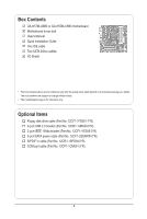
Box Contents GA-H57M-USB3 or GA-H55M-USB3 motherboard Motherboard driver disk User's Manual Quick Installation Guide One IDE cable No. 12CF1-1FD001-7*R) 2-port USB 2.0 bracket (Part No. 12CR1-1UB030-5*R) 2-port IEEE 1394a bracket (Part No. 12CF1-1IE008-0*R) 2-port SATA power cable (Part No. 12CF1- - Gigabyte GA-H55M-USB3 | Manual - Page 7
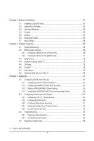
ESATA_1394_USB USB30_LAN NEC D720200F1 LGA1156 PHASE LED IT8720 IDE ATX FDD AUDIO F_AUDIO PCIEX16 RTL8111D SPDIF_O SPDIF_I CODEC PCI1 PCI2 PCIEX4_X1 BAT GA-H57M-USB3/ GA-H55M-USB3 DDR3_2 DDR3_1 DDR3_4 DDR3_3 TSB43AB23 Intel® H57 j Intel® H55 k GIGABYTE SATA2 B_BIOS SATA2_0 M_BIOS - Gigabyte GA-H55M-USB3 | Manual - Page 8
GA-H57M-USB3/GA-H55M-USB3 Motherboard Block Diagram 1 PCI Express x16 CPU CLK+/- (133 MHz) PCIe CLK (100 MHz) LGA1156 CPU DDR3 1666 (O.C.)/1333/1066/800 MHz Dual Channel Memory DMI Interface FDI Interface x16 PCI Express Bus x1 Gen 2 2 USB 3.0 Switch PCI Express Bus x1 Gen 1 NEC D720200F1 - Gigabyte GA-H55M-USB3 | Manual - Page 9
or memory. If you do not have an ESD wrist strap, keep your hands dry and first touch a metal object to eliminate static electricity. • Prior to installing the motherboard, please have it on top of an antistatic pad or within an electrostatic shielding container. • Before unplugging the power supply - Gigabyte GA-H55M-USB3 | Manual - Page 10
in the LGA1156 package (Go to GIGABYTE's website for the latest CPU support list.) L3 cache varies with CPU Intel® H57 Express Chipset j Intel® H55 Express Chipset k 4 x 1.5V DDR3 DIMM sockets supporting up to 16 GB of system memory (Note 1) Dual channel memory architecture Support for DDR3 - Gigabyte GA-H55M-USB3 | Manual - Page 11
w 2 x USB 3.0 ports w 1 x IEEE 1394a port w 1 x eSATA 3Gb/s connector w 1 x RJ-45 port w 6 x audio jacks (Center/Subwoofer Speaker Out/Rear Speaker Out/ Side Speaker Out/Line In/Line Out/Microphone) j Only for GA-H57M-USB3. k Only for GA-H55M-USB3. - 11 - Gigabyte GA-H55M-USB3 | Manual - Page 12
ports, you must install an Intel CPU with integrated graphics. (Note 3) The DVI-D port does not support D-Sub connection by adapter. (Note 4) You can use only one of the onboard digital graphics ports (e.g. DisplayPort, HDMI, and DVI-D) for output when in the BIOS Setup program or when during the - Gigabyte GA-H55M-USB3 | Manual - Page 13
specifications including the CPU, graphics card, memory, hard drive, etc. 1-3-1 Installing the CPU A. Locate the alignment keys on the motherboard CPU socket and the notches on the CPU. LGA1156 CPU Socket Alignment Key Alignment Key Pin One Corner of the CPU Socket LGA1156 CPU Notch Notch - Gigabyte GA-H55M-USB3 | Manual - Page 14
B. Follow the steps below to correctly install the CPU into the motherboard CPU socket. Before installing the CPU, make sure to turn off the computer and unplug the power cord from the power outlet to prevent damage to the CPU. Step 1: Gently press the CPU socket lever handle down and away from the - Gigabyte GA-H55M-USB3 | Manual - Page 15
installation manual for instructions on installing the cooler.) Step 5: After the installation, check the back of the motherboard. If the push pin is inserted as the picture above shows, the installation is complete. Step 6: Finally, attach the power connector of the CPU cooler to the CPU fan - Gigabyte GA-H55M-USB3 | Manual - Page 16
Make sure that the motherboard supports the memory. It is recommended that memory of the same capacity, brand, speed, and chips be used. (Go to GIGABYTE's website for the latest memory support list.) • Always turn off the computer and unplug the power cord from the power outlet before installing the - Gigabyte GA-H55M-USB3 | Manual - Page 17
to install DDR3 DIMMs on this motherboard. Notch DDR3 DIMM A DDR3 memory module has a notch, so it can only fit in one direction. Follow the steps below to correctly install your memory modules in the memory sockets. Step 1: Note the orientation of the memory module. Spread the retaining clips at - Gigabyte GA-H55M-USB3 | Manual - Page 18
computer. If necessary, go to BIOS Setup to make any required BIOS changes for your expansion card(s). 7. Install the driver provided with the expansion card in your operating system. Example: Installing and Removing a PCI Express Graphics Card: • Installing a Graphics Card: Gently push down on the - Gigabyte GA-H55M-USB3 | Manual - Page 19
below for details.) • Please note the HDMI audio output only supports AC3, DTS and 2-channel-LPCM formats. (AC3 and DTS require the use of an external decoder for decoding.) In Windows Vista, select Start>Control Panel>Sound> Playback, set Intel(R) Display Audio HDMI 2 to the default playback device - Gigabyte GA-H55M-USB3 | Manual - Page 20
SATA Hard Drive(s)," for instructions on configuring a RAID array. j Only for GA-H57M-USB3. (Note 1) To use the onboard DisplayPort, HDMI, DVI-D, and D-Sub ports, you must install an Intel CPU with integrated graphics. (Note 2) The DVI-D port does not support D-Sub connection by adapter - Gigabyte GA-H55M-USB3 | Manual - Page 21
LED: State Description Blinking Data transmission or receiving is occurring Off No data transmission or receiving is occurring USB 3.0/2.0 Port The USB 3.0 port supports the USB 3.0 specification and is compatible to the USB and then remove it from the motherboard. • When removing the cable, - Gigabyte GA-H55M-USB3 | Manual - Page 22
20) PHASE_LED j Only for GA-H57M-USB3. Read the following guidelines before power cord from the power outlet to prevent damage to the devices. • After installing the device and before turning on the computer, make sure the device cable has been securely attached to the connector on the motherboard - Gigabyte GA-H55M-USB3 | Manual - Page 23
orientation. The 12V power connector mainly supplies power to the CPU. If the 12V power connector is not connected, the computer will not start. • Use of a power supply providing a 2x4 12V power connector is recommended by the CPU manufacturer when using an Intel Extreme Edition CPU (130W). • To - Gigabyte GA-H55M-USB3 | Manual - Page 24
fan cable, be sure to connect it in the correct orientation (the black connector wire is the ground wire). The motherboard supports CPU fan speed control, which requires the use of a CPU fan with fan speed control design. For optimum heat dissipation, it is recommended that a system fan be installed - Gigabyte GA-H55M-USB3 | Manual - Page 25
even number.) • A RAID 10 configuration requires at least four hard drives and the total number of hard drives must be an even number. Please connect the L-shaped end of the SATA 3Gb/s cable to your SATA hard drive. j Only for GA-H57M-USB3. k Only for GA-H55M-USB3. - 25 - Hardware Installation - Gigabyte GA-H55M-USB3 | Manual - Page 26
supports a single SATA device. The GIGABYTE SATA2 controller supports RAID 0 and RAID 1. Refer to Chapter 5, "Configuring SATA Hard Drive(s)," for instructions on configuring a RAID battery provides power to keep the values (such as BIOS configurations, date, and time information) in the CMOS when - Gigabyte GA-H55M-USB3 | Manual - Page 27
beep will be heard if no problem is detected at system startup. If a problem is detected, the BIOS may issue beeps in different patterns to indicate the problem. Refer to Chapter 5, "Troubleshooting," for information about beep codes. • HD (Hard Drive Activity LED, Blue) Connects to the hard drive - Gigabyte GA-H55M-USB3 | Manual - Page 28
The front panel audio header supports Intel High Definition audio (HD) and AC'97 audio. You may connect your chassis front panel audio module to this header. Make sure the wire assignments of the module connector match the pin assignments of the motherboard header. Incorrect connection between the - Gigabyte GA-H55M-USB3 | Manual - Page 29
Definition 1 Power 1 2 SPDIFI 3 GND 14) SPDIF_O (S/PDIF Out Header) This header supports digital S/PDIF Out and connects a S/PDIF digital audio cable (provided by expansion cards) for digital audio output from your motherboard to certain expansion cards like graphics cards and sound cards. For - Gigabyte GA-H55M-USB3 | Manual - Page 30
the power outlet to prevent damage to the IEEE 1394a bracket. • To connect an IEEE 1394a device, attach one end of the device cable to your computer and then attach the other end of the cable to the IEEE 1394a device. Ensure that the cable is securely connected. j Only for GA-H57M-USB3 - Gigabyte GA-H55M-USB3 | Manual - Page 31
unplug the power cord from the power outlet before clearing the CMOS values. • After clearing the CMOS values and before turning on your computer, be sure to remove the jumper cap from the jumper. Failure to do so may cause damage to the motherboard. • After system restart, go to BIOS Setup to load - Gigabyte GA-H55M-USB3 | Manual - Page 32
20) PHASE LED The number of lighted LEDs indicates the CPU loading. The higher the CPU loading, the more the number of lighted LEDs. To enable the Phase LED display function, please first enable Dynamic Energy Saver™ 2. Refer to Chapter 4, "Dynamic Energy Saver™ 2," for more details. Hardware - Gigabyte GA-H55M-USB3 | Manual - Page 33
the GIGABYTE Q-Flash or @BIOS utility. • Q-Flash allows the user to quickly and easily upgrade or back up BIOS without entering the operating system. • @BIOS is a Windows-based utility that searches and downloads the latest version of BIOS from the Internet and updates the BIOS. For instructions on - Gigabyte GA-H55M-USB3 | Manual - Page 34
.00PG, An Energy Star Ally Copyright (C) 1984-2009, Award Software, Inc. Motherboard Model BIOS Version H55M/H57M-USB3 E8 . . . . : BIOS Setup : XpressRecovery2 : Boot Menu : Qflash 12/22/2009-H55/H57-7A89TG0PC-00 Function Keys Function Keys SATA Mode Message: "SATA is found - Gigabyte GA-H55M-USB3 | Manual - Page 35
Power Management Setup PC Health Status Load Fail-Safe Defaults Load Optimized Defaults Set Supervisor Password Set User Password Save & Exit Setup Exit Without Saving ESC: Quit F8: Q-Flash Select Item F10: Save & Exit Setup Change CPU's Clock & Voltage F11: Save CMOS to BIOS F12: Load CMOS - Gigabyte GA-H55M-USB3 | Manual - Page 36
menu to configure the device boot order, advanced features available on the CPU, and the primary display adapter. Integrated Peripherals Use this menu to configure all peripheral devices, such as IDE, SATA, USB, integrated audio, and integrated LAN, etc. Power Management Setup Use this menu to - Gigabyte GA-H55M-USB3 | Manual - Page 37
Optimized Defaults (Note 1) This item is present only if you install a CPU that supports this feature. For more information about Intel CPUs' unique features, please visit Intel's website. (Note 2) This item appears only if you install a memory module that supports this feature. - 37 - BIOS Setup - Gigabyte GA-H55M-USB3 | Manual - Page 38
state to decrease power consumption. Auto lets the BIOS automatically configure this setting. (Default: Auto) (Note) This item is present only if you install a CPU that supports this feature. For more information about Intel CPUs' unique features, please visit Intel's website. BIOS Setup - 38 - Gigabyte GA-H55M-USB3 | Manual - Page 39
. Note: If your system fails to boot after overclocking, please wait for 20 seconds to allow for automated system reboot, or clear the CMOS values to reset the board to default values. (Default: Disabled) BCLK Frequency(Mhz) Allows you to manually set the CPU base clock. The adjustable range is from - Gigabyte GA-H55M-USB3 | Manual - Page 40
set the CPU clock prior to the Chipset clock. Options are: 0ps~750ps. (Default: 0ps) IOH Clock Skew Allows you to set the Chipset clock prior to the CPU clock. Options are: 0ps~750ps. (Default: 0ps) (Note) This item appears only if you install a memory module that supports this feature. BIOS Setup - Gigabyte GA-H55M-USB3 | Manual - Page 41
is set to Profile1 or Profile2, this item will display the value based on the SPD data on the XMP memory. Profile QPI Voltage The value displayed here is dependent on the CPU being used. (Note) This item appears only if you install a memory module that supports this feature. - 41 - BIOS Setup - Gigabyte GA-H55M-USB3 | Manual - Page 42
>>>>> Channel A/B Timing Settings CMOS Setup Utility-Copyright (C) 1984-2009 Award Software Channel A Timing Settings >>>>> Channel A Standard Timing Control x CAS Latency Time 9 x tRFC Options are: Auto (default), 1~255. ESC: Exit F1: General Help F7: Optimized Defaults BIOS Setup - 42 - - Gigabyte GA-H55M-USB3 | Manual - Page 43
may result in damage to your CPU or reduce the useful life of the CPU. CPU Vcore The default is Auto. Dynamic Vcore(DVID) This option is configurable only when CPU Vcore is set to Normal. The default is Auto. QPI/Vtt Voltage The default is Auto. Graphics Core The default is Auto. - 43 - BIOS Setup - Gigabyte GA-H55M-USB3 | Manual - Page 44
Isochronous Support Determines whether to enable specific streams within the CPU and Chipset. (Default: Enabled) (Note) This item is present only if you install a CPU that supports this feature. For more information about Intel CPUs' unique features, please visit Intel's website. BIOS Setup - Gigabyte GA-H55M-USB3 | Manual - Page 45
, memory frequency, total memory size , CPU temperature, Chipset temperature, Vcore, and memory voltage. (Note) This item is present only if you install a CPU that supports this feature. For more information about Intel CPUs' unique features, please visit Intel's website. - 45 - BIOS Setup - Gigabyte GA-H55M-USB3 | Manual - Page 46
Help F7: Optimized Defaults CMOS Setup Utility-Copyright (C) 1984-2009 Award Software Standard CMOS Features Extended Memory Total Memory 827M 832M Item Help methods below: • Auto Lets the BIOS automatically detect IDE/SATA devices during the POST. (Default) BIOS Setup - 46 - - Gigabyte GA-H55M-USB3 | Manual - Page 47
only and are determined by the BIOS POST. Base Memory Also called conventional memory. Typically, 640 KB will be reserved for the MS-DOS operating system. Extended Memory The amount of extended memory. Total Memory The total amount of memory installed on the system. - 47 - BIOS Setup - Gigabyte GA-H55M-USB3 | Manual - Page 48
BIOS Features CMOS Setup Utility-Copyright (C) 1984-2009 Award Software Advanced BIOS Features } Hard Disk Boot Priority Quick Boot First Boot Device Second Boot Device Third Boot Device Password Check HDD S.M.A.R.T. Capability Limit CPUID Max. to 3 (Note) No-Execute Memory - Gigabyte GA-H55M-USB3 | Manual - Page 49
use only this memory for display. Options are: 32MB+2MB for GTT, 64MB+2MB for GTT (default), 128MB+2MB for GTT. (Note) This item is present only if you install a CPU that supports this feature. For more information about Intel CPUs' unique features, please visit Intel's website. - 49 - BIOS Setup - Gigabyte GA-H55M-USB3 | Manual - Page 50
to install operating systems that do not support Native mode. Enabled Allows the SATA controllers to operate in Native IDE mode. (Default) Enable Native IDE mode if you wish to install operating systems that support Native mode. j Only for GA-H57M-USB3. BIOS Setup - 50 - - Gigabyte GA-H55M-USB3 | Manual - Page 51
USB storage devices, including USB flash drives and USB hard drives during the POST. (Default: Enabled) Azalia Codec Enables or disables the onboard audio function. (Default: Auto) If you wish to install a 3rd party add-in audio card in network card instead of CMOS Setup motherboard the motherboard, the - Gigabyte GA-H55M-USB3 | Manual - Page 52
to decide whether to activate the boot ROM integrated with the onboard LAN chip. (Default: Disabled) Onboard USB 3.0 Controller (NEC USB 3.0 Controller) Enables or disables the NEC USB 3.0 controller. (Default: Enabled) Onboard SATA/IDE Device (GIGABYTE SATA2, IDE and GSATA2_5/6 Connectors) Enables - Gigabyte GA-H55M-USB3 | Manual - Page 53
providing at least 1A on the +5VSB lead. (Default: Enabled) Power On by Ring Allows the system to be awakened from an ACPI sleep state by a wake-up signal from a modem that supports wake-up function. (Default: Enabled) (Note) Supported on Windows 7/Vista operating system only. - 53 - BIOS Setup - Gigabyte GA-H55M-USB3 | Manual - Page 54
than 1W power in S5 (shutdown) state. (Default: Disabled) Note: When this item is set to Enabled, the following four functions will become unavailable: PME event wake up, power on by mouse, power on by keyboard, and wake on LAN. (Note) Supported on Windows 7/Vista operating system only. BIOS Setup - Gigabyte GA-H55M-USB3 | Manual - Page 55
detection device attached to the motherboard CI header. If the system chassis cover is removed, this field will show "Yes", otherwise it will show "No". To clear the chassis intrusion status record, set Reset Case Open Status to Enabled, save the settings to the CMOS, and then restart your system - Gigabyte GA-H55M-USB3 | Manual - Page 56
a 3-pin CPU fan. PWM Sets PWM mode for a 4-pin CPU fan. Note: The Voltage mode can be set for a 3-pin CPU fan or a 4-pin CPU fan. However, for a 4-pin CPU fan that is not designed following Intel PWM fan specifications, selecting PWM mode may not effectively reduce the fan speed. BIOS Setup - 56 - Gigabyte GA-H55M-USB3 | Manual - Page 57
CMOS from BIOS Press on this item and then press the key to load the optimal BIOS default settings. The BIOS defaults settings help the system to operate in optimum state. Always load the Optimized defaults after updating the BIOS or after clearing the CMOS values. - 57 - BIOS Setup - Gigabyte GA-H55M-USB3 | Manual - Page 58
2-11 Set Supervisor/User Password CMOS Setup Utility-Copyright (C) 1984-2009 Award Software MB Intelligent Tweaker(M.I.T.) Standard CMOS Features Advanced BIOS Features Integrated Peripherals Power Management SetupEnter Password: PC Health Status Load Fail-Safe Defaults Load Optimized - Gigabyte GA-H55M-USB3 | Manual - Page 59
Password Integrated Peripherals Set User Password Power Management Setup Save & Exit Setup PC Health Status Exit Without Saving ESC: Quit F8: Q-Flash Select Item F10: Save & Exit Setup Save Data to CMOS F11: Save CMOS to BIOS F12: Load CMOS from BIOS Press on this item and - Gigabyte GA-H55M-USB3 | Manual - Page 60
BIOS Setup - 60 - - Gigabyte GA-H55M-USB3 | Manual - Page 61
to restart your system. You can install other applications included in the motherboard driver disk. • For USB 2.0 driver support under the Windows XP operating system, please install the Windows XP Service Pack 1 or later. After installing the SP1 (or later), if a question mark still exists - Gigabyte GA-H55M-USB3 | Manual - Page 62
applications that GIGABYTE develops and some free software. You can click the Install button on the right of an item to install it. 3-3 Technical Manuals This page provides GIGABYTE's application guides, content descriptions for this driver disk, and the motherboard manuals. Drivers Installation - Gigabyte GA-H55M-USB3 | Manual - Page 63
3-4 Contact For the detailed contact information of the GIGABYTE Taiwan headquarter or worldwide branch offices, click the URL on this page to link to the GIGABYTE website. 3-5 System This page provides the basic system information. - 63 - Drivers Installation - Gigabyte GA-H55M-USB3 | Manual - Page 64
Center To update the BIOS, drivers, or applications, click the Download Center button to link to the GIGABYTE website. The latest version of the BIOS, drivers, or applications will be displayed. 3-7 New Utilities This page provides a quick link to GIGABYTE's lately developed utilities for users - Gigabyte GA-H55M-USB3 | Manual - Page 65
system memory • VESA compatible graphics card • Windows XP with SP1 or later, Windows Vista • Xpress Recovery and Xpress Recovery2 are different utilities. For example, a backup file created with Xpress Recovery cannot be restored using Xpress Recovery2. • USB hard drives are not supported. • Hard - Gigabyte GA-H55M-USB3 | Manual - Page 66
the top). Please note that if there is no enough unallocated space, Xpress Recovery2 cannot save the backup file. B. Accessing Xpress Recovery2 1. Boot from the motherboard driver disk to access Xpress Recovery2 for the first time. When you see the following message: Press any key to startup Xpress - Gigabyte GA-H55M-USB3 | Manual - Page 67
D. Using the Restore Function in Xpress Recovery2 Select RESTORE to restore the backup to your hard drive in case the system breaks down. The RESTORE option will not be present if no backup is created before. E. Removing the Backup Step 1: If you wish to remove the backup file, select REMOVE. Step - Gigabyte GA-H55M-USB3 | Manual - Page 68
Q-Flash Utility A. Before You Begin 1. From GIGABYTE's website, download the latest compressed BIOS update file that matches your motherboard model. 2. Extract the file and save the new BIOS file (e.g. h57musb3.f1) to your USB flash drive, or hard drive. Note: The USB flash drive or hard drive must - Gigabyte GA-H55M-USB3 | Manual - Page 69
hi:Move Total size : 0 ESC:Reset Free size : 0 F10:Power Off 3. Select the BIOS update file and press . Make sure the BIOS update file matches your motherboard model. Step 2: The process of the system reading the BIOS file from the USB flash drive is displayed on the screen. When the - Gigabyte GA-H55M-USB3 | Manual - Page 70
the POST, press to enter BIOS Setup. Select Load Optimized Defaults and press to load BIOS defaults. System will re-detect all peripheral devices after a BIOS update, so we recommend that you reload BIOS defaults. CMOS Setup Utility-Copyright (C) 1984-2009 Award Software MB - Gigabyte GA-H55M-USB3 | Manual - Page 71
. If the BIOS update file for your motherboard is not present on the @BIOS server site, please manually download the BIOS update file from GIGABYTE's website and follow the instructions in "Update the BIOS without Using the Internet Update Function" below. 2. Update the BIOS without Using the - Gigabyte GA-H55M-USB3 | Manual - Page 72
in EasyTune 6 may differ by motherboard model. Grayed-out area(s) indicates that the item is not configurable or the function is not supported. Incorrectly doing overclock/overvoltage may result in damage to the hardware components such as CPU, chipset, and memory and reduce the useful life of - Gigabyte GA-H55M-USB3 | Manual - Page 73
in taskbar) 14 INFO/Help 15 Motherboard Phase LED On/Off Switch (Default: On) 16 Live Utility Update (Check for the latest utility version) • The above data is for reference only. Actual performance may vary depending on motherboard model. • CPU Power and Power Scores are for reference only - Gigabyte GA-H55M-USB3 | Manual - Page 74
to run in taskbar) 13 INFO/Help 14 Motherboard Phase LED On/Off Switch (Default: On) 15 Live Utility Update (Check for the latest utility version) C. Stealth Mode In Stealth Mode, the system continues to work with the user-defined power saving settings, even after the system is restarted - Gigabyte GA-H55M-USB3 | Manual - Page 75
for using Q-Share After installing Q-Share from the motherboard driver disk, go to Start>All Programs>GIGABYTE>Q-Share. exe to launch the Q-Share tool. shared data folder Changes the data folder to be shared (Note) Updates Q-Share online Displays the current Q-Share version Exits Q-Share ( - Gigabyte GA-H55M-USB3 | Manual - Page 76
, delivering greater efficiency for daily use. Instructions: Select the Enable check box below the BIOS QuickBoot or OS QuickBoot item and then click Save to save the settings. SMART QuickBoost SMART QuickBoost features quick and effortless CPU overclocking for novice and experienced users alike - Gigabyte GA-H55M-USB3 | Manual - Page 77
(partitioned on NTFS file system) in Windows Vista. Instructions: In the main menu, click the copy and click the Copy button. The files/folders listed on the screen are read-only so you cannot BIOS simultaneously, which can prevent loss of the data in case the system/hard drive fails. Instructions - Gigabyte GA-H55M-USB3 | Manual - Page 78
drive or copied to an external storage device (Note 5). Instructions: Select the Enable check box at the bottom of time, the backup will be performed on the next boot. We recommend that you preserve at least 25 percent BIOS Setup program to prevent the system time being changed by other users. - Gigabyte GA-H55M-USB3 | Manual - Page 79
main menu and click Save to save the settings. Button Standby Suspend Disable Description Enters Power on Suspend mode Enters Suspend to RAM mode Disables this function The Bluetooth dongle included in the motherboard package(Note 2) allows you to wake up the system from Suspend to RAM mode - Gigabyte GA-H55M-USB3 | Manual - Page 80
1: Configure the system BIOS Enter the system BIOS Setup program, set eXtreme Hard Drive (X.H.D) under the Integrated Peripherals menu to Enabled to enable RAID for the Intel SATA controllers. Step 2: Install the RAID driver and operating system The X.H.D utility supports Windows 7/Vista/XP. Before - Gigabyte GA-H55M-USB3 | Manual - Page 81
. (For example, on this motherboard, the SATA2_0, SATA2_1, SATA2_2, SATA2_3, and SATA2_4 ports are supported by H57 Chipset.) Then connect the power connector from your power supply to the hard drive. j Only for GA-H57M-USB3. (Note 1) Skip this step if you do not want to create RAID array. (Note - Gigabyte GA-H55M-USB3 | Manual - Page 82
press to enter BIOS Setup during the POST (Power-On Self-Test). To create RAID, set PCH SATA Control Mode under the Integrated Peripherals menu to RAID(XHD) (Figure 1) (IDE by default). If you do not want to create RAID, set this item to IDE or AHCI. CMOS Setup Utility-Copyright (C) 1984 - Gigabyte GA-H55M-USB3 | Manual - Page 83
C. Configuring a RAID array in RAID BIOS Enter the RAID BIOS setup utility to configure a RAID array. Skip this step and proceed with the installation of Windows operating system for a non-RAID configuration. Step 1: After the POST memory test begins and before the operating system boot begins, - Gigabyte GA-H55M-USB3 | Manual - Page 84
Figure 4). RAID levels supported include RAID 0, RAID 1, Recovery, RAID 10, and RAID 5 (the selections available depend on the number of the hard drives being installed). Press to proceed. Intel(R) Rapid Storage Technology - option ROM - 9.5.0.1037 Copyright(C) 2003-09 Intel Corporation. All - Gigabyte GA-H55M-USB3 | Manual - Page 85
(0) Member Disk(0) [hi]-Select [ESC]-Exit Figure 7 [ENTER]-Select Menu To exit the RAID BIOS utility, press or select 5. Exit in MAIN MENU. Now, you can proceed to create the SATA RAID/AHCI driver diskette and install the SATA RAID/AHCI driver and operating system. - 85 - Appendix - Gigabyte GA-H55M-USB3 | Manual - Page 86
Storage Technology - option ROM - 9.5.0.1037 Copyright(C) 2003-09 Intel Corporation. All Rights Reserved. [ MAIN MENU ] 1. Create RAID Volume 2. Delete RAID Volume 5. Exit 3. Reset Disks to Non-RAID 4. Recovery Volume Options RAID Volumes : None defined. [ DISK/VOLUME INFORMATION ] Physical - Gigabyte GA-H55M-USB3 | Manual - Page 87
Status Non-RAID Disk Non-RAID Disk Choose the RAID level: update data from the master drive to the recovery drive manually using the Update Volume function of the Intel sync option: On Request: volume is updated manually Continuous: volume is updated automatically [hi]-Change [TAB]-Next [ESC - Gigabyte GA-H55M-USB3 | Manual - Page 88
RAID array, select Delete RAID Volume in MAIN MENU and press . In the DELETE VOLUME MENU section, use the up or down arrow key to select the array to be deleted and press . When prompted to confirm your selection (Figure 12), press to confirm or to abort. Intel non-RAID. - Gigabyte GA-H55M-USB3 | Manual - Page 89
available SATA port on the motherboard. On this motherboard, the GSATA2_0 and GSATA2_1 ports are supported by the GIGABYTE SATA2 SATA controller. Then connect the power connector from your power supply to the hard drive. B. Configuring SATA controller mode in BIOS Setup Make sure to configure the - Gigabyte GA-H55M-USB3 | Manual - Page 90
of Windows operating system for a non-RAID configuration. After the POST memory test begins and before the operating system boot begins, look for a message which says "Press to enter RAID Setup Utility" (Figure 2). Press + to enter the RAID setup utility. GIGABYTE Technology - Gigabyte GA-H55M-USB3 | Manual - Page 91
GB Gigabyte Technology Corp. RAID Setup Utility v1.07.06 [ Hard Disk Drive List ] Model Name HDD0: ST3120026AS HDD1: ST3120026AS Available 120 GB 120 GB Type/Status Non-RAID Non-RAID Confirm Creation [ RAID Disk Drive List ] [ Help ] Select RAID Level RAID 0 RAID 1 JBOD - Gigabyte GA-H55M-USB3 | Manual - Page 92
a RAID mode is selected, RAID BIOS automatically assigns the two hard drives installed as the RAID drives. 4. Set Block Size (RAID 0 only RAID ] Name: Level: Disks: Block: Size: GRAID 0-Stripe Select Disk 128 KB 240 GB Gigabyte Technology Corp. RAID Setup Utility v1.07.06 [ Hard Disk Drive List - Gigabyte GA-H55M-USB3 | Manual - Page 93
bar to the RAID Disk Drive List block. Select the array and press . A small window displaying the array information will appear in the center of the screen (Figure 9). Gigabyte Technology Corp. RAID Setup Utility v1.07.06 [ Main Menu ] Create RAID Disk Drive Delete RAID Disk Drive Revert - Gigabyte GA-H55M-USB3 | Manual - Page 94
the RAID BIOS utility, then press (Figure 10). [ Main Menu ] Create RAID Disk Drive Delete RAID Disk Drive Revert HDD to Non-RAID Solve Mirror Conflict Rebuild Mirror Drive Save And Exit Setup Exit Without Saving Gigabyte Technology Corp. RAID Setup Utility v1.07.06 [ Hard Disk Drive List - Gigabyte GA-H55M-USB3 | Manual - Page 95
copy the SATA controller driver from the motherboard driver disk to a USB flash drive. See the instructions below about how to copy the driver in MS-DOS and Windows mode. In MS-DOS mode: Prepare a startup disk that has CD-ROM support and a blank formatted floppy disk. Steps: 1: Boot from the startup - Gigabyte GA-H55M-USB3 | Manual - Page 96
RAID/AHCI driver and press . Then a controller menu similar to Figure 2 below will appear. Select Intel(R) ICH8R/ICH9R/ICH10R/DO/5 Series/3400 Series SATA RAID Controller and press . Windows Setup You have chosen to configure a SCSI Adapter for use with Windows, using a device support - Gigabyte GA-H55M-USB3 | Manual - Page 97
>. Windows Setup You have chosen to configure a SCSI Adapter for use with Windows, using a device support disk provided by an adapter manufacturer. Select the SCSI Adapter you want from the following list, or press ESC to return to the previous screen. RAID/AHCI Driver for GIGABYTE GBB36X - Gigabyte GA-H55M-USB3 | Manual - Page 98
the Intel H57: Step 1: Restart your system to boot from the Windows Vista setup disk and perform standard OS installation steps. When a screen similar to that below appears, select Load Driver (Figure 4). Figure 4 Step 2: Insert the motherboard driver disk (Method A) or the floppy disk/USB flash - Gigabyte GA-H55M-USB3 | Manual - Page 99
Step 3: When a screen as shown in Figure 6 appears, select Intel(R) ICH8R/ICH9R/ICH10R/DO/5 Series/3400 Series SATA RAID Controller and click Next. Figure 6 Step 4: After the driver is loaded, select the RAID/AHCI drive(s) where you want to install the operating system and then click Next to - Gigabyte GA-H55M-USB3 | Manual - Page 100
the Windows Vista setup disk and perform standard OS installation steps. When a screen similar to that below appears (RAID/AHCI hard drive(s) will not be detected at this stage), select Load Driver (Figure 8). Figure 8 Step 2: Insert the motherboard driver disk (Method A) or the floppy disk/USB - Gigabyte GA-H55M-USB3 | Manual - Page 101
Step 3: When a screen as shown in Figure 10 appears, select GIGABYTE GBB36X Controller and click Next. Figure 10 Step 4: After the driver is loaded, select the RAID/AHCI drive(s) where you want to install the operating system and then click Next to continue the OS installation (Figure 11). Figure - Gigabyte GA-H55M-USB3 | Manual - Page 102
screen appears, indicating that an automatic rebuild will be performed after you enter the operating system (look for the Intel Storage Console icon in the notification area, which will show that a RAID volume is being rebuilt). If you do not enable automatic rebuild on this stage, you have to - Gigabyte GA-H55M-USB3 | Manual - Page 103
has been installed from the motherboard driver disk. Then launch the Intel Rapid Stroage Technology utility from All Programs in the Start menu. Step 1: Go to the Manage menu and click Rebuild to another disk in Manage Volume. Step 2: Select a new drive to rebuild the RAID and click Rebuild. The - Gigabyte GA-H55M-USB3 | Manual - Page 104
Recovery Volume only) When two hard drives are set to Recovery Volume in Update on Request mode, you can restore the master drive data to the last instructions to complete and exit the RAID Configuration Utility. Intel(R) Rapid Storage Technology - option ROM - 9.5.0.1037 Copyright(C) 2003-09 Intel - Gigabyte GA-H55M-USB3 | Manual - Page 105
Mirror Drive Save And Exit Setup Exit Without Saving Gigabyte Technology Corp. RAID Setup Utility v1.07.06 [ Hard Disk Drive List ] Model Name HDD0: ST3120026AS HDD1: ST3120026AS Capacity 120 GB 120 GB Type/Status RAID Inside Non-RAID [ RAID Disk Drive List ] Model Name RDD0: GRAID - Gigabyte GA-H55M-USB3 | Manual - Page 106
has been installed from the motherboard driver disk. Launch the GIGABYTE RAID CONFIGURER from All Programs in the Start menu. Step 1: In the GIGABYTE RAID CONFIGURER screen, right-click on the array to be rebuilt in the RAID LIST block. Select Rebuild Raid. (Or click the Rebuild icon in the tool - Gigabyte GA-H55M-USB3 | Manual - Page 107
2/4/5.1/7.1-Channel Audio The motherboard provides six audio jacks on the back panel which support 2/4/5.1/7.1-channel (Note) Configuring Speakers (The following instructions use Windows Vista as the example operating system.) Step 1: After installing the audio driver, the HD Audio Manager icon - Gigabyte GA-H55M-USB3 | Manual - Page 108
Speakers screen, click the Speaker Configuration tab. In the Speaker Configuration list, select Stereo, Quadraphonic, 5.1 Speaker, or 7.1 Speaker according to of speaker configuration you wish to set up. Then the speaker setup is completed. B. Configuring Sound Effect You may configure an audio - Gigabyte GA-H55M-USB3 | Manual - Page 109
S/PDIF In 1. Installing the S/PDIF In Cable: Step 1: First, attach the connector at the end of the cable to the SPDIF_I header on your motherboard. Step 2: Secure the metal bracket to the chassis back panel with a screw. 2. Configuring S/PDIF In: On the Digital Input screen, click the Default - Gigabyte GA-H55M-USB3 | Manual - Page 110
to complete. (Note) If you have connected a S/PDIF digital audio cable (provided by expansion cards) to the 2-pin S/PDIF Out header (SPDIF_O) on the motherboard to output digital audio to your expansion card, you can enter the Digital Output(Optical) screen to configure further settings, such as - Gigabyte GA-H55M-USB3 | Manual - Page 111
5-2-3 Configuring Microphone Recording Step 1: After installing the audio driver, the HD Audio Manager icon will appear in the notification area. Double-click the icon to access the HD Audio Manager. Step 2: Connect your microphone - Gigabyte GA-H55M-USB3 | Manual - Page 112
be transformed into multi-channel audio, creating a virtual surround sound environment . (Note) Install the Dolby GUI Software driver from the motherboard driver disk. Click the Start icon Programs, Dolby Control Center to access the utility. (The following illustration demonstrates a 7.1-speaker - Gigabyte GA-H55M-USB3 | Manual - Page 113
Step 4: To raise the recording and playback volume for the microphone, click the Microphone Boost icon on the right of the Recording Volume slider and set the Microphone Boost level. Step 5: After completing the settings above, click Start, point to All Programs, point to Accessories, and then click - Gigabyte GA-H55M-USB3 | Manual - Page 114
. Be sure to save the recorded audio file upon completion. B. Playing the Recorded Sound You can play your recording in a digital media player program that supports your audio file format. Appendix - 114 - - Gigabyte GA-H55M-USB3 | Manual - Page 115
you identify possible computer problems. (For reference only.) 1 short: System boots successfully 1 long, 3 short: Keyboard error 2 short: CMOS setting error 1 long, 9 short: BIOS ROM error 1 long, 1 short: Memory or motherboard error Continuous long beeps: Graphics card not inserted properly - Gigabyte GA-H55M-USB3 | Manual - Page 116
Connect the CPU cooler power cable to the motherboard. Yes The problem is verified and solved. Check if the memory is installed properly on the memory slot. No Correctly insert the memory into the memory socket. Yes The problem is verified and solved. Insert the graphics card. Connect the - Gigabyte GA-H55M-USB3 | Manual - Page 117
on, is the CPU cooler running? No The power supply, CPU or CPU socket might fail. Yes Check if there is display on your monitor. Yes Turn off the computer. Plug in the keyboard and mouse and restart the computer. The problem is verified and solved. No The graphics card, expansion slot, or - Gigabyte GA-H55M-USB3 | Manual - Page 118
GIGABYTE. Our Commitment to Preserving the Environment In addition to high-efficiency performance, all GIGABYTE motherboards office, your household waste disposal service or where you purchased the Customer Care number listed in your product's user's manual and we will be glad to help you - Gigabyte GA-H55M-USB3 | Manual - Page 119
that potentially hazardous substances are not released into the environment and are disposed of properly. China Restriction of Hazardous Substances Table The following table is supplied in compliance with China's Restriction of Hazardous Substances (China RoHS) requirements: - 119 - Appendix - Gigabyte GA-H55M-USB3 | Manual - Page 120
Appendix - 120 - - Gigabyte GA-H55M-USB3 | Manual - Page 121
- 121 - Appendix - Gigabyte GA-H55M-USB3 | Manual - Page 122
Appendix - 122 - - Gigabyte GA-H55M-USB3 | Manual - Page 123
- 123 - Appendix - Gigabyte GA-H55M-USB3 | Manual - Page 124
Appendix - 124 - - Gigabyte GA-H55M-USB3 | Manual - Page 125
- 125 - Appendix - Gigabyte GA-H55M-USB3 | Manual - Page 126
Appendix - 126 - - Gigabyte GA-H55M-USB3 | Manual - Page 127
231, Taiwan TEL: +886-2-8912-4000 FAX: +886-2-8912-4003 Tech. and Non-Tech. Support (Sales/Marketing) : http://ggts.gigabyte.com.tw WEB address (English): http://www.gigabyte.com.tw WEB address (Chinese): http://www.gigabyte.tw • G.B.T. INC. - U.S.A. TEL: +1-626-854-9338 FAX: +1-626-854-9339 Tech - Gigabyte GA-H55M-USB3 | Manual - Page 128
.rs • Kazakhstan WEB address : http://www.gigabyte.kz You may go to the GIGABYTE website, select your language in the language list on the top right corner of the website. • GIGABYTE Global Service System To submit a technical or non-technical (Sales/Marketing) question, please link to: http://ggts
-
 1
1 -
 2
2 -
 3
3 -
 4
4 -
 5
5 -
 6
6 -
 7
7 -
8
-
9
-
10
-
11
-
12
-
13
-
14
-
15
-
16
-
17
-
18
-
19
-
20
-
21
-
22
-
23
-
24
-
25
-
26
-
27
-
28
-
29
-
30
-
31
-
32
-
33
-
34
-
35
-
36
-
37
-
38
-
39
-
40
-
41
-
42
-
43
-
44
-
45
-
46
-
47
-
48
-
49
-
50
-
51
-
52
-
53
-
54
-
55
-
56
-
57
-
58
-
59
-
60
-
61
-
62
-
63
-
64
-
65
-
66
-
67
-
68
-
69
-
70
-
71
-
72
-
73
-
74
-
75
-
76
-
77
-
78
-
79
-
80
-
81
-
82
-
83
-
84
-
85
-
86
-
87
-
88
-
89
-
90
-
91
-
92
-
93
-
94
-
95
-
96
-
97
-
98
-
99
-
100
-
101
-
102
-
103
-
104
-
105
-
106
-
107
-
108
-
109
-
110
-
111
-
112
-
113
-
114
-
115
-
116
-
117
-
118
-
119
-
120
-
121
-
122
-
123
-
124
-
125
-
126
-
127
-
128
 |
 |

GA-H57M-USB3
GA-H55M-USB3
LGA1156 socket motherboard for Intel
®
Core
™
i7 processor family/
Intel
®
Core
™
i5 processor family/ Intel
®
Core
™
i3 processor family
User's Manual
Rev. 1001
12ME-H57MUB3-1001R