Gigabyte GA-K8NF9 Ultra User Manual
Gigabyte GA-K8NF9 Ultra Manual
 |
View all Gigabyte GA-K8NF9 Ultra manuals
Add to My Manuals
Save this manual to your list of manuals |
Gigabyte GA-K8NF9 Ultra manual content summary:
- Gigabyte GA-K8NF9 Ultra | User Manual - Page 1
GA-K8NF9 Ultra AMD Socket 939 Processor Motherboard User's Manual Rev. 1001 12ME-K8NF9U-1001R * The WEEE marking on the product indicates this product must not be disposed of with user's other household waste and - Gigabyte GA-K8NF9 Ultra | User Manual - Page 2
Motherboard GA-K8NF9 Ultra Sep. 30, 2005 Motherboard GA-K8NF9 Ultra Sep. 30, 2005 - Gigabyte GA-K8NF9 Ultra | User Manual - Page 3
. „ For detailed product information and specifications, please carefully read the "Product User Manual". „ For detailed information related to Gigabyte's unique features, please go to the "Technology Guide" section on Gigabyte's website to read or download the information you need. For more product - Gigabyte GA-K8NF9 Ultra | User Manual - Page 4
Table of Contents GA-K8NF9 Ultra Motherboard Layout 6 Block Diagram ...7 Chapter 1 Hardware Installation 9 1-1 Considerations Prior to Installation 9 1-2 Feature Summary 10 1-3 Installation of the CPU and Fan Heat Sink 12 1-3-1 Installation of - Gigabyte GA-K8NF9 Ultra | User Manual - Page 5
Installation 49 3-1 Install Chipset Drivers 49 3-2 SoftwareApplication 50 3-3 Software Information 50 3-4 Hardware Information 51 3-5 Contact Us ...51 Serial ATA BIOS Setting Utility Introduction 68 4-1-5 2- / 4- / 6- / 8- Channel Audio Function Introduction 74 4-2 Troubleshooting 78 - 5 - - Gigabyte GA-K8NF9 Ultra | User Manual - Page 6
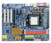
GA-K8NF9 Ultra DDR1 DDR2 DDR3 DDR4 PWR_FAN GA-K8NF9 Ultra Motherboard Layout KB_MS SPDIF_I ATX_12V ATX SPDIF_O PCI1 CD_IN PCI2 PCI3 IR_CIR IDE1 FDD BATTERY CLR_CMOS nVIDIA® nForce4 Ultra S_ATA1_SB S_ATA0_SB S_ATA3_SB S_ATA2_SB SNO82AA2 SNO81BA3 F1_1394 F2_1394 F_PANEL PWR_LED F_USB3 - Gigabyte GA-K8NF9 Ultra | User Manual - Page 7
Memory Hyper Transport Bus 2 PCI Express x 1 Ports PCI-ECLK (100MHz) LAN RJ45 VITESSE 8201 PCI Express x 1 Bus PCI Bus SNO82AA2 SNO81BA3 nVIDIA® nForce4 Ultra BIOS 4 SATA 3Gb/s ATA33/66/100/133 IDE Channels LPC BUS IT8712 IR_CIR Floppy LPT Port COM Port CODEC PS/2 KB/Mouse 24MHz 33MHz - Gigabyte GA-K8NF9 Ultra | User Manual - Page 8
- 8 - - Gigabyte GA-K8NF9 Ultra | User Manual - Page 9
installation, please follow the instructions below: 1. Please turn off the information in the provided manual. 3. Before using the product about any installation steps or have a problem related to the use of the product, the conditions recommended in the user manual. 3. Damage due to improper - Gigabyte GA-K8NF9 Ultra | User Manual - Page 10
/Subwoofer Speaker Out ; Side Speaker Out connection Š SPDIF In/Out connection Š CD In connection Š Supported on the Win 2000/XP operating systems (Note 1) Due to standard PC architecture, a certain amount instead be shown as 3.xxGB memory during system startup. GA-K8NF9 Ultra Motherboard - 10 - - Gigabyte GA-K8NF9 Ultra | User Manual - Page 11
detection CPU / System / Power fan speed detection CPU warning temperature CPU fan failure warning CPU smart fan control Onboard nForce4 Ultra chipset (S_ATA0_SB, S_ATA1_SB, S_ATA2_SB, S_ATA3_SB) - supports data striping (RAID 0) or mirroring (RAID 1) or striping + mirroring (RAID 0+1) function - Gigabyte GA-K8NF9 Ultra | User Manual - Page 12
Before installing the CPU, please comply with the following conditions: 1. Please make sure that the motherboard supports the CPU. 2. Please take note of the one indented corner of the CPU. If you install applying force, please change the positioning of the CPU. GA-K8NF9 Ultra Motherboard - 12 - - Gigabyte GA-K8NF9 Ultra | User Manual - Page 13
layer of heat sink paste on the surface of the CPU. Install all the heat sink components (Please refer to the heat sink manual for detailed installation instructions). Fig.2 Please connect the heat sink power connector to the CPU_FAN connector located on the motherboard so that the heat sink can - Gigabyte GA-K8NF9 Ultra | User Manual - Page 14
If you are unable to insert the module, please switch the direction. The motherboard supports DDR memory modules, whereby BIOS will automatically detect memory capacity and specifications. Memory modules are steps when you wish to remove the DIMM module. GA-K8NF9 Ultra Motherboard - 14 - - Gigabyte GA-K8NF9 Ultra | User Manual - Page 15
English Dual Channel Memory Configuration The GA-K8NF9 Ultra supports the Dual Channel Technology. When the Dual Channel Technology is activated, the bandwidth of memory bus will be double the original one. Due to CPU - Gigabyte GA-K8NF9 Ultra | User Manual - Page 16
outlined below: 1. Read the related expansion card's instruction document before install the expansion card into the computer setup BIOS utility of expansion card from BIOS. 8. Install related driver from the operating system. Installing a PCI Express x 16 expansion GA-K8NF9 Ultra Motherboard - 16 - - Gigabyte GA-K8NF9 Ultra | User Manual - Page 17
, scanner, zip, speaker...etc. have a standard USB interface. Also make sure your OS supports USB controller. If your OS does not support USB controller, please contact OS vendor for possible patch or driver upgrade. For more information please contact your OS or device(s) vendors. Line In Devices - Gigabyte GA-K8NF9 Ultra | User Manual - Page 18
9) PWR_LED 6 10 17 8 9 11 4 15 14 10) BATTERY 11) F_PANEL 12) F_AUDIO 13) CD_IN 14) F_USB1 / F_USB2 / F_USB3 15) F1_1394 / F2_1394 16) IR_CIR 17) CLR_CMOS GA-K8NF9 Ultra Motherboard - 18 - - Gigabyte GA-K8NF9 Ultra | User Manual - Page 19
English 1/2) ATX_12V/ATX (Power Connector) With the use of the power connector, the power supply can supply enough stable power to all the components on the motherboard. Before connecting the power connector, please make sure that all components and devices are properly installed. Align the power - Gigabyte GA-K8NF9 Ultra | User Manual - Page 20
connector is used to connect the FDD cable while the other end of the cable connects to the FDD drive. The types of FDD drives supported are: 360KB, 720KB, 1.2MB, 1.44MB and 2.88MB. Please connect the red power connector wire to the pin1 position. 34 33 GA-K8NF9 Ultra Motherboard 2 1 - 20 - - Gigabyte GA-K8NF9 Ultra | User Manual - Page 21
as Master and the other as Slave (for information on settings, please refer to the instructions located on the IDE device). 40 39 2 IDE2 1 IDE1 8) S_ATA0/1/2/3_SB (SATA 3Gb/s Connectors, Controlled by nForce4 Ultra) SATA 3Gb/s can provide up to 300MB/s transfer rate while SATA provides up to - Gigabyte GA-K8NF9 Ultra | User Manual - Page 22
MPD+ 2 MPD- 1 3 MPD- 10) BATTERY GA-K8NF9 Ultra Motherboard Danger of explosion if battery is incorrectly replaced. Replace only with the same or equivalent type recommended by the manufacturer. Dispose of used batteries according to the manufacturer's instructions. If you want to erase CMOS - Gigabyte GA-K8NF9 Ultra | User Manual - Page 23
English 11) F_PANEL (Front Panel Jumper) Please connect the power LED, PC speaker, reset switch and power switch etc. of your chassis front panel to the F_PANEL connector according to the pin assignment below. Speaker Connector Power Switch Message LED/ Power/ Sleep LED SPEAK- 20 19 SPEAK+ PWPW - Gigabyte GA-K8NF9 Ultra | User Manual - Page 24
pin assignments for the front audio header. To find out if the chassis you are buying support front audio connector, please contact your dealer. Please note, you can have the alternative of the connector. Pin No. Definition 1 1 CD-L 2 GND 3 GND 4 CD-R GA-K8NF9 Ultra Motherboard - 24 - - Gigabyte GA-K8NF9 Ultra | User Manual - Page 25
English 14) F_ USB1 / F_USB2 / F_USB3 (Front USB Connector) Be careful with the polarity of the front USB connector. Check the pin assignment carefully while you connect the front USB cable, incorrect connection between the cable and connector will make the device unable to work or even damage it. - Gigabyte GA-K8NF9 Ultra | User Manual - Page 26
this jumper. To clear CMOS, temporarily short 1-2 pin. Default doesn't include the "Shunter" to prevent from improper use this jumper. Open: Normal 1 Short: Clear CMOS 1 GA-K8NF9 Ultra Motherboard - 26 - - Gigabyte GA-K8NF9 Ultra | User Manual - Page 27
BIOS to a disk in the event that BIOS needs to be reset to its original settings. If you wish to upgrade to a new BIOS, either GIGABYTE's Q-Flash or @BIOS utility can be used. Q-Flash allows the user to quickly and easily update or backup BIOS without entering the operating system. @BIOS - Gigabyte GA-K8NF9 Ultra | User Manual - Page 28
page is control CPU clock and frequency ratio. „ Top Performance If you wish to maximize the performance of your system, set "Top Performance" as "Enabled". GA-K8NF9 Ultra Motherboard - 28 - - Gigabyte GA-K8NF9 Ultra | User Manual - Page 29
English „ Load Optimized Defaults Optimized Defaults indicates the value of the system parameters which the system would be in best performance configuration. „ Set Supervisor Password Change, set, or disable password. It allows you to limit access to the system and Setup, or just to Setup. „ Set - Gigabyte GA-K8NF9 Ultra | User Manual - Page 30
1 Master ` IDE Channel 1 Slave Drive A Drive B Halt On Floppy 3 Mode Support [None] [None] [None] [None] [1.44M, 3.5"] [None] [All, But Keyboard and allow for faster system start up. • Manual User can manually input the correct settings. Access Mode Use this GA-K8NF9 Ultra Motherboard - 30 - - Gigabyte GA-K8NF9 Ultra | User Manual - Page 31
All, But Disk/Key The system boot will not stop for a keyboard or disk error; it will stop for all other errors. Floppy 3 Mode Support (for Japan Area) Disabled Normal Floppy Drive. (Default value) Drive A Drive A is 3 mode Floppy Drive. Drive B Drive B is 3 mode Floppy Drive. Both Drive - Gigabyte GA-K8NF9 Ultra | User Manual - Page 32
type of floppy disk drive by track number. Note that there will not be any warning message if the drive installed is 360K. (Default value) GA-K8NF9 Ultra Motherboard - 32 - - Gigabyte GA-K8NF9 Ultra | User Manual - Page 33
English Password Check System The system can not boot and can not access to Setup page will be denied if the Setup correct password is not entered at the prompt. The system will boot, but access to Setup will be denied if the correct password is not entered at the prompt. (Default value) Init - Gigabyte GA-K8NF9 Ultra | User Manual - Page 34
Disable onboard 2nd channel IDE port. IDE DMA transfer access Enabled Enable IDE DMA transfer access. (Default value) Disabled Disable this function. F1: General Help GA-K8NF9 Ultra Motherboard - 34 - - Gigabyte GA-K8NF9 Ultra | User Manual - Page 35
IDE RAID function. Disabled Disable this function. (Default value) NV Serial-ATA 1 Enabled Enable Serial ATA 1 supported. (Default value) Disabled Disable Serial ATA 1 supported. NV SATA 1 Primary RAID Enabled Disabled Enable 1st SATA primary RAID function. Disable this function. (Default - Gigabyte GA-K8NF9 Ultra | User Manual - Page 36
Parallel port as ECP and EPP mode. ECP Mode Use DMA 3 Set ECP Mode Use DMA to 3. (Default value) 1 Set ECP Mode Use DMA to 1. GA-K8NF9 Ultra Motherboard - 36 - - Gigabyte GA-K8NF9 Ultra | User Manual - Page 37
V1.1+V2.0 Enable USB 1.1 and USB 2.0 controller. (Default value) V1.1 Enable only USB 1.1 controller. Legacy USB Keyboard/Storage Enabled Enable USB keyboard support in the MS-DOS environment. Disabled Disable this function. (Default value) Legacy (DOS) USB Mouse Enabled Enable USB mouse - Gigabyte GA-K8NF9 Ultra | User Manual - Page 38
ON system. If RTC Alarm Lead To Power On is Enabled. Day of Month Alarm : Everyday, 1~31 Time (hh: mm: ss) Alarm : (0~23) : (0~59) : (0~59) GA-K8NF9 Ultra Motherboard - 38 - - Gigabyte GA-K8NF9 Ultra | User Manual - Page 39
English Power On by Mouse Disabled Disabled this function. (Default value) Double Click Double click on PS/2 mouse left button to power on the system. Power On by Keyboard Disabled Disabled this function. (Default value) Password Enter from 1 to 5 characters to set the keyboard power on - Gigabyte GA-K8NF9 Ultra | User Manual - Page 40
) Set IRQ 3,4,5,7,9,10,11,12,14,15 to PCI 2. Auto assign IRQ to PCI 3. (Default value) Set IRQ 3,4,5,7,9,10,11,12,14,15 to PCI 3. GA-K8NF9 Ultra Motherboard - 40 - - Gigabyte GA-K8NF9 Ultra | User Manual - Page 41
FAN Fail Warning CPU Smart FAN Control OK OK OK OK 28oC 3183 RPM 0 RPM 0 RPM [Disabled] [Disabled] [Disabled] Item Help Menu Level` CPU FAN Manual Contol x CPU FAN : Low speed x CPU FAN : Mid speed x CPU FAN : Hige speed x Temp of FAN turn off x Temp Limit of Low speed x Temp Limit - Gigabyte GA-K8NF9 Ultra | User Manual - Page 42
become disabled when this item is enabled. Enabled Enable the CPU fan manual control function. Disabled Disable the CPU fan manual control function. (Default value) CPU FAN: Low Speed Set the CPU Smart FAN Control and CPU FAN Manual Control are disabled. GA-K8NF9 Ultra Motherboard - 42 - - Gigabyte GA-K8NF9 Ultra | User Manual - Page 43
English Temp Limit of Mid Speed (Default temperature: 50oC) When the CPU temperature exceeds the value set in this option, the CPU fan spins with the parameter specified in CPU FAN: Mid Speed. For example, by default, when the CPU temperature exceeds 50oC, CPU fan runs with parameter 12. Temp Limit - Gigabyte GA-K8NF9 Ultra | User Manual - Page 44
Center Spread. (Default value) PCIE Clock 100Mhz ~ 150Mhz Set PCI-E clock from 100Mhz to 150Mhz. CPU Voltage Control Supports adjustable CPU Vcore from 0.800V to 1.700V by 0.025V step. (Default value: Normal) Normal CPU Vcore Display your CPU Vcore voltage. GA-K8NF9 Ultra Motherboard - 44 - - Gigabyte GA-K8NF9 Ultra | User Manual - Page 45
English Chipset core PCI-E voltage Normal Set chipset core PCI-E voltage as Core Power required. (Default value) +0.1v +0.2v Increase chipset core PCI-E voltage +0.1V. Increase chipset core PCI-E voltage +0.2V. +0.3v Increase chipset core PCI-E voltage +0.3V. HT-Link voltage control Normal - Gigabyte GA-K8NF9 Ultra | User Manual - Page 46
not perform enough, the reliability or stability problem will appear sometimes, and we will recommend you disabling the option to avoid the problem as mentioned above. 2-9 Load Optimized Defaults BIOS and Chipset Features which the system automatically detects. GA-K8NF9 Ultra Motherboard - 46 - - Gigabyte GA-K8NF9 Ultra | User Manual - Page 47
English 2-10 Set Supervisor/User Password CMOS Setup Utility-Copyright (C) 1984-2005 Award Software ` Standard CMOS Features ` Advanced BIOS Features ` Integrated Peripherals ` Power Management Setup ` PnP/PCI ConfiguratioEnsnter Password: ` PC Health Status ` MB Intelligent Tweaker(M.I.T.) Top - Gigabyte GA-K8NF9 Ultra | User Manual - Page 48
Item F10: Save & Exit Setup Abandon all Data Type "Y" will quit the Setup Utility without saving to RTC CMOS. Type "N" will return to Setup Utility. GA-K8NF9 Ultra Motherboard - 48 - - Gigabyte GA-K8NF9 Ultra | User Manual - Page 49
will continue to install other drivers. System will reboot automatically after install the drivers, afterward you can install others application. For USB2.0 driver support under Windows XP operating system, please use Windows Service Pack. After install Windows Service Pack, it will show a question - Gigabyte GA-K8NF9 Ultra | User Manual - Page 50
English 3-2 Software Application This page displays all the tools that GIGABYTE developed and some free software. You can click an item to install it. 3-3 Software Information This page lists the contents of software and drivers in this CD-title. GA-K8NF9 Ultra Motherboard - 50 - - Gigabyte GA-K8NF9 Ultra | User Manual - Page 51
English 3-4 Hardware Information This page lists all device you have for this motherboard. 3-5 Contact Us Please see the last page for details. - 51 - Drivers Installation - Gigabyte GA-K8NF9 Ultra | User Manual - Page 52
English GA-K8NF9 Ultra Motherboard - 52 - - Gigabyte GA-K8NF9 Ultra | User Manual - Page 53
Easy and Advance Mode 7. Display screen Display panel of CPU frequency 8. Function display LEDs Shows the current functions status 9. GIGABYTE Logo Log on to GIGABYTE website 10. Help button Display EasyTuneTM 5 Help file 11. Exit or Minimize button Quit or Minimize EasyTuneTM 5 software - Gigabyte GA-K8NF9 Ultra | User Manual - Page 54
used with an IDE hard disk supporting HPA 5. The first partition must CD-ROM. Insert the provided driver CD into your CD drive, GIGABYTE Technology CO. , Ltd. 1. Execute Backup Utility 2. Execute Restore Utility 3. Remove Backup Image 4. Set Password 5. Exit and Restart Build 2011 GA-K8NF9 Ultra - Gigabyte GA-K8NF9 Ultra | User Manual - Page 55
16/2002-I845GE-6A69YG01C-00 F9 For Xpress Recovery Xpress Recovery V1.0 (C) Copy Right 2003. GIGABYTE Technology CO. , Ltd. 1. Execute Backup Utility 2. Execute Restore Utility 3. Remove Backup installed after OS and all required driver and software installations are complete. - 55 - Appendix - Gigabyte GA-K8NF9 Ultra | User Manual - Page 56
your system and back up data as a backup image in your hard drive. Not all systems support access to Xpress Recovery by pressing the F9 key during computer power on. If this is the case password requirement. 5. Exit and Restart: Exit and restart your computer. GA-K8NF9 Ultra Motherboard - 56 - - Gigabyte GA-K8NF9 Ultra | User Manual - Page 57
English 4-1-3 Flash BIOS Method Introduction A. What is Dual BIOS Technology? Dual BIOS means that there are two system BIOS (ROM) on the motherboard, one is the Main BIOS and the other is Backup BIOS. Under the normal circumstances, the system works on the Main BIOS. If the Main BIOS is corrupted - Gigabyte GA-K8NF9 Ultra | User Manual - Page 58
PC will show messages on the boot screen, and the system will pause and wait for the user's instruction. If Auto Recovery :Disable, it will show If Auto Recovery : BIOS default value. Save Settings to CMOS Save revised setting. GA-K8NF9 Ultra Motherboard - 58 - - Gigabyte GA-K8NF9 Ultra | User Manual - Page 59
complicated instructions and sorry that Gigabyte Technology Co supporting Q-Flash and Dual BIOS, the Q-Flash utility and Dual BIOS utility are combined in the same screen. This section only deals with how to use Q-Flash utility. In the following sections, we take GA-8KNXP Ultra as the example to guide - Gigabyte GA-K8NF9 Ultra | User Manual - Page 60
: Contains the names of four actions needed to operate the Q-Flash/Dual BIOS utility. Pressing the buttons mentioned on your keyboards to perform these actions. GA-K8NF9 Ultra Motherboard - 60 - - Gigabyte GA-K8NF9 Ultra | User Manual - Page 61
English Using the Q-FlashTM utility: This section tells you how to update BIOS using the Q-Flash utility. As described in the "Before you begin" section above, you must prepare a floppy disk having the BIOS file for your motherboard and insert it to your computer. If you have already put the floppy - Gigabyte GA-K8NF9 Ultra | User Manual - Page 62
, An Energy Star Ally Copyright (C) 1984-2003, Award Software, Inc. Intel i875P AGPset BIOS for 8KNXP Ultra Fba Check System Health OK , VCore = 1.5250 Main Processor : Intel Pentium(R) 4 1.6GHz (133x12) Flash / F9 For Xpress Recovery 09/23/2003-i875P-6A79BG03C-00 GA-K8NF9 Ultra Motherboard - 62 - - Gigabyte GA-K8NF9 Ultra | User Manual - Page 63
Type... Press Y on your keyboard to save and exit. Part Two: Updating BIOS with Q-FlashTM Utility on Single-BIOS Motherboards. This part guides users of single-BIOS motherboards how to update BIOS using the Q-FlashTM utility. CMOS Setup Utility-Copyright (C) 1984-2004 Award Software Standard CMOS - Gigabyte GA-K8NF9 Ultra | User Manual - Page 64
see a confirmation dialog box asking you "Are you sure to update BIOS?" Please do not take out the floppy disk when it begins flashing BIOS. GA-K8NF9 Ultra Motherboard - 64 - - Gigabyte GA-K8NF9 Ultra | User Manual - Page 65
English 3. Press Y button on your keyboard after you are sure to update BIOS. Then it will begin to update BIOS. The progress of updating BIOS will be shown at the same time. Q-Flash Utility V1.30 Flash Type/Size SST 49LF003A 256K Keep DUMpdIaDtiantga BIEOnSabNleow >>>>>>>U>p>d>a>te>>B>IO>>S>f> - Gigabyte GA-K8NF9 Ultra | User Manual - Page 66
utility Fig 2. Installation complete and run @BIOS Select @BIOS item. Click Start/ All Programs/ Gigabyte/@BIOS Fig 3. The @BIOS utility Click " " Click "Update New BIOS" Fig 4. Select as: K8NF9U.F1a). e. Complete update process following the instruction. GA-K8NF9 Ultra Motherboard - 66 - - Gigabyte GA-K8NF9 Ultra | User Manual - Page 67
dialog box. It means to save the current BIOS version. IV. Check out supported motherboard and Flash ROM: In the very beginning, there is "About this file you need cannot be found in @BIOSTM server, please go onto Gigabyte's website for downloading and updating it according to method II. IV. Please - Gigabyte GA-K8NF9 Ultra | User Manual - Page 68
levels, security levels and implementation costs. The RAID levels which the nVIDIA® nForce4 Ultra chipset supports are RAID 0, RAID 1, RAID 0+1 and JBOD. RAID 0 (Striping) RAID the entire array. JBOD is not really a RAID and does not support fault tolerance. GA-K8NF9 Ultra Motherboard - 68 - - Gigabyte GA-K8NF9 Ultra | User Manual - Page 69
to select Silicon Image). 5) Complete driver installation. 6) Complete RAID utility installation. More information on steps 4 and 5 is provided. (For more detailed setup information, please visit "Support\ Motherboard\ Technology Guide section" on our website at http:\\www.gigabyte.com.tw to read or - Gigabyte GA-K8NF9 Ultra | User Manual - Page 70
Loc Disk Model Name Array Disks Loc Disk Model Name [ ] Add 2.0.M ST3120026AS 2.1.M ST3120026AS [ ] Del [ESC] Quit [F6] Back [F7] Finish [TAB] Navigate [ ] Select [ENTER] Popup GA-K8NF9 Ultra Motherboard - 70 - - Gigabyte GA-K8NF9 Ultra | User Manual - Page 71
English Completing the RAID BIOS Setup After assigning your RAID array disks, press F7. The Clear disk data prompt appears. RAID Mode: Mirroring NVIDIA RAID Utility Nov 5 10 2004 - Define a New Array - Striping Block: Optimal Free Disks Loc Disk Model Name Clear disk daAtrar?ay Disks Loc - Gigabyte GA-K8NF9 Ultra | User Manual - Page 72
+ X to exit the RAID setup. Now that the RAID setup has been configured from the RAID BIOS, the next step is to configure and load drivers under Windows. GA-K8NF9 Ultra Motherboard - 72 - - Gigabyte GA-K8NF9 Ultra | User Manual - Page 73
driver for the SATA controller from the motherboard driver CD-ROM to a floppy disk. See the instructions below about how to copy the driver in MS-DOS mode(Note1). Prepare a startup disk that has CD-ROM support an alternative system and insert the GIGABYTE motherboard driver CD-ROM. From the CD-ROM - Gigabyte GA-K8NF9 Ultra | User Manual - Page 74
if the stereo output is applied. STEP 1: Connect the stereo speakers or earphone to "Line Out". Line Out STEP 2 : Following installation of the audio driver, you find a Sound Effect icon on the lower right hand taskbar. Click the icon to select the function. GA-K8NF9 Ultra Motherboard - 74 - - Gigabyte GA-K8NF9 Ultra | User Manual - Page 75
STEP 1 : Connect the front channels to "Front Speaker Out", the rear channels to "Rear Speaker Out". STEP 2 : Following installation of the audio driver, you find a Sound Effect icon on the lower right hand taskbar. Click the icon to select the function. STEP 3: Click "Speaker Configuration" then - Gigabyte GA-K8NF9 Ultra | User Manual - Page 76
Center/Subwoofer channels to "Center/Subwoofer Speaker Out". STEP 2 : Following installation of the audio driver, you find a Sound Effect icon on the lower right hand taskbar. Click the icon to Front Speaker Out Center/Subwoofer Speaker Out Rear Speaker Out GA-K8NF9 Ultra Motherboard - 76 - - Gigabyte GA-K8NF9 Ultra | User Manual - Page 77
the Center/Subwoofer channels to "Center/Subwoofer Speaker Out", and the side channels to "Side Speaker Out". STEP 2 : Following installation of the audio driver, you find a Sound Effect icon on the lower right hand taskbar. Click the icon to select the function. STEP 3: Click "Speaker Configuration - Gigabyte GA-K8NF9 Ultra | User Manual - Page 78
Troubleshooting Below is a collection of general asked questions. To check general asked questions based on a specific motherboard model, please log on to www.gigabyte CMOS steps in the manual. If your board doesn possible computer problems. However, Cache memory bad GA-K8NF9 Ultra Motherboard - 78 - Gigabyte GA-K8NF9 Ultra | User Manual - Page 79
- 79 - Appendix English - Gigabyte GA-K8NF9 Ultra | User Manual - Page 80
English GA-K8NF9 Ultra Motherboard - 80 - - Gigabyte GA-K8NF9 Ultra | User Manual - Page 81
- 81 - Appendix English - Gigabyte GA-K8NF9 Ultra | User Manual - Page 82
English GA-K8NF9 Ultra Motherboard - 82 - - Gigabyte GA-K8NF9 Ultra | User Manual - Page 83
- 83 - Appendix English - Gigabyte GA-K8NF9 Ultra | User Manual - Page 84
English GA-K8NF9 Ultra Motherboard - 84 - - Gigabyte GA-K8NF9 Ultra | User Manual - Page 85
- 85 - Appendix English - Gigabyte GA-K8NF9 Ultra | User Manual - Page 86
English GA-K8NF9 Ultra Motherboard - 86 - - Gigabyte GA-K8NF9 Ultra | User Manual - Page 87
.giga-byte.com U.S.A. G.B.T. INC. TEL: +1-626-854-9338 FAX: +1-626-854-9339 Tech. Support : http://tw.giga-byte.com/TechSupport/ServiceCenter.htm Non-Tech. Support(Sales/Marketing) : http://ggts.gigabyte.com.tw/nontech.asp WEB address : http://www.giga-byte.com Germany G.B.T. TECHNOLOGY TRADING GMBH - Gigabyte GA-K8NF9 Ultra | User Manual - Page 88
http://www.gigabyte.cz Romania Representative Office Of GIGA-BYTE Technology Co., Ltd. in Romania Tech. Support : http://tw.giga-byte.com/TechSupport/ServiceCenter.htm Non-Tech. Support(Sales/Marketing) : http://ggts.gigabyte.com.tw/nontech.asp WEB address: http://www.gigabyte.com.ro GA-K8NF9 Ultra
-
 1
1 -
 2
2 -
 3
3 -
 4
4 -
 5
5 -
 6
6 -
 7
7 -
8
-
9
-
10
-
11
-
12
-
13
-
14
-
15
-
16
-
17
-
18
-
19
-
20
-
21
-
22
-
23
-
24
-
25
-
26
-
27
-
28
-
29
-
30
-
31
-
32
-
33
-
34
-
35
-
36
-
37
-
38
-
39
-
40
-
41
-
42
-
43
-
44
-
45
-
46
-
47
-
48
-
49
-
50
-
51
-
52
-
53
-
54
-
55
-
56
-
57
-
58
-
59
-
60
-
61
-
62
-
63
-
64
-
65
-
66
-
67
-
68
-
69
-
70
-
71
-
72
-
73
-
74
-
75
-
76
-
77
-
78
-
79
-
80
-
81
-
82
-
83
-
84
-
85
-
86
-
87
-
88
 |
 |

GA-K8NF9 Ultra
AMD Socket 939 Processor Motherboard
User's Manual
Rev. 1001
12ME-K8NF9U-1001R
*
The WEEE marking on the product indicates this product must not be disposed of with user's other household waste
and must be handed over to a designated collection point for the recycling of waste electrical and electronic equipment!!
*
The WEEE marking applies only in European Union's member states.