Gigabyte GA-K8VT890-9 User Manual
Gigabyte GA-K8VT890-9 Manual
 |
View all Gigabyte GA-K8VT890-9 manuals
Add to My Manuals
Save this manual to your list of manuals |
Gigabyte GA-K8VT890-9 manual content summary:
- Gigabyte GA-K8VT890-9 | User Manual - Page 1
GA-K8VT890-9 AMD Socket 939 Processor Motherboard User's Manual Rev. 1003 12ME-K8VT8909-1003 - Gigabyte GA-K8VT890-9 | User Manual - Page 2
Motherboard GA-K8VT890-9 Jan. 28, 2005 Motherboard GA-K8VT890-9 Jan. 28, 2005 - Gigabyte GA-K8VT890-9 | User Manual - Page 3
product. „ For detailed product information and specifications, please carefully read the "Product User Manual". „ For detailed information related to Gigabyte's unique features, please go to the "Technology Guide" section on Gigabyte's website to read or download the information you need. For more - Gigabyte GA-K8VT890-9 | User Manual - Page 4
Table of Contents GA-K8VT890-9 Motherboard Layout 6 Block Diagram ...7 Chapter 1 Hardware Installation 9 1-1 Considerations Prior to Installation 9 1-2 Feature Summary 10 1-3 Installation of the CPU and Fan Heat Sink 12 1-3-1 Installation of the CPU 12 1-3-2 Installation of the Fan Heat Sink - Gigabyte GA-K8VT890-9 | User Manual - Page 5
49 4-1 Unique Software Utilities 49 4-1-1 EasyTune 5 Introduction 49 4-1-2 Xpress Recovery Introduction 50 4-1-3 Flash BIOS Method Introduction 53 4-1-4 Serial ATA BIOS Setting Utility Introduction 62 4-1-5 2- / 4- / 6- / 8- Channel Audio Function Introduction 69 4-2 Troubleshooting 77 - 5 - - Gigabyte GA-K8VT890-9 | User Manual - Page 6
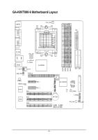
GA-K8VT890-9 Motherboard Layout MS/KB CPU_FAN ATX Socket 939 COMA LPT LAN COMB R_USB ATX_12V USB AUDIO F_AUDIO SUR_CEN Marvell 8053 CD_IN PCIE_16 VIA K8T890 CODEC SPDIF_IO IT8705 PCI1 PCI2 BIOS PCI3 PCIE_1 PCIE_2 GA-K8VT890-9 DDR1 DDR2 DDR3 DDR4 IDE1 IDE2 FDD VIA VT8237R SATA1 - Gigabyte GA-K8VT890-9 | User Manual - Page 7
Block Diagram 1 PCI Express x 16 Port PCI-ECLK (100MHz) PCI Express x16 AMD K8 Socket 939 CPU CPUCLK+/-(200MHz) DDR 400/333/266/200MHz DIMM Dual Channel Memory Hyper Transport Bus 2 PCI Express x 1 Ports PCI-ECLK (100MHz) PCI Express x1 Marvell 8053 - Gigabyte GA-K8VT890-9 | User Manual - Page 8
- 8 - - Gigabyte GA-K8VT890-9 | User Manual - Page 9
instructions below: 1. Please turn off the computer and unplug its power cord. 2. When handling the motherboard , avoid touching any metal leads or connectors. 3. It is best to wear an electrostatic discharge (ESD) cuff when handling electronic components (CPU motherboard problem manual - Gigabyte GA-K8VT890-9 | User Manual - Page 10
English 1-2 Feature Summary CPU Chipset Memory Slots IDE Connections FDD Connections Onboard SATA Peripherals Onboard LAN Onboard Audio I/O Control Hardware Monitor Š Socket 939 for AMD AthlonTM 64 / 64FX processor (K8) Š 2000MHz system bus Š Supports core frequencies in excess of 3000+ and - Gigabyte GA-K8VT890-9 | User Manual - Page 11
Onboard SATA RAID Š BIOS Š Š Additional Features Š Š Overclocking Š Š Form Factor Š Onboard VT8237R chipset (SATA0, SATA1) - supports data striping (RAID 0) or mirroring (RAID 1) or JBOD function - supports data transfer rate of up to 150 MB/s - supports hot plugging function - supports - Gigabyte GA-K8VT890-9 | User Manual - Page 12
down on the middle of the CPU and gently press the metal lever back into its original position. Please use extra care when installing the CPU. The CPU will not fit if positioned incorrectly. Rather than applying force, please change the positioning of the CPU. GA-K8VT890-9 Motherboard - 12 - - Gigabyte GA-K8VT890-9 | User Manual - Page 13
sink paste on the surface of the CPU. Install all the heat sink components (Please refer to the heat sink manual for detailed installation instructions). Fig.2 Please connect the heat sink power connector to the CPU_FAN connector located on the motherboard so that the heat sink can properly function - Gigabyte GA-K8VT890-9 | User Manual - Page 14
fit in one direction. Insert the DIMM memory module vertically into the DIMM socket. Then push it down. Fig.2 Close the plastic clip at both edges of the DIMM sockets to lock the DIMM module. Reverse the installation steps when you wish to remove the DIMM module. GA-K8VT890-9 Motherboard - 14 - - Gigabyte GA-K8VT890-9 | User Manual - Page 15
English Dual Channel Memory Configuration The GA-K8VT890-9 supports the Dual Channel Technology. When the Dual Channel Technology is activated, the bandwidth of memory bus will be double the original one. Due to CPU limitation, if you want to operate the Dual Channel Technology, please follow the - Gigabyte GA-K8VT890-9 | User Manual - Page 16
outlined below: 1. Read the related expansion card's instruction document before install the expansion card into the computer the computer, if necessary, setup BIOS utility of expansion card from BIOS. 8. Install related driver from the operating system. Installing a GA-K8VT890-9 Motherboard - 16 - - Gigabyte GA-K8VT890-9 | User Manual - Page 17
USB controller. If your OS does not support USB controller, please contact OS vendor for possible patch or driver upgrade. For more information please contact your OS or device(s) vendors. LAN Port The provided Internet connection is Gigabit Ethernet, providing data transfer speeds of 10/100 - Gigabyte GA-K8VT890-9 | User Manual - Page 18
1 3 2 11 13 12 14 1) ATX_12V 2) ATX (Power Connector) 3) CPU_FAN 4) SYS_FAN 5) FDD 6) IDE1 / IDE2 7) SATA0 / SATA1 8) PWR_LED 9) BATTERY 6 7 5 10 8 4 9 15 17 16 10) F_PANEL 11) F_AUDIO 12) CD_IN 13) SUR_CEN 14) SPDIF_IO 15) F_USB1 / F_USB2 16) CLR_CMOS 17) CI GA-K8VT890-9 Motherboard - 18 - Gigabyte GA-K8VT890-9 | User Manual - Page 19
location on the motherboard and connect tightly. The ATX_12V power connector mainly supplies power to the CPU. If the 4 +5V 5 GND 6 +5V 7 GND 8 Power Good 9 5V SB(stand by +5V) 10 +12V 11 +12V 12 3.3V(Only for 24pins ATX) 13 3.3V 1 13 14 -12V 15 GND 16 PS_ON(soft On - Gigabyte GA-K8VT890-9 | User Manual - Page 20
failure. Caution! Please remember to connect the power to the CPU fan to prevent CPU overheating and failure. 1 CPU_FAN Pin No. 1 2 3 supported are: 360KB, 720KB, 1.2MB, 1.44MB and 2.88MB. Please connect the red power connector wire to the pin1 position. 34 33 GA-K8VT890-9 Motherboard 2 - Gigabyte GA-K8VT890-9 | User Manual - Page 21
other as Slave (for information on settings, please refer to the instructions located on the IDE device). 40 39 2 IDE1 1 IDE2 7) provide up to 150MB/s transfer rate. Please refer to the BIOS setting for the Serial ATA and install the proper driver in order to work properly. 1 7 SATA1 1 7 - Gigabyte GA-K8VT890-9 | User Manual - Page 22
1 MPD+ 1 2 MPD- 3 MPD- 9) BATTERY GA-K8VT890-9 Motherboard Danger of explosion if battery is incorrectly replaced. Replace only with the same or equivalent type recommended by the manufacturer. Dispose of used batteries according to the manufacturer's instructions. If you want to erase CMOS - Gigabyte GA-K8VT890-9 | User Manual - Page 23
English 10) F_PANEL (Front Panel Jumper) Please connect the power LED, PC speaker, reset switch and power switch etc. of your chassis front panel to the F_PANEL connector according to the pin assignment below. Speaker Connector Power Switch Message LED/ Power/ Sleep LED SPEAK- 20 19 SPEAK+ PWPW - Gigabyte GA-K8VT890-9 | User Manual - Page 24
Definition MIC GND MIC_BIAS Power Front Audio (R) Rear Audio (R)/ Return R NC No Pin Front Audio (L) Rear Audio (L)/ Return L 12) CD_IN (CD In Connector) Connect CD-ROM or DVD-ROM audio out to the connector. 1 Pin No. Definition 1 CD-L 2 GND 3 GND 4 CD-R GA-K8VT890-9 Motherboard - 24 - - Gigabyte GA-K8VT890-9 | User Manual - Page 25
OUTL SUR OUTR GND No Pin CENTER_OUT BASS_OUT AUX_L AUX_R 14) SPDIF_IO (SPDIF In / Out Connector) The SPDIF output is capable of providing digital audio to external speakers or compressed AC3 data to an external Dolby Digital Decoder. Use this feature only when your stereo system has digital input - Gigabyte GA-K8VT890-9 | User Manual - Page 26
this jumper. To clear CMOS, temporarily short 1-2 pin. Default doesn't include the "Shunter" to prevent from improper use this jumper. 1 Open: Normal 1 Short: Clear CMOS GA-K8VT890-9 Motherboard - 26 - - Gigabyte GA-K8VT890-9 | User Manual - Page 27
English 17) CI (Chassis Intrusion, Case Open) This 2-pin connector allows your system to enable or disable the "case open" item in BIOS if the system case has been remove. Pin No. Definition 1 1 Signal 2 GND - 27 - Hardware Installation - Gigabyte GA-K8VT890-9 | User Manual - Page 28
English GA-K8VT890-9 Motherboard - 28 - - Gigabyte GA-K8VT890-9 | User Manual - Page 29
BIOS, either GIGABYTE's Q-Flash or @BIOS utility can be used. Q-Flash allows the user to quickly and easily update or backup BIOS without entering the operating system. @BIOS is a Windows-based utility that does not require users to boot to DOS before upgrading BIOS but directly download and update - Gigabyte GA-K8VT890-9 | User Manual - Page 30
settings for your motherboard. The Main Menu (For example: BIOS Ver. : D2) Once you enter Award BIOS CMOS Setup Utility, the Main CPU clock and frequency ratio. „ Top Performance If you wish to maximize the performance of your system, set "Top Performance" as "Enabled". GA-K8VT890-9 Motherboard - Gigabyte GA-K8VT890-9 | User Manual - Page 31
system. „ Save & Exit Setup Save CMOS value settings to CMOS and exit setup. „ Exit Without Saving Abandon all CMOS value changes and exit setup. - 31 - BIOS Setup - Gigabyte GA-K8VT890-9 | User Manual - Page 32
Utility KLJI: Move Enter: Select F5: Previous Values 640K 239M 240M Manual User can manually SATA IDE devices setup. You can use one of two methods: • Auto Allows BIOS to automatically detect SATA IDE devices during POST(default) • None Select this if no SATA GA-K8VT890-9 Motherboard - 32 - - Gigabyte GA-K8VT890-9 | User Manual - Page 33
inch double-sided drive; 2.88M byte capacity. Floppy 3 Mode Support (for Japan Area) Disabled Normal Floppy Drive. (Default value) motherboard. Extended Memory The BIOS determines how much extended memory is present during the POST. This is the amount of memory located above 1 MB in the CPU - Gigabyte GA-K8VT890-9 | User Manual - Page 34
English 2-2 Advanced BIOS Features CMOS Setup Utility-Copyright (C) 1984-2004 Award Software Advanced BIOS Features ` Hard Disk Boot Priority First Boot Device Second Boot Device Third Boot Device page if the correct password is not entered at the prompt. GA-K8VT890-9 Motherboard - 34 - - Gigabyte GA-K8VT890-9 | User Manual - Page 35
CMOS Setup Utility-Copyright (C) 1984-2004 Award Software Integrated Peripherals IDE DMA transfer access OnChip IDE Channel0 OnChip IDE Channel1 OnChip Serial ATA SATA Mode AC97 Audio Onboard H/W LAN USB 1.1 Controller USB 2.0 Controller USB Keyboard Support USB Mouse Support Onboard Serial - Gigabyte GA-K8VT890-9 | User Manual - Page 36
Support Enabled Enable USB keyboard support. Disabled Disable USB keyboard support. (Default value) USB Mouse Support Enabled Disabled Enable USB mouse support. Disable USB mouse support. (Default value) Onboard Serial Port 1 Auto 3F8/IRQ4 2F8/IRQ3 BIOS 5. GA-K8VT890-9 Motherboard - 36 - - Gigabyte GA-K8VT890-9 | User Manual - Page 37
2-4 Power Management Setup CMOS Setup Utility-Copyright (C) 1984-2004 Award Software [Disabled] Everyday 0 : 0 : 0 Item Help Menu Level` KLJI: Move Enter: Select F5: Previous Values +/-/PU/PD: Value F10: Save F6: Fail-Safe Defaults ESC: Exit F1: General by mouse event. - 37 - BIOS Setup - Gigabyte GA-K8VT890-9 | User Manual - Page 38
ON system. If RTC Alarm Lead To Power On is Enabled. Date (of Month) Alarm : Everyday, 1~31 Time (hh: mm: ss) Alarm : (0~23) : (0~59) : (0~59) GA-K8VT890-9 Motherboard - 38 - - Gigabyte GA-K8VT890-9 | User Manual - Page 39
[Auto] [Auto] [Auto] Item Help Menu Level` KLJI: Move Enter: Select F5: Previous Values PCI 1 IRQ Assignment Auto 3,4,5,7,9,10,11,12,14,15 PCI 2 IRQ Assignment Auto 3,4,5,7,9,10,11,12,14,15 PCI 3 IRQ Assignment Auto 3,4,5,7,9,10,11,12,14,15 +/-/PU/PD: Value F10: Save F6: Fail-Safe Defaults ESC - Gigabyte GA-K8VT890-9 | User Manual - Page 40
CPU temperature automatically. Current CPU/SYSTEM FAN Speed (RPM) Detect CPU/SYSTEM fan speed status automatically. CPU/SYSTEM FAN Fail Warning Disabled Disable CPU/SYSTEM fan fail warning function. (Default value) Enabled Enable CPU/SYSTEM fan fail warning function. GA-K8VT890-9 Motherboard - Gigabyte GA-K8VT890-9 | User Manual - Page 41
CMOS Setup Utility-Copyright (C) 1984-2004 Award Software Frequency/Voltage Control K8 CPU Clock Ratio Auto Detect PCI/DIMM Clk CPU Clock CPU OverVoltage Control DIMM OverVoltage Control [Default] [Enabled] [200MHz] [Auto] [Auto] Item Help Menu Level` KLJI: Move Enter: Select F5: Previous Values - Gigabyte GA-K8VT890-9 | User Manual - Page 42
XP, but works smoothly with Windows NT. Therefore, if your system is not perform enough, the reliability or stability problem will appear sometimes, and we will recommend you disabling the option to avoid the problem as mentioned above. 2-9 Load Fail-Safe Defaults CMOS Setup Utility-Copyright - Gigabyte GA-K8VT890-9 | User Manual - Page 43
Item F10: Save & Exit Setup Load Optimized Defaults Selecting this field loads the factory defaults for BIOS and Chipset Features which the system automatically detects. 2-11 Set Supervisor/User Password CMOS Setup Utility-Copyright (C) 1984-2004 Award Software ` Standard CMOS Features ` Advanced - Gigabyte GA-K8VT890-9 | User Manual - Page 44
to Setup Utility. 2-13 Exit Without Saving CMOS Setup Utility-Copyright (C) 1984-2004 Award Software ` Standard CMOS Features ` Advanced BIOS Features ` Type "Y" will quit the Setup Utility without saving to RTC CMOS. Type "N" will return to Setup Utility. GA-K8VT890-9 Motherboard - 44 - - Gigabyte GA-K8VT890-9 | User Manual - Page 45
in Windows XP. Insert the driver CD-title that came with your motherboard into your CD-ROM drive, the driver CD-title will auto start and show the installation guide. If not, please double click the CD-ROM device icon in "My computer", and execute the Setup.exe. 3-1 Install Chipset Drivers After - Gigabyte GA-K8VT890-9 | User Manual - Page 46
English 3-2 Software Application This page displays all the tools that GIGABYTE developed and some free software. You can click an item to install it. 3-3 Software Information This page lists the contents of software and drivers in this CD-title. GA-K8VT890-9 Motherboard - 46 - - Gigabyte GA-K8VT890-9 | User Manual - Page 47
English 3-4 Hardware Information This page lists all device you have for this motherboard. 3-5 Contact Us Please see the last page for details. - 47 - Drivers Installation - Gigabyte GA-K8VT890-9 | User Manual - Page 48
English GA-K8VT890-9 Motherboard - 48 - - Gigabyte GA-K8VT890-9 | User Manual - Page 49
EasyTune 5 presents the most convenient Windows based system performance enhancement and manageability utility. Featuring several powerful yet easy to use tools such as 1) Overclocking for enhancing system performance, 2) C.I.A. and M.I.B. for special enhancement for CPU and Memory, 3) Smart-Fan - Gigabyte GA-K8VT890-9 | User Manual - Page 50
power on. . . Verifying DMI Pool Data Boot from CD: Boot from CD: Xpress Recovery V1.0 (C) Copy Right 2003. GIGABYTE Technology CO. , Ltd. 1. Execute Backup Utility 2. Execute Restore Utility 3. Remove Backup Image 4. Set Password 5. Exit and Restart Build 2011 GA-K8VT890-9 Motherboard - 50 - - Gigabyte GA-K8VT890-9 | User Manual - Page 51
865PE AGPSet BIOS for 8IPE1000MT F1 Check System Health OK . . . Press DEL to enter SETUP / Q-Flash, F9 For Xpress Recovery 08/16/2002-I845GE-6A69YG01C-00 F9 For Xpress Recovery Xpress Recovery V1.0 (C) Copy Right 2003. GIGABYTE Technology CO. , Ltd. 1. Execute Backup Utility 2. Execute Restore - Gigabyte GA-K8VT890-9 | User Manual - Page 52
System or Esc to Exit The backup utility will automatically scan your system and back up data as a backup image in your hard drive. Not all systems support access to Xpress Recovery by pressing the requirement. 5. Exit and Restart: Exit and restart your computer. GA-K8VT890-9 Motherboard - 52 - - Gigabyte GA-K8VT890-9 | User Manual - Page 53
refer to Part Two. Part One: Updating BIOS with Q-FlashTM Utility on Dual BIOS Motherboards. Some of Gigabyte motherboards are equipped with dual BIOS. In the BIOS menu of the motherboards supporting Q-Flash and Dual BIOS, the Q-Flash utility and Dual BIOS utility are combined in the same screen - Gigabyte GA-K8VT890-9 | User Manual - Page 54
Enter key on your keyboard to enable execution of the task. Action bar: Contains the names of four actions needed to operate the Q-Flash/Dual BIOS utility. Pressing the buttons mentioned on your keyboards to perform these actions. GA-K8VT890-9 Motherboard - 54 - - Gigabyte GA-K8VT890-9 | User Manual - Page 55
flash and press Enter. In this example, we only download one BIOS file to the floppy disk so only one BIOS file, 8KNXPU.Fba, is listed. Please confirm again you have the correct BIOS file for your motherboard. Dual BIOS Utility Boot From Main Bios Main ROM Type/Size SST 49LF004A Backup ROM Type - Gigabyte GA-K8VT890-9 | User Manual - Page 56
begins flashing BIOS. 4. Press any keys to return to the Q-Flash menu when the BIOS updating procedure is completed. Dual BIOS Utility Boot From Main Bios Main ROM DEL to enter SETUP / Dual BIOS / Q-Flash / F9 For Xpress Recovery 09/23/2003-i875P-6A79BG03C-00 GA-K8VT890-9 Motherboard - 56 - - Gigabyte GA-K8VT890-9 | User Manual - Page 57
your keyboard to save and exit. Part Two: Updating BIOS with Q-FlashTM Utility on Single-BIOS Motherboards. This part guides users of single-BIOS motherboards how to update BIOS using the Q-FlashTM utility. CMOS Setup Utility-Copyright (C) 1984-2004 Award Software Standard CMOS Features Advanced - Gigabyte GA-K8VT890-9 | User Manual - Page 58
SyCs:tRemeset F10:Power Off Do not trun off power or reset your system at this stage!! After BIOS file is read, you'll see a confirmation dialog box asking you "Are you sure to update BIOS?" Please do not take out the floppy disk when it begins flashing BIOS. GA-K8VT890-9 Motherboard - 58 - - Gigabyte GA-K8VT890-9 | User Manual - Page 59
trun off power or reset your system at this stage!! 4. Press any keys to return to the Q-Flash menu when the BIOS updating procedure is completed. Q-Flash Utility V1.30 Flash Type/Size SST 49LF003A 256K Enter : Run Keep DMI Data Enable !! CopUypBdaItOe SBIcOomS pfrloemtedFl-oPppayss !! Save - Gigabyte GA-K8VT890-9 | User Manual - Page 60
. b. Click "Update New BIOS". c. Please select "All Files" in dialog box while opening the old file. d. Please search for BIOS unzip file, downloading from internet or any other methods (such as: K8VT8909.D2). e. Complete update process following the instruction. GA-K8VT890-9 Motherboard - 60 - - Gigabyte GA-K8VT890-9 | User Manual - Page 61
II, be sure that motherboard's model name in BIOS unzip file are the same as your motherboard's. Otherwise, your system won't boot. III. In method I, if the BIOS file you need cannot be found in @BIOSTM server, please go onto Gigabyte's website for downloading and updating it according to method II - Gigabyte GA-K8VT890-9 | User Manual - Page 62
4-1-4 Serial ATA BIOS Setting Utility Introduction RAID Levels RAID (Redundant Array of costs. The RAID levels which the VIA VT8237R chipset supports are RAID 0, RAID 1,and JBOD. RAID 0 (Striping) RAID 0 reads not really a RAID and does not support fault tolerance. GA-K8VT890-9 Motherboard - 62 - - Gigabyte GA-K8VT890-9 | User Manual - Page 63
driver installation. 6) Complete RAID utility installation. More information on steps 4 and 5 is provided. (For more detailed setup information, please visit our website at http:\\www.gigabyte.com.tw to read or download the information you need.) Configuring the VT8237(VT8237R) SATA RAID BIOS - Gigabyte GA-K8VT890-9 | User Manual - Page 64
Drive Name ST3120026AS ST3120026AS Create a RAID array with the hard disks attached to VIA RAID controller F1 : View Array/disk Status , : Move to next item Enter : Confirm the selection ESC : Exit Array Name Mode SATA SATA Size(GB) 111.79 111.79 Status Hdd Hdd GA-K8VT890-9 Motherboard - 64 - - Gigabyte GA-K8VT890-9 | User Manual - Page 65
select a block size from the popup menu. The block size can be 4KB to 64KB. VIA Tech. VT8237 SATA RAID BIOS Ver 2.31 Auto Setup For Performance Array Mode RAID 0 (Strip4inKg) Select Disk Drives 8K Block Size 64K 16K Start Create Process 32K 64K Channel Drive Name [*]Serial_Ch0 Master - Gigabyte GA-K8VT890-9 | User Manual - Page 66
mark and press Enter, its boot setting will be canceled. VIA Tech. VT8237 SATA RAID BIOS Ver 2.31 Create Array Delete Array Create/Delete Spare Select Boot Array Serial Array Name ARRAY 0 ARRAY 0 Mode SATA SATA Size(GB) 111.79 111.79 Status Boot Boot GA-K8VT890-9 Motherboard - 66 - - Gigabyte GA-K8VT890-9 | User Manual - Page 67
the selected drive's serial number can be viewed in the last column. The serial number is assigned by the disk drive manufacturer. VIA Tech. VT8237 SATA RAID BIOS Ver 2.31 Create Array Delete Array Create/Delete Spare Select Boot Array Serial Number View View the serial number of hard disk, it is - Gigabyte GA-K8VT890-9 | User Manual - Page 68
and insert the GIGABYTE motherboard drive CD-ROM. From the CDROM drive (example: D:\) double click the MENU.exe file in the BootDrv folder. A command prompt window will open similar to that in Fig. 2. (Note2) In the menu list, Intel IAA_RAID is Intel ICH5R chipset. GA-K8VT890-9 Motherboard - 68 - - Gigabyte GA-K8VT890-9 | User Manual - Page 69
pictures are in Windows XP). Please note that if you want to set up an 8 channel audio configuration, you must use Audio Combo Kit (optional Line Out". Line Out STEP 2: Following installation of the audio driver, you'll will find a Sound Effect icon on the lower right hand taskbar. Click the - Gigabyte GA-K8VT890-9 | User Manual - Page 70
Out", the Rear Speakers to "Line In". STEP 2: Following installation of the audio driver, you'll find a Sound Effect icon on the lower right hand taskbar. Click the icon to select the function bar and select "4CH Speaker" to complete 4 channel audio configuration. GA-K8VT890-9 Motherboard - 70 - - Gigabyte GA-K8VT890-9 | User Manual - Page 71
to "Line Out", the Rear Speakers to "Line In", and the Center/Subwoofer Speakers to "MIC In". STEP 2: Following installation of the audio driver, you'll find a Sound Effect icon on the lower right hand taskbar. Click the icon to select the function. Line In (Rear Speaker Out) Line Out (Front - Gigabyte GA-K8VT890-9 | User Manual - Page 72
Connect the front channels to the "Line Out" port located on the audio panel and the rear channels to the Surround-Kit "REAR R/L" port. Connect the center/subwoofer channels to the Surround-Kit "SUB CENTER" and the R/L channels to the Surround-Kit "SUR BACK" port. GA-K8VT890-9 Motherboard - 72 - - Gigabyte GA-K8VT890-9 | User Manual - Page 73
and the R/L channels to the Surround-Kit "SUR BACK" port. (This method requires UAJ function) STEP 4: Following installation of the audio driver, you'll find a Sound Effect icon on the lower right hand taskbar. Click the icon to select the function. STEP 5: Click "Speaker Configuration" and select - Gigabyte GA-K8VT890-9 | User Manual - Page 74
it with screw. 2. Connect SPDIF device to the motherboard. 3. Connect SPDIF to the SPDIF decoder. (Note) If you want to use both of the 8 channel audio function and SPDIF out function, you may buy the Audio Combo Kit (refer to the 8 channel Audio Setup section). GA-K8VT890-9 Motherboard - 74 - - Gigabyte GA-K8VT890-9 | User Manual - Page 75
.1 or later version before to enable Jack-Sensing support for Windows 2000. Jack-Sensing includes 2 parts: AUTO and MANUAL. (Following pictures are in Windows XP): Introduction of audio connectors You may connect CDROM, Walkman or others audio input devices to Line In jack, speakers, earphone - Gigabyte GA-K8VT890-9 | User Manual - Page 76
jack (Line-in/ Line-out). That means users do not need to worry the audio device should be plug in Line-in or Line-out jack, the device will work perfectly after UAJ is activated. Enable UAJ function: You can click "UAJ Automatic" button to enable UAJ function. GA-K8VT890-9 Motherboard - 76 - - Gigabyte GA-K8VT890-9 | User Manual - Page 77
Troubleshooting Below is a collection of general asked questions. To check general asked questions based on a specific motherboard model, please log on to http://www.gigabyte.com.tw Question 1: I cannot see some options that were included in previous BIOS after updating BIOS in the manual. If your - Gigabyte GA-K8VT890-9 | User Manual - Page 78
English GA-K8VT890-9 Motherboard - 78 - - Gigabyte GA-K8VT890-9 | User Manual - Page 79
.giga-byte.com U.S.A. G.B.T. INC. TEL: +1-626-854-9338 FAX: +1-626-854-9339 Tech. Support : http://tw.giga-byte.com/TechSupport/ServiceCenter.htm Non-Tech. Support(Sales/Marketing) : http://ggts.gigabyte.com.tw/nontech.asp WEB address : http://www.giga-byte.com Germany G.B.T. TECHNOLOGY TRADING GMBH - Gigabyte GA-K8VT890-9 | User Manual - Page 80
.gigabyte.cz Romania Representative Office Of GIGA-BYTE Technology Co., Ltd. in Romania Tech. Support : http://tw.giga-byte.com/TechSupport/ServiceCenter.htm Non-Tech. Support(Sales/Marketing) : http://ggts.gigabyte.com.tw/nontech.asp WEB address: http://www.gigabyte.com.ro GA-K8VT890-9 Motherboard
-
 1
1 -
 2
2 -
 3
3 -
 4
4 -
 5
5 -
 6
6 -
 7
7 -
8
-
9
-
10
-
11
-
12
-
13
-
14
-
15
-
16
-
17
-
18
-
19
-
20
-
21
-
22
-
23
-
24
-
25
-
26
-
27
-
28
-
29
-
30
-
31
-
32
-
33
-
34
-
35
-
36
-
37
-
38
-
39
-
40
-
41
-
42
-
43
-
44
-
45
-
46
-
47
-
48
-
49
-
50
-
51
-
52
-
53
-
54
-
55
-
56
-
57
-
58
-
59
-
60
-
61
-
62
-
63
-
64
-
65
-
66
-
67
-
68
-
69
-
70
-
71
-
72
-
73
-
74
-
75
-
76
-
77
-
78
-
79
-
80
 |
 |

GA-K8VT890-9
AMD Socket 939 Processor Motherboard
User's Manual
Rev. 1003
12ME-K8VT8909-1003