Gigabyte GA-M51GM-S2G Manual
Gigabyte GA-M51GM-S2G Manual
 |
UPC - 818313002914
View all Gigabyte GA-M51GM-S2G manuals
Add to My Manuals
Save this manual to your list of manuals |
Gigabyte GA-M51GM-S2G manual content summary:
- Gigabyte GA-M51GM-S2G | Manual - Page 1
GA-M51GM-S2G AMD Socket AM2 Processor Motherboard User's Manual Rev. 1002 12ME-M51GMS2G-1002R * The WEEE marking on the product indicates this product must not be disposed of with user's other household waste and must - Gigabyte GA-M51GM-S2G | Manual - Page 2
Motherboard GA-M51GM-S2G May. 10, 2006 Motherboard GA-M51GM-S2G May. 10, 2006 - Gigabyte GA-M51GM-S2G | Manual - Page 3
product information and specifications, please carefully read the "Product User Manual". „ For detailed information related to Gigabyte's unique features, please go to "Technology Guide" section on Gigabyte's website to read or download the information you need. For more product details, please - Gigabyte GA-M51GM-S2G | Manual - Page 4
OptionalAccessories ...6 GA-M51GM-S2G Motherboard Layout 7 Block Diagram ...8 Chapter 1 Hardware Installation 9 1-1 Considerations Prior to Installation 9 1-2 Feature Summary 10 1-3 Installation of the CPU and CPU Cooler 12 1-3-1 Installation of the CPU 12 1-3-2 Installation of the CPU cooler - Gigabyte GA-M51GM-S2G | Manual - Page 5
4 Appendix 53 4-1 Unique Software Utilities 53 4-1-1 EasyTune 5 Introduction 53 4-1-2 Xpress Recovery2 Introduction 54 4-1-3 Flash BIOS Method Introduction 56 4-1-4 Configuring SATA Hard Drive(s 65 4-1-5 2- / 4- / 6- / 8- Channel Audio Function Introduction 79 4-2 Troubleshooting 83 - 5 - - Gigabyte GA-M51GM-S2G | Manual - Page 6
Item Checklist IDE Cable x 1 & FDD Cable x 1 Serial ATAII Cable x 2 I/O Shield * The items listed above are for reference only, and are subject to change without notice. Optional Accessories Š 2 Ports USB2.0 Cable (Part Number: 12CR1-1UB030-51/ 51R) Š 4 Ports USB2.0 Cable (Part Number: 12CR1-1UB030- - Gigabyte GA-M51GM-S2G | Manual - Page 7
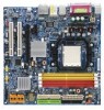
GA-M51GM-S2G Motherboard Layout MS / KB ATX_12V GA-M51GM-S2G ATX FDD COMA LPT VGA USB USB 1394 LAN CPU_FAN Socket AM2 IT8716 AUDIO F_AUDIO CI BIOS PCIE_1 Marvell 88E1116 PCIE_16 PCI1 CD_IN PCI2 CODEC SPDIF_IO COMB nVIDIA® GeForce 6100 TSB43AB23 BATTERY CLR_CMOS nVIDIA® nForce 430 - Gigabyte GA-M51GM-S2G | Manual - Page 8
1 LAN RJ45 Marvell 88E1116 PCI Bus TSB43AB23 AMD Socket AM2 CPU CPUCLK+/-(200MHz) DDRII 800/667/533/400MHz DIMM Dual Channel Memory Hyper Transport Bus nVIDIA® GeForce 6100 nVIDIA® nForce 430 ATA33/66/100/133 IDE Channels 4 SATA 3Gb/s BIOS LPC BUS IT8716 Floppy LPT Port COM Ports CODEC - Gigabyte GA-M51GM-S2G | Manual - Page 9
instructions below: 1. Please turn off the computer and unplug its power cord. 2. When handling the motherboard , avoid touching any metal leads or connectors. 3. It is best to wear an electrostatic discharge (ESD) cuff when handling electronic components (CPU motherboard problem manual - Gigabyte GA-M51GM-S2G | Manual - Page 10
connectors Š 1 CPU fan connector Š 1 system fan connector Š 1 front panel connector Š 1 front audio connector Š 1 CD In connector Š 2 USB 2.0/1.1 connectors for additional 4 USB 2.0/1.1 ports by cables Š 2 IEEE1394a connectors for additional 2 port by cable GA-M51GM-S2G Motherboard - 10 - - Gigabyte GA-M51GM-S2G | Manual - Page 11
speed detection Š CPU warning temperature Š CPU / System fan failure warning Š Supports CPU / System Smart Fan function(Note 2) BIOS Š 1 4Mbit flash ROM Š Use of licensed AWARD BIOS Additional Features Š Supports @BIOS Š Supports Download Center Š Supports Q-Flash Š Supports EasyTune (only - Gigabyte GA-M51GM-S2G | Manual - Page 12
on the middle of the CPU and gently press themetal lever back into its original position. Pin One Please use extra care when installing the CPU. The CPU will not fit if positioned incorrectly. Rather than applying force, please change the positioning of the CPU. GA-M51GM-S2G Motherboard - 12 - - Gigabyte GA-M51GM-S2G | Manual - Page 13
refer to the heat sink manual for detailed installation instructions). Fig.2 Please connect the CPU cooler power connector to the CPU_FAN connector located on the motherboard so that the CPU cooler can properly function to prevent CPU overheating. The CPU cooler may adhere to the CPU as a result of - Gigabyte GA-M51GM-S2G | Manual - Page 14
. The motherboard supports DDR II memory modules, whereby BIOS will automatically socket. Then push it down. Fig.2 Close the plastic clip at both edges of the DIMM sockets to lock the DIMM module. Reverse the installation steps when you wish to remove the DIMM module. GA-M51GM-S2G Motherboard - Gigabyte GA-M51GM-S2G | Manual - Page 15
GA-M51GM-S2G supports the Dual Channel Technology. After operating the Dual Channel Technology, the bandwidth of Memory Bus will add double. Due to CPU you must install them into DIMM sockets of the same color. 3. To DDR II 1 DS/SS - DS/SS DDR II 2 DS/SS - DS/SS DDR II 3 - DS/SS DS/SS DDR II 4 - Gigabyte GA-M51GM-S2G | Manual - Page 16
outlined below: 1. Read the related expansion card's instruction document before install the expansion card into the computer the computer, if necessary, setup BIOS utility of expansion card from BIOS. 8. Install related driver from the operating system. Installing a GA-M51GM-S2G Motherboard - 16 - - Gigabyte GA-M51GM-S2G | Manual - Page 17
device(s) such as USB keyboard, mouse, scanner, zip, speaker...etc. have a standard USB interface. Also make sure your OS supports USB controller. If your OS does not support USB controller, please contact OS vendor for possible patch or driver upgrade. For more information please contact your OS - Gigabyte GA-M51GM-S2G | Manual - Page 18
speakers settings, the ~ audio jacks can be reconfigured to perform different functions via the audio software. Only microphones still 5) FDD 6) IDE1 / IDE2 7) SATAII0_1 / SATAII2_3 8) F_PANEL 9) CD_IN GA-M51GM-S2G Motherboard 10) F_AUDIO 11) F_USB1 / F_USB2 12) POWER_LED 13) CI 14) CLR_CMOS - Gigabyte GA-M51GM-S2G | Manual - Page 19
all components and devices are properly installed. Align the power connector with its proper location on the motherboard and connect tightly. The ATX_12V power connector mainly supplies power to the CPU. If the ATX_12V power connector is not connected, the system will not start. Caution! Please use - Gigabyte GA-M51GM-S2G | Manual - Page 20
to connect the CPU/system fan cable to the CPU_FAN/SYS_FAN connector to prevent CPU damage or system hanging supported are: 360KB, 720KB, 1.2MB, 1.44MB and 2.88MB. Before attaching the FDD cable, please take note of the foolproof groove in the FDD connector. 34 33 2 1 GA-M51GM-S2G Motherboard - Gigabyte GA-M51GM-S2G | Manual - Page 21
as Slave (for information on settings, please refer to the instructions located on the IDE device). Before attaching the IDE cable, up to 300MB/s transfer rate. Please refer to the BIOS setting for the Serial ATA and install the proper driver in order to work properly. SATAII 2 SATAII 0 SATAII2_3 - Gigabyte GA-M51GM-S2G | Manual - Page 22
Hardware System Open: Normal Close: Power On/Off Pin 1: LED anode(+) Pin 2: LED cathode(-) NC 9) CD_IN (CD In Connector) Connect CD-ROM or DVD-ROM audio out to the connector. 1 Pin No. Definition 1 CD-L 2 GND 3 GND 4 CD-R GA-M51GM-S2G Motherboard - 22 - - Gigabyte GA-M51GM-S2G | Manual - Page 23
Pin 8 No Pin 9 LINE2_L 9 Line Out (L) 10 FSENSE2 10 NC By default, the audio driver is configured to support HD Audio. To connect an AC97 front panel audio module to this connector, please refer to the instructions on Page 79 about the software settings. 11) F_ USB1 / F_USB2 (Front USB - Gigabyte GA-M51GM-S2G | Manual - Page 24
Intrusion, Case Open) This 2-pin connector allows your system to detect if the chassis cover is removed. You can check the "Case Opened" status in BIOS Setup. Pin No. Definition 1 1 Signal 2 GND GA-M51GM-S2G Motherboard - 24 - - Gigabyte GA-M51GM-S2G | Manual - Page 25
is incorrectly replaced. Replace only with the same or equivalent type recommended by the manufacturer. Dispose of used batteries according to the manufacturer's instructions. If you want to erase CMOS... 1. Turn off the computer and unplug the power cord. 2. Gently take out the battery and put it - Gigabyte GA-M51GM-S2G | Manual - Page 26
Pin 10 GND 17) SPDIF_IO (SPDIF In/Out) The SPDIF output is capable of providing digital audio to external speakers or compressed AC3 data to an external Dolby Digital Decoder. Use this feature only 1 6 2 1 Power 2 No Pin 3 SPDIF 4 SPDIFI 5 GND 6 GND GA-M51GM-S2G Motherboard - 26 - - Gigabyte GA-M51GM-S2G | Manual - Page 27
English 18) COMB (COMB Connector) Be careful with the polarity of the COMB connector. Check the pin assignment carefully while you connect the COMB cable, incorrect connection between the cable and connector will make the device unable to work or even damage it. For optional COMB cable, please - Gigabyte GA-M51GM-S2G | Manual - Page 28
English GA-M51GM-S2G Motherboard - 28 - - Gigabyte GA-M51GM-S2G | Manual - Page 29
BIOS, either GIGABYTE's Q-Flash or @BIOS utility can be used. Q-Flash allows the user to quickly and easily update or backup BIOS without entering the operating system. @BIOS is a Windows-based utility that does not require users to boot to DOS before upgrading BIOS but directly download and update - Gigabyte GA-M51GM-S2G | Manual - Page 30
motherboard. If you can't find the setting you want, please press "Ctrl+F1" to search the advanced option hidden.Please Load Optimized Defaults in the BIOS when somehow the system works not stable as usual. This action makes the system reset to the default for stability. GA-M51GM-S2G Motherboard - Gigabyte GA-M51GM-S2G | Manual - Page 31
English „ Standard CMOS Features This setup page includes all the items in standard compatible BIOS. „ Advanced BIOS Features This setup page includes all the items of Award special enhanced features. „ Integrated Peripherals This setup page includes all onboard peripherals. „ Power Management - Gigabyte GA-M51GM-S2G | Manual - Page 32
Dec. Drive A Floppy 3 Mode Support Halt On Base Memory Extended Memory determined by the BIOS and is Manual User can manually input the correct settings Access Mode Use this to set the access mode for the hard drive. The four options are: CHS/LBA/Large/Auto(default:Auto) GA-M51GM-S2G Motherboard - Gigabyte GA-M51GM-S2G | Manual - Page 33
3.5" 3.5 inch double-sided drive; 2.88M byte capacity. Floppy 3 Mode Support (for Japan Area) Disabled Normal Floppy Drive. (Default value) Drive that may be detected and you will be prompted. All Errors Whenever the BIOS detects a non-fatal error the system will be stopped. All, But - Gigabyte GA-M51GM-S2G | Manual - Page 34
memory installed on the motherboard. Extended Memory The BIOS determines how much extended memory is present during the POST. This is the amount of memory located above 1 MB in the CPU's memory address map. Total Memory This item displays the memory size that used. GA-M51GM-S2G Motherboard - 34 - - Gigabyte GA-M51GM-S2G | Manual - Page 35
(or add-on cards) SCSI, RAID, etc. Use < > or ZIP. USB-CDROM Select your boot device priority by USB-CDROM. USB-HDD Select your boot device priority by USB-HDD. Legacy LAN Select your boot device priority by Legacy LAN. Disabled Disable this function. Boot Up Floppy Seek During POST, BIOS - Gigabyte GA-M51GM-S2G | Manual - Page 36
display from which card when you install a PCI card and a PCI Express VGA card on the motherboard. PCI Slot Onboard VGA Set Init Display First to PCI VGA card. Set Init Display First to onboard installed. (Default value) Always output from the onboard GPU. GA-M51GM-S2G Motherboard - 36 - - Gigabyte GA-M51GM-S2G | Manual - Page 37
RAID x SATA-II 2 Secondary RAID [Disabled] [Enabled] Disabled Disabled [Enabled] Disabled Disabled Item Help Menu Level` KLJI: Move Enter: Select F5: Previous Values +/-/PU/PD: Value F10: Save F6: Fail-Safe Defaults ESC: Exit F1: General Help F7: Optimized Defaults - 37 - BIOS Setup - Gigabyte GA-M51GM-S2G | Manual - Page 38
. (Default value) Onboard Audio Function Auto Disabled Auto-detect onboard audio function. (Default value) Disable this function. Onboard LAN Function Auto Auto-detect onboard LAN chip function.(Default value) Disabled Disable onboard LAN chip function. GA-M51GM-S2G Motherboard - 38 - - Gigabyte GA-M51GM-S2G | Manual - Page 39
Defaults This motherboard incorporates cable 1. If no cable problem is detected on the LAN figure above. 2. If no cable problem is detected on the LAN cable connected Cable Problem Occurs... If a cable problem occurs on motherboard, the Status fields of all four pairs of wires will show Open. - 39 - Gigabyte GA-M51GM-S2G | Manual - Page 40
and address is 2E8/IRQ3. Disabled Disable onboard Serial port 1. Onboard Serial Port 2 Auto 3F8/IRQ4 BIOS will automatically setup the port 2 address. Enable onboard Serial port 2 and address is 3F8/IRQ4. Port. ECP+EPP Using Parallel port as ECP and EPP mode. GA-M51GM-S2G Motherboard - 40 - - Gigabyte GA-M51GM-S2G | Manual - Page 41
POWER ON system. If Power-On by Alarm is Enabled. Day of Month Alarm : Everyday, 1~31 Time (hh: mm: ss) Alarm : (0~23) : (0~59) : (0~59) - 41 - BIOS Setup - Gigabyte GA-M51GM-S2G | Manual - Page 42
system, the system will be in "Off" state. (Default value) Full-On When AC-power back to the system, the system always in "On" state. GA-M51GM-S2G Motherboard - 42 - - Gigabyte GA-M51GM-S2G | Manual - Page 43
IRQ 3,4,5,7,9,10,11,12,14,15 to PCI 1. Auto assign IRQ to PCI 2. (Default value) Set IRQ 3,4,5,7,9,10,11,12,14,15 to PCI 2. - 43 - BIOS Setup - Gigabyte GA-M51GM-S2G | Manual - Page 44
. CPU Smart FAN Control (Note) Disabled Disable this function. Enabled When this function is enabled, CPU fan will run at different speed depending on CPU temperature. Users can adjust the fan speed with Easy Tune based on their requirements. (Default value) GA-M51GM-S2G Motherboard - 44 - Gigabyte GA-M51GM-S2G | Manual - Page 45
will run at different speed depending on system temperature. Users can adjust the fan speed with Easy Tune based on their requirements. (Note) Whether the CPU Smart FAN Control function is supported will depend on the CPU you install. - 45 - BIOS Setup - Gigabyte GA-M51GM-S2G | Manual - Page 46
(C) 1984-2006 Award Software ` Standard CMOS Features ` Advanced BIOS Features ` Integrated Peripherals ` Power Management Setup ` PnP/PCI Selecting this field loads the factory defaults for BIOS and Chipset Features which the system automatically detects. GA-M51GM-S2G Motherboard - 46 - - Gigabyte GA-M51GM-S2G | Manual - Page 47
the system will boot and you can enter Setup freely. The BIOS Setup program allows you to specify two separate passwords: SUPERVISOR PASSWORD and only basic items. If you select "System" at "Password Check" in Advance BIOS Features Menu, you will be prompted for the password every time the system is - Gigabyte GA-M51GM-S2G | Manual - Page 48
CMOS Setup Utility-Copyright (C) 1984-2006 Award Software ` Standard CMOS Features ` Advanced BIOS Features ` Integrated Peripherals ` Power Management Setup ` PnP/PCI Configurations ` PC Health without saving to RTC CMOS. Type "N" will return to Setup Utility. GA-M51GM-S2G Motherboard - 48 - - Gigabyte GA-M51GM-S2G | Manual - Page 49
shown in Windows XP. Insert the driver CD-title that came with your motherboard into your CD-ROM drive, the driver CD-title will auto start and show the installation guide. If not, please double click the CD-ROM device icon in "My computer", and execute the Run.exe. 3-1 Install Chipset Drivers After - Gigabyte GA-M51GM-S2G | Manual - Page 50
Applications This page displays all the tools that Gigabyte developed and some free software, you can choose anyone you want and press "install" to install them. 3-3 Driver CD Information This page lists the contents of software and drivers in this CD-title. GA-M51GM-S2G Motherboard - 50 - - Gigabyte GA-M51GM-S2G | Manual - Page 51
English 3-4 Hardware Information This page lists all device you have for this motherboard. 3-5 Contact Us Please see the last page for details. - 51 - Drivers Installation - Gigabyte GA-M51GM-S2G | Manual - Page 52
English GA-M51GM-S2G Motherboard - 52 - - Gigabyte GA-M51GM-S2G | Manual - Page 53
yet easy to use tools such as 1) Overclocking for enhancing system performance, 2) C.I.A. and M.I.B. for special enhancement for CPU and Memory, 3) Smart-Fan control for managing fan speed control of both CPU cooling fan and North-Bridge Chipset cooling fan, 4) PC health for monitoring system - Gigabyte GA-M51GM-S2G | Manual - Page 54
of hard disk data. Supporting Microsoft operating systems including Windows XP/2000/NT/98/Me and BIOS Setup, go to Advanced BIOS Feature and set to boot from CD-ROM. Save the settings and exit the BIOS Setup. Insert the provided driver drivers as well as software. GA-M51GM-S2G Motherboard - 54 - - Gigabyte GA-M51GM-S2G | Manual - Page 55
Windows 2000, be sure to execute the EnableBigLba.exe program from the driver CD before data backup. 2. It is normal that data backup takes longer time than data restoration. 3. Xpress Recovery2 is compliant with the GPL regulations. 4. On a few motherboards based on Nvidia chipsets, BIOS update - Gigabyte GA-M51GM-S2G | Manual - Page 56
Primary Master : FUJITSU MPE3170AT ED-03-08 Primary Slave : None Secondary Master : CREATIVEDVD-RM DVD1242E BC101 Secondary Slave : None Press DEL to enter SETUP / Dual BIOS / Q-Flash / F9 For Xpress Recovery 08/07/2003-i875P-6A79BG03C-00 GA-M51GM-S2G Motherboard - 56 - - Gigabyte GA-M51GM-S2G | Manual - Page 57
Backup Load Default Settings Save Settings to CMOS Q-Flash Utility Load Main BIOS from Floppy Load Backup BIOS from Floppy Save Main BIOS to Floppy Save Backup BIOS to Floppy Enter : Run :Move ESC:Reset F10:Power Off Dual BIOS utility bar Q-FlashTM utility title bar Action bar Task menu for - Gigabyte GA-M51GM-S2G | Manual - Page 58
Save Main BIOS to Floppy Save Backup BIOS to Floppy Enter : Run :Move ESC:Reset F10:Power Off Do not turn off power or reset your system at this stage!! After BIOS file is read, you'll see a confirmation dialog box asking you "Are you sure to update BIOS?" GA-M51GM-S2G Motherboard - 58 - Gigabyte GA-M51GM-S2G | Manual - Page 59
be displayed. Please do not take out the floppy disk when it begins flashing BIOS. 4. Press any keys to return to the Q-Flash menu when the BIOS updating procedure is completed. Dual BIOS Utility Boot From Main Bios Main ROM Type/Size SST 49LF003A Backup ROM Type/Size SST 49LF003A 512K 512K - Gigabyte GA-M51GM-S2G | Manual - Page 60
save and exit. Part Two: Updating BIOS with Q-FlashTM Utility on Single-BIOS Motherboards. This part guides users of single-BIOS motherboards how to update BIOS using the Q-FlashTM utility. CMOS Change Language F10: Save & Exit Setup Time, Date, Hard Disk Type... GA-M51GM-S2G Motherboard - 60 - - Gigabyte GA-M51GM-S2G | Manual - Page 61
Q-FlashTM utility Enter : Run Keep DMI Data Enable Update BIOS from Floppy Save BIOS to Floppy :Move ESC:Reset F10:Power Off Action download one BIOS file to the floppy disk so only one BIOS file, 8GE800.F4, is listed. Please confirm again you have the correct BIOS file for your motherboard - Gigabyte GA-M51GM-S2G | Manual - Page 62
03/18/2003-I845GE-6A69YG01C-00 6. Press Del to enter BIOS menu after system reboots and "Load BIOS Fail-Safe Defaults". See how to Load BIOS Fail-Safe Defaults, please kindly refer to Step 6 to 7 in Part One. Congratulation!! You have updated BIOS successfully!! GA-M51GM-S2G Motherboard - 62 - - Gigabyte GA-M51GM-S2G | Manual - Page 63
to update their BIOS under Windows. Just select the desired @BIOS server to download the latest version of BIOS. Fig 1. Installing the @BIOS utility Fig 2. Installation complete and run @BIOS Click Start/ All Programs/ Gigabyte/ @BIOS Fig 3. The @BIOS utility Click " " Click "Update New BIOS - Gigabyte GA-M51GM-S2G | Manual - Page 64
@BIOSTM server, please go onto Gigabyte's website for downloading and updating it according to method II. IV. Please note that any interruption during updating will cause system unbooted. V. Do not use @BIOS and C.O.M. (Corporate Online Management) at the same time. GA-M51GM-S2G Motherboard - 64 - - Gigabyte GA-M51GM-S2G | Manual - Page 65
drives with identical model and capacity). If you do not want to create RAID, you may prepare only one hard drive. (b) An empty formatted floppy disk. (c) Windows XP/2000 setup disk. (d) Driver CD for your motherboard. (1) Installing SATA hard drive(s) in your computer Attach one end of the SATA - Gigabyte GA-M51GM-S2G | Manual - Page 66
ESC: Exit F1: General Help F7: Optimized Defaults The BIOS Setup menus described in this section may not show the exact settings for your motherboard. The actual BIOS Setup menu options you will see shall depend on the motherboard you have and the BIOS version. GA-M51GM-S2G Motherboard - 66 - - Gigabyte GA-M51GM-S2G | Manual - Page 67
before OS installation. Select Hard Disk Boot Priority under the Advanced BIOS Features menu. In the Hard Disk Boot Priority submenu, select the RAID array onto which you wish to install Microsoft Windows 2000/XP (Figure 4). CMOS Setup Utility-Copyright (C) 1984-2005 Award Software Hard Disk - Gigabyte GA-M51GM-S2G | Manual - Page 68
+/-/PU/PD: Value F10: Save F5: Previous Values F6: Fail-Safe Defaults Figure 5 ESC: Exit F1: General Help F7: Optimized Defaults Step 4: Save and exit BIOS Setup. GA-M51GM-S2G Motherboard - 68 - - Gigabyte GA-M51GM-S2G | Manual - Page 69
the UP or DOWN ARROW key to select a RAID mode. The supported RAID modes include Mirroring (default), Striping, Stripe Mirroring, Spanning and Raid 5. The following is an example of RAID 0 array creation. Step 4: If RAID 0 (Striping) is selected, you can manually set the striping block size. In the - Gigabyte GA-M51GM-S2G | Manual - Page 70
- Striping Block: Optimal Free Disks Loc Disk Model Capacity Clear disk daAtarr?ay Disks Loc Disk Model [Y[] Y]EASdd [N] 11N..01O..MM ST3120026AS ST3120026AS Capacity [ ] Del [ESC] Quit [F6] Back [F7] Finish [TAB] Navigate [ ] Select [ENTER] Popup Figure 9 GA-M51GM-S2G Motherboard - 70 - - Gigabyte GA-M51GM-S2G | Manual - Page 71
B. The Boot section will show Yes. MediaShield RAID Utility July 27 2005 - Array List - information about the RAID array, press ENTER to enter RAID mode, disk block size, disk model name, and disk capacity, etc. RAID . To exit the Nvidia RAID utility, press ESC in the main - Gigabyte GA-M51GM-S2G | Manual - Page 72
a startup disk: Use an alternative system and insert the GIGABYTE motherboard driver CD-ROM. From the CD-ROM drive folder, double click the MENU.exe file in the BootDrv folder (Figure 14). A command prompt window will open similar to that in Figure 13. GA-M51GM-S2G Motherboard Figure 14 - 72 - - Gigabyte GA-M51GM-S2G | Manual - Page 73
driver disk and configured BIOS settings, you are ready to install Windows 2000/XP onto your SATA hard drive with the driver. The following is an example of Windows XP you see the next screen. Windows Setup Press F6 if you need to install a 3rd party SCSI or RAID driver. Figure 15 Step 2: When - Gigabyte GA-M51GM-S2G | Manual - Page 74
floppy disk or copy the correct SATA driver again from the motherboard driver CD. "*" If you want to create RAID, select both NVIDIA RAID CLASS DRIVER and then NVIDIA NForce Storage Controller. If you do not create RAID, select NVIDIA NForce Storage Controller only. GA-M51GM-S2G Motherboard - 74 - - Gigabyte GA-M51GM-S2G | Manual - Page 75
. To set up Windows XP now, press ENTER. To repair a Windows XP installation using Recovery Console, press R. To quit Setup without installing Windows XP, press F3. Enter= Continue R=Repair F3=Exit Figure 20 (Note: Each time you add a new hard drive to a RAID array, the RAID driver will have to - Gigabyte GA-M51GM-S2G | Manual - Page 76
SATA-II 2 Secondary RAID [Disabled] [Enabled] Disabled Disabled [Enabled] Disabled Disabled Item Help Menu Level : Move Enter: Select F5: Previous Values +/-/PU/PD: Value F10: Save F6: Fail-Safe Defaults Figure 22 ESC: Exit F1: General Help F7: Optimized Defaults GA-M51GM-S2G Motherboard - Gigabyte GA-M51GM-S2G | Manual - Page 77
Data (Figure 24), press N. Then press CTRL+X to exit the NVIDIA RAID BIOS. Restart the computer to boot into Windows 2000. RAID Mode: Striping MediaShield RAID Utility Feb 8 2005 - Define a New Array - Striping Block: Optimal Free Disks Loc Disk Model Name Clear disk data ? Array Disks Loc - Gigabyte GA-M51GM-S2G | Manual - Page 78
website: http://www.microsoft.com/windows2000/downloads/servicepacks/sp4/HFdeploy.htm Note: If users choose not to install Windows 2000 Service Pack 3 or 4, RAID is still supported on Windows 2000. However, users will not be able to create a bootable RAID volume. GA-M51GM-S2G Motherboard - 78 - - Gigabyte GA-M51GM-S2G | Manual - Page 79
Windows XP) Note that if you wish to connect a microphone, you MUST connect it to the default Mic In jack for the microphone to work correctly. HD Audio With multiple built-in high quality digital-to-analog converters (DACs) that support audio the audio driver, you should find an Audio Manager icon - Gigabyte GA-M51GM-S2G | Manual - Page 80
window will pop up and ask you what type of equipment is connected. Choose a device depending on the type of speaker connected (4-channel audio consists of Front Speaker Out (Line Out) and Rear Speaker Out and then click OK. The 4-channel audio setup is completed. GA-M51GM-S2G Motherboard - 80 - Gigabyte GA-M51GM-S2G | Manual - Page 81
Line Out), Rear Speaker Out, and Center/Subwoofer Speaker Out) then click OK. The 6-channel audio setup is completed. 8 Channel Audio Setup STEP 1 : After installation of the audio driver, you should find an Audio Manager icon in your system tray (you can also find the icon in Control Panel). Double - Gigabyte GA-M51GM-S2G | Manual - Page 82
panel audio connector to support AC97 Audio mode, go to the Audio Control Panel and click the Audio I/O tab. In the ANALOG area, click the Tool icon and then select the Disable front panel jack detection check box. This action completes the AC'97 Audio configuration. GA-M51GM-S2G Motherboard - 82 - Gigabyte GA-M51GM-S2G | Manual - Page 83
Troubleshooting Below is a collection of general asked questions. To check general asked questions based on a specific motherboard model, please log on to www.gigabyte.com.tw Question 1: I cannot see some options that were included in previous BIOS after updating BIOS steps in the manual. If your - Gigabyte GA-M51GM-S2G | Manual - Page 84
English GA-M51GM-S2G Motherboard - 84 - - Gigabyte GA-M51GM-S2G | Manual - Page 85
- 85 - Appendix English - Gigabyte GA-M51GM-S2G | Manual - Page 86
English GA-M51GM-S2G Motherboard - 86 - - Gigabyte GA-M51GM-S2G | Manual - Page 87
.tw WEB address (Chinese): http://chinese.giga-byte.com U.S.A. G.B.T. INC. TEL: +1-626-854-9338 FAX: +1-626-854-9339 Tech. Support: http://rma.gigabyte-usa.com Web Address: http://www.gigabyte-usa.com Mexico G.B.T Inc (USA) Tel: +1-626-854-9338 x 215 (Soporte de habla hispano) FAX: +1-626-854-9339 - Gigabyte GA-M51GM-S2G | Manual - Page 88
.gigabyte.cz Romania Representative Office Of GIGA-BYTE Technology Co., Ltd. in Romania Tech. Support : http://tw.giga-byte.com/TechSupport/ServiceCenter.htm Non-Tech. Support(Sales/Marketing) : http://ggts.gigabyte.com.tw/nontech.asp WEB address: http://www.gigabyte.com.ro GA-M51GM-S2G Motherboard
-
 1
1 -
 2
2 -
 3
3 -
 4
4 -
 5
5 -
 6
6 -
 7
7 -
8
-
9
-
10
-
11
-
12
-
13
-
14
-
15
-
16
-
17
-
18
-
19
-
20
-
21
-
22
-
23
-
24
-
25
-
26
-
27
-
28
-
29
-
30
-
31
-
32
-
33
-
34
-
35
-
36
-
37
-
38
-
39
-
40
-
41
-
42
-
43
-
44
-
45
-
46
-
47
-
48
-
49
-
50
-
51
-
52
-
53
-
54
-
55
-
56
-
57
-
58
-
59
-
60
-
61
-
62
-
63
-
64
-
65
-
66
-
67
-
68
-
69
-
70
-
71
-
72
-
73
-
74
-
75
-
76
-
77
-
78
-
79
-
80
-
81
-
82
-
83
-
84
-
85
-
86
-
87
-
88
 |
 |

GA-M51GM-S2G
AMD Socket AM2 Processor Motherboard
User's Manual
Rev. 1002
12ME-M51GMS2G-1002R
*
The WEEE marking on the product indicates this product must not be disposed of with user's other household waste
and must be handed over to a designated collection point for the recycling of waste electrical and electronic equipment!!
*
The WEEE marking applies only in European Union's member states.