Gigabyte GA-M52LT-D3 Manual
Gigabyte GA-M52LT-D3 Manual
 |
View all Gigabyte GA-M52LT-D3 manuals
Add to My Manuals
Save this manual to your list of manuals |
Gigabyte GA-M52LT-D3 manual content summary:
- Gigabyte GA-M52LT-D3 | Manual - Page 1
GA-M52LT-D3/ GA-M52LT-S3P AM3 socket motherboard for AMD Phenom™ II processor/AMD Athlon™ II processor User's Manual Rev. 2301 12ME-M52LTD3-2301R - Gigabyte GA-M52LT-D3 | Manual - Page 2
Motherboard GA-M52LT-D3/GA-M52LT-S3P May 28, 2010 Motherboard GA-M52LT-D3/ GA-M52LT-S3P May 28, 2010 - Gigabyte GA-M52LT-D3 | Manual - Page 3
the product. For detailed product information, carefully read the User's Manual. For instructions on how to use GIGABYTE's unique features, read or download the information on/from the Support&Downloads\Motherboard\Technology Guide page on our website. For product-related information, check on our - Gigabyte GA-M52LT-D3 | Manual - Page 4
Box Contents...6 Optional Items...6 GA-M52LT-D3/GA-M52LT-S3P Motherboard Layout 7 GA-M52LT-D3/GA-M52LT-S3P Motherboard Block Diagram 8 Chapter 1 Hardware Installation 9 1-1 Installation Precautions 9 1-2 Product Specifications 10 1-3 Installing the CPU and CPU Cooler 12 1-3-1 Installing the - Gigabyte GA-M52LT-D3 | Manual - Page 5
51 3-1 Installing Chipset Drivers 51 3-2 Application Software 52 3-3 Technical Manuals 52 3-4 Contact...53 3-5 System...53 3-6 Download Center 54 3-7 New Utilities...54 Chapter 4 Unique Features 55 4-1 Xpress Recovery2 55 4-2 BIOS Update Utilities 58 4-2-1 Updating the BIOS with the Q-Flash - Gigabyte GA-M52LT-D3 | Manual - Page 6
Box Contents GA-M52LT-D3/GA-M52LT-S3P motherboard Motherboard driver disk User's Manual Quick Installation Guide One IDE cable One SATA cable I/O Shield • The box contents above are for reference only and the actual items shall depend on the product package - Gigabyte GA-M52LT-D3 | Manual - Page 7
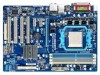
GA-M52LT-D3/GA-M52LT-S3P Motherboard Layout KB_MS ATX_12V Socket AM3 COAXIAL LPT COMA R_USB USB_LAN CPU_FAN AUDIO F_AUDIO GA-M52LT-D3/GA-M52LT-S3P PCIEX16 SPDIF_O Realtek RTL8201EL PCIEX1_1 PCIEX1_2 BAT CODEC PCI1 CLR_CMOS NVIDIA® nForce 520LE CD_IN PCI2 SPDIF_I PCI3 iTE - Gigabyte GA-M52LT-D3 | Manual - Page 8
GA-M52LT-D3/GA-M52LT-S3P Motherboard Block Diagram AM3 CPU CPU CLK+/- (200 MHz) DDR3 1666(O.C.)/1333/1066 MHz Dual Channel Memory PCIe CLK (100 MHz) 1 PCI Express x16 Hyper Transport PCI Express Bus x1 x1 PCIe CLK (100 MHz) 2 PCI Express x1 2 SATA 3Gb/s NVIDIA® nForce 520LE Realtek RTL8201EL - Gigabyte GA-M52LT-D3 | Manual - Page 9
's manual and follow these procedures: • Prior to installation, do not remove or break motherboard S/N wrist strap when handling electronic com- ponents such as a motherboard, CPU or memory. If you do not have an ESD wrist steps or have a problem related to the use of the product, please consult - Gigabyte GA-M52LT-D3 | Manual - Page 10
Bus Support for AM3 processors: AMD Phenom™ II processor/ AMD Athlon™ II processor (Go to GIGABYTE's website for the latest CPU support list.) 2000 MT/s Chipset NVIDIA® nForce 520LE Memory Audio 4 x 1.5V DDR3 DIMM sockets supporting up to - Gigabyte GA-M52LT-D3 | Manual - Page 11
warning CPU/System fan speed control (Note 2) 2 x 8 Mbit flash Use of licensed AWARD BIOS Support for DualBIOS™ PnP 1.0a, DMI 2.0, SM BIOS 2.4, ACPI 1.0b Support for @BIOS Support for Q-Flash Support for Xpress BIOS Rescue Support for Download Center Support for Xpress Install Support for Xpress - Gigabyte GA-M52LT-D3 | Manual - Page 12
before you begin to install the CPU: • Make sure that the motherboard supports the CPU. (Go to GIGABYTE's website for the latest CPU support list.) • Always turn off the computer and unplug the power cord from the power outlet before installing the CPU to prevent hardware damage. • Locate the - Gigabyte GA-M52LT-D3 | Manual - Page 13
below to correctly install the CPU into the motherboard CPU socket. • Before installing the CPU, make sure to turn off the computer and unplug the power cord from the power outlet to prevent damage to the CPU. • Do not force the CPU into the CPU socket. The CPU cannot fit in if oriented incorrectly - Gigabyte GA-M52LT-D3 | Manual - Page 14
lock into place. (Refer to your CPU cooler installation manual for instructions on installing the cooler.) Step 5: Finally, attach the power connector of the CPU cooler to the CPU fan header (CPU_FAN) on the motherboard. Use extreme care when removing the CPU cooler because the thermal grease/tape - Gigabyte GA-M52LT-D3 | Manual - Page 15
This motherboard provides four DDR3 memory sockets and supports Dual Channel Technology. After the memory is installed, the BIOS will that you install them in the DDR3_1 and DDR3_2 sockets. DDR3_1 DDR3_2 DDR3_3 DDR3_4 Due to CPU limitation, read the following guidelines before installing the memory - Gigabyte GA-M52LT-D3 | Manual - Page 16
to each other or DDR DIMMs. Be sure to install DDR3 DIMMs on this motherboard. Notch DDR3 DIMM A DDR3 memory module has a notch, so it can only Spread the retaining clips at both ends of the memory socket. Place the memory module on the socket. As indicated in the picture on the left, place - Gigabyte GA-M52LT-D3 | Manual - Page 17
an expansion card: • Make sure the motherboard supports the expansion card. Carefully read the manual that came with your expansion card. • Always If necessary, go to BIOS Setup to make any required BIOS changes for your expansion card(s). 7. Install the driver provided with the expansion card - Gigabyte GA-M52LT-D3 | Manual - Page 18
as a mouse, modem or other peripherals. USB 2.0/1.1 Port The USB port supports the USB 2.0/1.1 specification. Use this port for USB devices such as a , first remove the cable from your device and then remove it from the motherboard. • When removing the cable, pull it straight out from the connector. - Gigabyte GA-M52LT-D3 | Manual - Page 19
to perform different functions via the audio software. Only microphones still MUST be connected to the default Mic in jack ( ). Refer to the instructions on setting up a 2/4/5.1/7.1-channel audio configuration in Chapter 5, "Configuring 2/4/5.1/7.1-Channel Audio." - 19 - Hardware Installation - Gigabyte GA-M52LT-D3 | Manual - Page 20
devices. • After installing the device and before turning on the computer, make sure the device cable has been securely attached to the connector on the motherboard. Hardware Installation - 20 - - Gigabyte GA-M52LT-D3 | Manual - Page 21
supply can supply enough stable power to all the components on the motherboard. Before connecting the power connector, first make sure the power supply is the correct orientation. The 12V power connector mainly supplies power to the CPU. If the 12V power connector is not connected, the computer will - Gigabyte GA-M52LT-D3 | Manual - Page 22
wire is the ground wire). The motherboard supports CPU fan speed control, which requires the use of a CPU fan with fan speed control design. floppy disk drive. The types of floppy disk drives supported are: 360 KB, 720 KB, 1.2 MB, 1.44 MB, and 2.88 MB. Before connecting a floppy disk drive, be sure - Gigabyte GA-M52LT-D3 | Manual - Page 23
and are compatible with SATA 1.5Gb/s standard. Each SATA connector supports a single SATA device. The NVIDIA® nForce 520LE controller supports RAID 0 and RAID 1. Refer to Chapter 5, "Configuring SATA Hard Drive(s)," for instructions on configur- ing a RAID array. Pin No. Definition 1 GND 2 TXP - Gigabyte GA-M52LT-D3 | Manual - Page 24
a beep code. One single short beep will be heard if no problem is detected at system startup. If a problem is detected, the BIOS may issue beeps in different patterns to indicate the problem. Refer to Chapter 5, "Troubleshooting," for information about beep codes. • HD (Hard Drive Activity LED, Blue - Gigabyte GA-M52LT-D3 | Manual - Page 25
pin assignments of the motherboard header. Incorrect connection between the module connector and the motherboard header will make the device front panel audio header supports HD audio by default. If your chassis provides an AC'97 front panel audio module, refer to the instructions on how to activate - Gigabyte GA-M52LT-D3 | Manual - Page 26
This header supports digital S/PDIF Out and connects a S/PDIF digital audio cable (provided by expansion cards) for digital audio output from your motherboard to certain expansion digital audio cable, carefully read the manual for your expansion card. 1 Pin No. Definition 1 SPDIFO 2 GND Hardware - Gigabyte GA-M52LT-D3 | Manual - Page 27
the jumper. Failure to do so may cause damage to the motherboard. • After system restart, go to BIOS Setup to load factory defaults (select Load Optimized Defaults) or manually configure the BIOS settings (refer to Chapter 2, "BIOS Setup," for BIOS configurations). - 27 - Hardware Installation - Gigabyte GA-M52LT-D3 | Manual - Page 28
16) BAT (Battery) The battery provides power to keep the values (such as BIOS configurations, date, and time information) in the CMOS when the computer is turned off. Replace the battery when the battery voltage drops to a low level, - Gigabyte GA-M52LT-D3 | Manual - Page 29
that searches and downloads the latest version of BIOS from the Internet and updates the BIOS. For instructions on using the Q-Flash and @BIOS utilities, refer to Chapter 4, "BIOS Update Utilities." • Because BIOS flashing is potentially risky, if you do not encounter problems using the current - Gigabyte GA-M52LT-D3 | Manual - Page 30
v6.00PG, An Energy Star Ally Copyright (C) 1984-2010, Award Software, Inc. Motherboard Model BIOS Version GA-M52LT-D3 E3 . . . . : BIOS Setup : XpressRecovery2 : Boot Menu : Qflash 05/10/2010-NF-520LE-6A61KG0LC-00 Function Keys Function Keys Function Keys: : POST SCREEN - Gigabyte GA-M52LT-D3 | Manual - Page 31
BIOS Version: GA-M52LT-D3, E3) CMOS Setup Utility-Copyright (C) 1984-2010 Award Software MB Intelligent Tweaker(M.I.T.) Standard CMOS Features Advanced BIOS Select Item F10: Save & Exit Setup Change CPU's Clock & Voltage BIOS Setup Program Function Keys Move the selection bar - Gigabyte GA-M52LT-D3 | Manual - Page 32
MB Intelligent Tweaker(M.I.T.) Use this menu to configure the clock, frequency and voltages of your CPU, memory, etc. Standard CMOS system boot, etc. Advanced BIOS Features Use this menu to configure the device boot order, advanced features available on the CPU, and the primary display adapter. - Gigabyte GA-M52LT-D3 | Manual - Page 33
the North Bridge controller frequency for the installed CPU. The adjustable range is dependent on the CPU being used. Set Memory Clock Determines whether to manually set the memory clock. Auto lets BIOS automatically set the memory clock as required. Manual allows the memory clock control item below - Gigabyte GA-M52LT-D3 | Manual - Page 34
to two single-channel. (Default) DDR3 Timing Items Manual allows all DDR3 Timing items below to be configurable. Options are: Auto (default), Manual. CAS# latency Options are: Auto (default), 4T~ , 2T. (Note) This item appears only if you install a CPU that supports this feature. BIOS Setup - 34 - - Gigabyte GA-M52LT-D3 | Manual - Page 35
the CPU voltage as required. The adjustable range is dependent on the CPU being installed. (Default: Normal) Note: Increasing CPU voltage may result in damage to your CPU or reduce the useful life of the CPU. Normal CPU Vcore Displays the normal operating voltage of your CPU. - 35 - BIOS Setup - Gigabyte GA-M52LT-D3 | Manual - Page 36
None] [None] [None] [None] Drive A Floppy 3 Mode Support Halt On Base Memory Extended Memory [1.44M, 3.5"] [Disabled] [All, devices by using one of the two methods below: • Auto Lets the BIOS automatically detect IDE/SATA devices during the POST. (Default) • None If - Gigabyte GA-M52LT-D3 | Manual - Page 37
to enter the parameters manually, refer to the information 25", 720K/3.5", 1.44M/3.5", 2.88M/3.5". Floppy 3 Mode Support Allows you to specify whether the installed floppy disk drive for an error during the POST. All Errors Whenever the BIOS detects a non-fatal error the system boot will stop. - Gigabyte GA-M52LT-D3 | Manual - Page 38
Manual Allows you to individually enable/disable CPU Core 2 and Core 3. CPU core 2 (Note) Enables or disables CPU Core 2. (Default: Enabled) CPU core 3 (Note) Enables or disables CPU Core 3. (Default: Enabled) (Note) This item is present only if you install a CPU that supports this feature. BIOS - Gigabyte GA-M52LT-D3 | Manual - Page 39
Show Allows you to determine whether to display the GIGABYTE Logo at system startup. Disabled displays normal POST message. (Default: Enabled) Backup BIOS Image to HDD Allows the system to copy the BIOS image file to the hard drive. If the system BIOS is corrupted, it will be recovered from this - Gigabyte GA-M52LT-D3 | Manual - Page 40
channel of the integrated SATA 3Gb/s controller. This item is configurable only if the NV SATA RAID function item is set to Enabled. (Default: Enabled) BIOS Setup - 40 - - Gigabyte GA-M52LT-D3 | Manual - Page 41
: Enabled) USB Storage Function Determines whether to detect USB storage devices, including USB flash drives and USB hard drives during the POST. (Default: Enabled) - 41 - BIOS Setup - Gigabyte GA-M52LT-D3 | Manual - Page 42
:ss) Alarm HPET Support (Note) HPET Mode (Note) Power On By Keyboard x KB Power ON Password AC Back Function ErP Support [S3(STR)] [Instant-Off] [Enabled] [Enabled] by a wake-up signal from a modem that supports wake-up function. (Default: Enabled) USB Resume from - Gigabyte GA-M52LT-D3 | Manual - Page 43
may not be effective. HPET Support (Note) Enables or disables High This item is configurable only if the HPET Support is set to Enabled. (Default: 32 the return of the AC power. ErP Support Determines whether to let the system consume less Supported on Windows 7/Vista operating system only. - 43 - Gigabyte GA-M52LT-D3 | Manual - Page 44
Assignment Auto 3,4,5,7,9,10,11,12,14,15 PCI 3 IRQ Assignment Auto 3,4,5,7,9,10,11,12,14,15 PCI 4 IRQ Assignment Auto 3,4,5,7,9,10,11,12,14,15 BIOS auto-assigns IRQ to the first PCI slot. (Default) Assigns IRQ 3,4,5,7,9,10,11,12,14,15 to the first PCI slot - Gigabyte GA-M52LT-D3 | Manual - Page 45
to the motherboard CI header CPU Temperature Displays current system/CPU temperature. Current CPU/SYSTEM FAN Speed (RPM) Displays current CPU/system fan speed. System/CPU Warning Temperature Sets the warning threshold for system/CPU temperature. When system/CPU temperature exceeds the threshold, BIOS - Gigabyte GA-M52LT-D3 | Manual - Page 46
FAN Control is set to Enabled. Auto Lets the BIOS automatically detect the type of CPU fan installed and sets the optimal CPU fan control mode. (Default) Voltage Sets Voltage mode for a 3-pin CPU fan. PWM Sets PWM mode for a 4-pin CPU fan. System Smart FAN Control Enables or disables the - Gigabyte GA-M52LT-D3 | Manual - Page 47
BIOS settings for the motherboard. 2-11 Load Optimized Defaults CMOS Setup Utility-Copyright (C) 1984-2010 Award Software MB optimal BIOS default settings. The BIOS defaults settings help the system to operate in optimum state. Always load the Optimized defaults after updating the BIOS or - Gigabyte GA-M52LT-D3 | Manual - Page 48
2-12 Set Supervisor/User Password CMOS Setup Utility-Copyright (C) 1984-2010 Award Software MB Intelligent Tweaker(M.I.T.) Standard CMOS Features Advanced BIOS Features Integrated Peripherals Power Management Setup PnP/PCI Configurations Enter Password: PC Health Status Load Fail - Gigabyte GA-M52LT-D3 | Manual - Page 49
Save & Exit Setup CMOS Setup Utility-Copyright (C) 1984-2010 Award Software MB Intelligent Tweaker(M.I.T.) Load Fail-Safe Defaults Standard CMOS Features Load Optimized Defaults Advanced BIOS Features Integrated Peripherals Save to CMOS and E XI T (Y/NS)e?tYSupervisor Password - Gigabyte GA-M52LT-D3 | Manual - Page 50
BIOS Setup - 50 - - Gigabyte GA-M52LT-D3 | Manual - Page 51
recommended drivers. Or click Install Single Items to manually select the drivers instructions to restart your system. You can install other applications included in the motherboard driver disk. • For USB 2.0 driver support under the Windows XP operating system, please install the Windows XP Service - Gigabyte GA-M52LT-D3 | Manual - Page 52
applications that GIGABYTE develops and some free software. You can click the Install button on the right of an item to install it. 3-3 Technical Manuals This page provides GIGABYTE's application guides, content descriptions for this driver disk, and the motherboard manuals. Drivers Installation - Gigabyte GA-M52LT-D3 | Manual - Page 53
3-4 Contact For the detailed contact information of the GIGABYTE Taiwan headquarter or worldwide branch offices, click the URL on this page to link to the GIGABYTE website. 3-5 System This page provides the basic system information. - 53 - Drivers Installation - Gigabyte GA-M52LT-D3 | Manual - Page 54
Center To update the BIOS, drivers, or applications, click the Download Center button to link to the GIGABYTE website. The latest version of the BIOS, drivers, or applications will be displayed. 3-7 New Utilities This page provides a quick link to GIGABYTE's lately developed utilities for users - Gigabyte GA-M52LT-D3 | Manual - Page 55
up your system soon after the operating system and drivers are installed. • The amount of data and hard to restore it. System Requirements: • At least 512 MB of system memory • VESA compatible graphics card • Windows are not supported. • Hard drives in RAID/AHCI mode are not supported. Installation and - Gigabyte GA-M52LT-D3 | Manual - Page 56
note that if there is no enough unallocated space, Xpress Recovery2 cannot save the backup file. B. Accessing Xpress Recovery2 1. Boot from the motherboard driver disk to access Xpress Recovery2 for the first time. When you see the following message: Press any key to startup Xpress Recovery2, press - Gigabyte GA-M52LT-D3 | Manual - Page 57
D. Using the Restore Function in Xpress Recovery2 Select RESTORE to restore the backup to your hard drive in case the system breaks down. The RESTORE option will not be present if no backup is created before. E. Removing the Backup Step 1: If you wish to remove the backup file, select REMOVE. Step - Gigabyte GA-M52LT-D3 | Manual - Page 58
, if the BIOS update file is saved to a hard drive in RAID/AHCI mode or a hard drive attached to an independent IDE/SATA controller, use the key during the POST to access Q-Flash. Award Modular BIOS v6.00PG, An Energy Star Ally Copyright (C) 1984-2010, Award Software, Inc. GA-M52LT-D3 E3 - Gigabyte GA-M52LT-D3 | Manual - Page 59
key to select Update BIOS from Drive and press . • The Save Main BIOS to Drive option allows you to save the current BIOS file. • Q-Flash only supports USB flash drive or hard drives using FAT32/16/12 file system. • If the BIOS update file is saved to a hard drive in RAID/AHCI mode or a hard - Gigabyte GA-M52LT-D3 | Manual - Page 60
defaults. System will re-detect all peripheral devices after a BIOS update, so we recommend that you reload BIOS defaults. CMOS Setup Utility-Copyright (C) 1984-2010 Award Software MB Intelligent Tweaker(M.I.T.) Load Fail-Safe Defaults Standard CMOS Features Load Optimized Defaults - Gigabyte GA-M52LT-D3 | Manual - Page 61
. If the BIOS update file for your motherboard is not present on the @BIOS server site, please manually download the BIOS update file from GIGABYTE's website and follow the instructions in "Update the BIOS without Using the Internet Update Function" below. 2. Update the BIOS without Using the - Gigabyte GA-M52LT-D3 | Manual - Page 62
cores that can be enabled/disabled depends on the CPU being used. Available functions in EasyTune 6 may differ by motherboard model. Grayed-out area(s) indicates that the item is not configurable or the function is not supported. Incorrectly doing overclock/overvoltage may result in damage to the - Gigabyte GA-M52LT-D3 | Manual - Page 63
your Bluetooth cell phone, click Refresh to let Auto Green re-detect the device.) Before creating a Bluetooth cell phone key, make sure your motherboard has a Bluetooth receiver and you have turned on the search and Bluetooth functions on your phone. Configuring the Bluetooth cell phone key: After - Gigabyte GA-M52LT-D3 | Manual - Page 64
Unique Features - 64 - - Gigabyte GA-M52LT-D3 | Manual - Page 65
BIOS Setup. C. Configuring RAID set in RAID BIOS. (Note) D. Make a floppy disk containing the SATA RAID driver for Windows XP. (Note) E. Install the SATA RAID driver floppy disk. • Windows Vista/XP setup disk. • Motherboard driver disk. 5-1-1 Configuring the Onboard SATA Controller A. Installing SATA - Gigabyte GA-M52LT-D3 | Manual - Page 66
Fail-Safe Defaults Figure 2 Step 2: Save changes and exit BIOS Setup. ESC: Exit F1: General Help F7: Optimized Defaults The BIOS Setup menus described in this section may differ from the exact settings for your motherboard. The actual BIOS Setup menu options you will see shall depend on the - Gigabyte GA-M52LT-D3 | Manual - Page 67
to enter the NVIDIA RAID setup utility. MediaShield ROM BIOS 6.94 Copyright (C) 2006 NVIDIA Corp. Detecting array key to select a RAID mode. The supported RAID modes include Mirroring, Striping, Stripe RAID 0 (Striping) is selected, you can manually set the stripe block size. In the Striping - Gigabyte GA-M52LT-D3 | Manual - Page 68
Step 5: Next, select the hard drives which you wish to be included in the disk array. The Free Disks block displays the information about the SATA hard drives that are available for use as RAID array drives. Press to move to the Free Disks block. Select the target hard drives using the up or - Gigabyte GA-M52LT-D3 | Manual - Page 69
utility, press in the main menu or + in the Array List screen. Now, you can proceed to the installation of the SATA controller driver and operating system. - 69 - Appendix - Gigabyte GA-M52LT-D3 | Manual - Page 70
, you also can copy the SATA controller driver from the motherboard driver disk to a USB flash drive. See the instructions below about how to copy the driver in MS-DOS and Windows mode. In MS-DOS mode: Prepare a startup disk that has CD-ROM support and a blank formatted floppy disk. Steps: 1: Boot - Gigabyte GA-M52LT-D3 | Manual - Page 71
Operating System With the SATA RAID driver diskette and correct BIOS settings, you are ready to support disk provided by an adapter manufacturer. Select the SCSI Adapter you want from the following list, or press ESC to return to the previous screen. NVIDIA RAID Driver (required) NVIDIA nForce - Gigabyte GA-M52LT-D3 | Manual - Page 72
BootDrv\UDA\WinVista folder and save the whole sataraid folder to the USB flash drive). Then use Method B to load the driver. Method A: Insert the motherboard driver disk into your system and browse to the following directory: BootDrv\UDA\WinVista\sataraid For Windows Vista 64-bit, browse to BootDrv - Gigabyte GA-M52LT-D3 | Manual - Page 73
Step 3: When a screen as shown in Figure 5 appears, select NVIDIA nForce RAID Controller and click Next. Figure 5 Step 4: After the driver is loaded, the RAID drive will appear. Select the RAID drive and then click Next to continue the OS installation (Figure 6). Figure 6 - 73 - Appendix - Gigabyte GA-M52LT-D3 | Manual - Page 74
Rebuilding an Array: Rebuilding is the process of restoring data to a hard drive from other drives in the array. Rebuilding applies only to fault-tolerant arrays such as RAID 1. To replace the old drive, make sure to use a new drive of equal or greater capacity. The procedures below assume a new - Gigabyte GA-M52LT-D3 | Manual - Page 75
audio driver. For manually configure the jack for microphone functionality. • Audio signals will be present on both of the front and back panel audio connections simultaneously. If you want to mute the back panel audio (only supported when using an HD front panel audio module), refer to instructions - Gigabyte GA-M52LT-D3 | Manual - Page 76
Step 2: Connect an audio device to an audio jack. The The current connected device is dialog box appears. Select the device according to the type of device you connect. Then click OK. Step 3: On the Speakers screen, click the Speaker Configuration tab. In the Speaker Configuration list, select - Gigabyte GA-M52LT-D3 | Manual - Page 77
S/PDIF In 1. Installing the S/PDIF In Cable: Step 1: First, attach the connector at the end of the cable to the SPDIF_IN header on your motherboard. Step 2: Secure the metal bracket to the chassis back panel with a screw. 2. Configuring S/PDIF In: On the Digital Input screen, click the Default - Gigabyte GA-M52LT-D3 | Manual - Page 78
B. S/PDIF Out The S/PDIF Out jack can transmit audio signals to an external decoder for decoding to get the best audio quality. 1. Connecting a S/PDIF Out Cable: Connect a S/PDIF coaxial cable to an external decoder for transmitting the S/PDIF digital audio signals. 2. Configuring S/PDIF Out: On the - Gigabyte GA-M52LT-D3 | Manual - Page 79
5-2-3 Configuring Microphone Recording Step 1: After installing the audio driver, the HD Audio Manager icon will appear in the notification area. Double-click the icon to access the HD Audio Manager. Step 2: Connect your microphone - Gigabyte GA-M52LT-D3 | Manual - Page 80
Step 4: To raise the recording and playback volume for the microphone, click the Microphone Boost icon on the right of the Recording Volume slider and set the Microphone Boost level. Step 5: After completing the settings above, click Start, point to All Programs, point to Accessories, and then click - Gigabyte GA-M52LT-D3 | Manual - Page 81
. Be sure to save the recorded audio file upon completion. B. Playing the Recorded Sound You can play your recording in a digital media player program that supports your audio file format. - 81 - Appendix - Gigabyte GA-M52LT-D3 | Manual - Page 82
the motherboard driver disk or download the audio driver from GIGABYTE's website to install. For more details, go to the Support&Downloads\Motherboards\FAQ page on our website and search for "onboard HD audio driver." Q: What do the beeps emitted during the POST mean? A: The following Award BIOS - Gigabyte GA-M52LT-D3 | Manual - Page 83
Procedure If you encounter any troubles during system startup, follow the troubleshooting procedure below to solve the problem. START Turn off the power. Remove all peripherals, connecting cables, and power cord etc. Make sure the motherboard does not short-circuit with the chassis or - Gigabyte GA-M52LT-D3 | Manual - Page 84
and solved. END If the procedure above is unable to solve your problem, contact the place of purchase or local dealer for help. Or go to the Support&Downloads\Technical Service Zone page to submit your question. Our customer service staff will reply you as soon as possible. Appendix - 84 - - Gigabyte GA-M52LT-D3 | Manual - Page 85
GIGABYTE. Our Commitment to Preserving the Environment In addition to high-efficiency performance, all GIGABYTE motherboards local government office, your household waste disposal service or where you purchased the product for user's manual and we will be glad to help you with your effort. - - Gigabyte GA-M52LT-D3 | Manual - Page 86
Finally, we suggest that you practice other environmentally friendly actions by understanding and using the energy-saving features of this product (where applicable), recycling the inner and outer packaging (including shipping containers) this product was delivered in, and by disposing of or - Gigabyte GA-M52LT-D3 | Manual - Page 87
- 87 - Appendix - Gigabyte GA-M52LT-D3 | Manual - Page 88
Appendix - 88 - - Gigabyte GA-M52LT-D3 | Manual - Page 89
- 89 - Appendix - Gigabyte GA-M52LT-D3 | Manual - Page 90
Appendix - 90 - - Gigabyte GA-M52LT-D3 | Manual - Page 91
- 91 - Appendix - Gigabyte GA-M52LT-D3 | Manual - Page 92
Appendix - 92 - - Gigabyte GA-M52LT-D3 | Manual - Page 93
- 93 - Appendix - Gigabyte GA-M52LT-D3 | Manual - Page 94
Appendix - 94 - - Gigabyte GA-M52LT-D3 | Manual - Page 95
231, Taiwan TEL: +886-2-8912-4000 FAX: +886-2-8912-4003 Tech. and Non-Tech. Support (Sales/Marketing) : http://ggts.gigabyte.com.tw WEB address (English): http://www.gigabyte.com WEB address (Chinese): http://www.gigabyte.tw • G.B.T. INC. - U.S.A. TEL: +1-626-854-9338 FAX: +1-626-854-9339 Tech - Gigabyte GA-M52LT-D3 | Manual - Page 96
website, select your language in the language list on the top right corner of the website. • GIGABYTE Global Service System To submit a technical or non-technical (Sales/Marketing) question, please link to: http://ggts.gigabyte.com.tw Then select your language to enter the system. Appendix - 96 -
-
 1
1 -
 2
2 -
 3
3 -
 4
4 -
 5
5 -
 6
6 -
 7
7 -
8
-
9
-
10
-
11
-
12
-
13
-
14
-
15
-
16
-
17
-
18
-
19
-
20
-
21
-
22
-
23
-
24
-
25
-
26
-
27
-
28
-
29
-
30
-
31
-
32
-
33
-
34
-
35
-
36
-
37
-
38
-
39
-
40
-
41
-
42
-
43
-
44
-
45
-
46
-
47
-
48
-
49
-
50
-
51
-
52
-
53
-
54
-
55
-
56
-
57
-
58
-
59
-
60
-
61
-
62
-
63
-
64
-
65
-
66
-
67
-
68
-
69
-
70
-
71
-
72
-
73
-
74
-
75
-
76
-
77
-
78
-
79
-
80
-
81
-
82
-
83
-
84
-
85
-
86
-
87
-
88
-
89
-
90
-
91
-
92
-
93
-
94
-
95
-
96
 |
 |

GA-M52LT-D3/
GA-M52LT-S3P
AM3 socket motherboard for
AMD Phenom
™
II processor/AMD Athlon
™
II processor
User's Manual
Rev. 2301
12ME-M52LTD3-2301R