Gigabyte GA-M55S-S3 Manual
Gigabyte GA-M55S-S3 Manual
 |
View all Gigabyte GA-M55S-S3 manuals
Add to My Manuals
Save this manual to your list of manuals |
Gigabyte GA-M55S-S3 manual content summary:
- Gigabyte GA-M55S-S3 | Manual - Page 1
GA-M55S-S3 (rev. 2.0) AMD Socket AM2 Processor Motherboard User's Manual Rev. 2002 12ME-M55S3R-2002R * The WEEE marking on the product indicates this product must not be disposed of with user's other household waste and must - Gigabyte GA-M55S-S3 | Manual - Page 2
Motherboard GA-M55S-S3 (rev. 2.0) Nov. 10, 2006 Motherboard GA-M55S-S3 (rev. 2.0) Nov. 10, 2006 - Gigabyte GA-M55S-S3 | Manual - Page 3
product information and specifications, please carefully read the "Product User Manual". „ For detailed information related to Gigabyte's unique features, please go to "Technology Guide" section on Gigabyte's website to read or download the information you need. For more product details, please - Gigabyte GA-M55S-S3 | Manual - Page 4
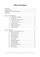
Table of Contents ItemChecklist ...6 OptionalAccessories ...6 GA-M55S-S3 (rev. 2.0) Motherboard Layout 7 Block Diagram ...8 Chapter 1 Hardware Installation 9 1-1 Considerations Prior to Installation 9 1-2 Feature Summary 10 1-3 Installation of the CPU and CPU Cooler 12 1-3-1 Installation of the - Gigabyte GA-M55S-S3 | Manual - Page 5
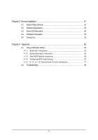
4 Appendix 55 4-1 Unique Software Utilities 55 4-1-1 EasyTune 5 Introduction 55 4-1-2 Xpress Recovery2 Introduction 56 4-1-3 Flash BIOS Method Introduction 58 4-1-4 Configuring SATA Hard Drive(s 67 4-1-5 2- / 4- / 6- / 8- Channel Audio Function Introduction 77 4-2 Troubleshooting 82 - 5 - - Gigabyte GA-M55S-S3 | Manual - Page 6
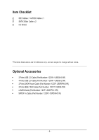
Item Checklist IDE Cable x 1 & FDD Cable x 1 SATA 3Gb/s Cable x 2 I/O Shield * The items listed above are for reference only, and are subject to change without notice. Optional Accessories Š 2 Ports USB 2.0 Cable (Part Number: 12CR1-1UB030-51/R) Š 4 Ports USB 2.0 Cable ( - Gigabyte GA-M55S-S3 | Manual - Page 7
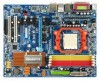
GA-M55S-S3 (rev. 2.0) Motherboard Layout CPU_FAN KB_MS ATX_12V ATX SPDIF_O SPDIFO_OPT Socket AM2 COMA LPT PWR_FAN USB 1394 USB LAN1 Marvell 88E1116 AUDIO PCIE_12V F_AUDIO PCIE_1 CODEC PCIE_16_1 PCIE_2 SPDIF_I CD_IN PCIE_3 PCIE_4 PCI1 IT8716 PCI2 REV: 2.0 FDD DDRII_1 DDRII_2 - Gigabyte GA-M55S-S3 | Manual - Page 8
100 MHz) AMD Socket AM2 CPU CPUCLK+/-(200 MHz) DDRII 800/667/533 MHz DIMM Hyper Transport Bus Dual Channel Memory LAN PCI Express x16 PCI-ECLK (100 MHz) PCI Express Bus x1 x1 x1 x1 nVIDIA® nForce 550 4 PCI Express x1 PCI Bus TSB43AB23 CODEC RJ45 Marvell 88E1116 BIOS 4 SATA 3Gb/s ATA33 - Gigabyte GA-M55S-S3 | Manual - Page 9
instructions below: 1. Please turn off the computer and unplug its power cord. 2. When handling the motherboard , avoid touching any metal leads or connectors. 3. It is best to wear an electrostatic discharge (ESD) cuff when handling electronic components (CPU motherboard problem manual - Gigabyte GA-M55S-S3 | Manual - Page 10
front audio connector Š 1 CD In connector Š 1 S/PDIF In connector Š 3 USB 2.0/1.1 connectors for additional 6 USB 2.0/1.1 ports by cables Š 2 IEEE 1394a connectors for additional 2 ports by cables Š 1 Chassis Intrusion connector Š 1 power LED connector GA-M55S-S3 (rev. 2.0) Motherboard - 10 - Gigabyte GA-M55S-S3 | Manual - Page 11
Š Supports CPU Smart Fan function(Note 2) BIOS Š 1 4Mbit flash ROM Š Use of licensed AWARD BIOS Additional Features Š Supports @BIOS Š Supports Download Center Š Supports Q-Flash Š Supports EasyTune(Note 3) Š Supports Xpress Install Š Supports Xpress Recovery2 Š Supports Xpress BIOS Rescue - Gigabyte GA-M55S-S3 | Manual - Page 12
on the middle of the CPU and gently press the metal lever back into its original position. Please use extra care when installing the CPU. The CPU will not fit if positioned incorrectly. Rather than applying force, please change the positioning of the CPU. GA-M55S-S3 (rev. 2.0) Motherboard - 12 - - Gigabyte GA-M55S-S3 | Manual - Page 13
paste on the surface of the CPU. Install all the CPU cooler components (Please refer to the cooler manual for detailed installation instructions). Fig.2 Please connect the CPU cooler power connector to the CPU_FAN connector located on the motherboard so that the CPU cooler can properly function to - Gigabyte GA-M55S-S3 | Manual - Page 14
are unable to insert the module, please switch the direction. The motherboard supports DDRII memory modules, whereby BIOS will automatically detect memory capacity and specifications. Memory modules are designed so when you wish to remove the DIMM module. GA-M55S-S3 (rev. 2.0) Motherboard - 14 - - Gigabyte GA-M55S-S3 | Manual - Page 15
English Dual Channel Memory Configuration The GA-M55S-S3 supports the Dual Channel Technology. After operating the Dual Channel Technology, the bandwidth of Memory Bus will double. Due to CPU limitation, if you wish to operate the Dual Channel Technology, follow the guidelines below: 1. Dual - Gigabyte GA-M55S-S3 | Manual - Page 16
outlined below: 1. Read the related expansion card's instruction document before install the expansion card into the the computer, if necessary, setup BIOS utility of expansion card from BIOS. 8. Install related driver from the operating system. Installing GA-M55S-S3 (rev. 2.0) Motherboard - 16 - - Gigabyte GA-M55S-S3 | Manual - Page 17
port is capable of providing digital audio to external speakers or compressed AC3 support USB controller, please contact OS vendor for possible patch or driver upgrade. For more information please contact your OS or device(s) vendors. LAN Port The provided Internet connection is Gigabit Ethernet - Gigabyte GA-M55S-S3 | Manual - Page 18
channel audio setup steps for detailed software configuration information. 1-7 Connectors Introduction 3 14 6 2 8 13 15 14 7 1) ATX_12V 2) ATX (Power Connector) 3) PCIE_12V 4) CPU_FAN 5) SYS_FAN 6) PWR_FAN 7) FDD 8) IDE1 9) SATAII1 / 2 / 3 / 4 10) BATTERY GA-M55S-S3 (rev. 2.0) Motherboard - Gigabyte GA-M55S-S3 | Manual - Page 19
all components and devices are properly installed. Align the power connector with its proper location on the motherboard and connect tightly. The ATX_12V power connector mainly supplies power to the CPU. If the ATX_12V power connector is not connected, the system will not start. Caution! Please use - Gigabyte GA-M55S-S3 | Manual - Page 20
color-coded power connector CPU damage or system hanging caused by overheating. 1 CPU_FAN 1 SYS_FAN 1 PWR_FAN CPU_FAN : Pin No. 1 2 3 4 Definition GND +12V / Speed Control Sense Speed Control SYS_FAN / PWR_FAN : Pin No. Definition 1 GND 2 +12V 3 Sense GA-M55S-S3 (rev. 2.0) Motherboard - Gigabyte GA-M55S-S3 | Manual - Page 21
end of the cable connects to the FDD drive. The types of FDD drives supported are: 360KB, 720KB, 1.2MB, 1.44MB and 2.88MB. Before attaching the the other as Slave (for information on settings, please refer to the instructions located on the IDE device). Before attaching the IDE cable, please take note - Gigabyte GA-M55S-S3 | Manual - Page 22
300MB/s transfer rate. Please refer to the BIOS setting for the SATA 3Gb/s and install the proper driver in order to work properly. SATAII4 Pin No . Dispose of used batteries according to the manufacturer's instructions. If you want to erase CMOS... 1. Turn GA-M55S-S3 (rev. 2.0) Motherboard - 22 - - Gigabyte GA-M55S-S3 | Manual - Page 23
English 11) F_PANEL (Front Panel Jumper) Please connect the power LED, PC speaker, reset switch and power switch etc. of your chassis front panel to the F_PANEL connector according to the pin assignment below. Message LED/ Power/ Sleep LED Power Switch Speaker Connector MSG+ MSG- PW+ PWSPEAK+ - Gigabyte GA-M55S-S3 | Manual - Page 24
(R) 6 NC 7 NC 8 No Pin 9 Line Out (L) 10 NC By default, the audio driver is configured to support HD Audio. To connect an AC97 front panel audio module to this connector, please refer to the instructions on page 81 about the software settings. GA-M55S-S3 (rev. 2.0) Motherboard - 24 - - Gigabyte GA-M55S-S3 | Manual - Page 25
English 14) CD_IN (CD In Connector) Connect CD-ROM or DVD-ROM audio out to the connector. Pin No. Definition 1 CD-L 2 GND 3 GND 1 4 CD-R 15) SPDIF_I (S/PDIF In Connector) Use S/PDIF IN feature only when your device has - Gigabyte GA-M55S-S3 | Manual - Page 26
1394 cable, please contact your local dealer. Pin No. Definition 2 10 1 9 1 TPA+ 2 TPA- 3 GND 4 GND 5 TPB+ 6 TPB- 7 No Pin 7 Power (12V) 8 Power (12V) 10 GND GA-M55S-S3 (rev. 2.0) Motherboard - 26 - - Gigabyte GA-M55S-S3 | Manual - Page 27
Intrusion, Case Open) This 2-pin connector allows your system to detect if the chassis cover is removed. You can check the "Case Opened" status in BIOS Setup. Pin No. Definition 1 Signal 1 2 GND 19) CLR_CMOS (Clear CMOS) You may clear the CMOS data to its default values by this header. To - Gigabyte GA-M55S-S3 | Manual - Page 28
English GA-M55S-S3 (rev. 2.0) Motherboard - 28 - - Gigabyte GA-M55S-S3 | Manual - Page 29
BIOS, either Gigabyte's Q-Flash or @BIOS utility can be used. Q-Flash allows the user to quickly and easily update or backup BIOS without entering the operating system. @BIOS is a Windows-based utility that does not require users to boot to DOS before upgrading BIOS but directly download and update - Gigabyte GA-M55S-S3 | Manual - Page 30
. F12 : Load CMOS from BIOS If your system becomes unstable and you load the default BIOS settings, you can use this function to reload the CMOS settings with a CMOS settings profile created before, without the hassles of resetting the CMOS configurations. GA-M55S-S3 (rev. 2.0) Motherboard - 30 - - Gigabyte GA-M55S-S3 | Manual - Page 31
This setup page includes all the items in standard compatible BIOS. „ Advanced BIOS Features This setup page includes all the items of speed, etc. „ MB Intelligent Tweaker(M.I.T.) This setup page is to control CPU clock and frequency ratio. „ Load Fail-Safe Defaults Fail-Safe Defaults indicates the - Gigabyte GA-M55S-S3 | Manual - Page 32
3 Mode Support Halt On Base Manual User can manually BIOS to automatically detect IDE/SATA devices during POST(default) None Select this if no IDE/SATA devices are used and the system will skip the automatic detection step and allow for faster system start up. GA-M55S-S3 (rev. 2.0) Motherboard - Gigabyte GA-M55S-S3 | Manual - Page 33
2.88M byte capacity. Floppy 3 Mode Support (for Japan Area) Disabled Normal Floppy All Errors Whenever the BIOS detects a non-fatal the BIOS. Base Memory The POST of the BIOS motherboard, or 640K for systems with 640K or more memory installed on the motherboard. Extended Memory The BIOS - Gigabyte GA-M55S-S3 | Manual - Page 34
list BIOS can not tell from 720K, 1.2M or 1.44M drive type as they are all 80 tracks. Disabled BIOS will not search for the type of floppy disk drive by track number. Note that there will not be any warning message if the drive installed is 360K. (Default value) GA-M55S-S3 (rev. 2.0) Motherboard - Gigabyte GA-M55S-S3 | Manual - Page 35
Disabled Enabled Disable this function. (Default value) Enable Away Mode in Windows XP Media Center operating system. (Away Mode: Enables the system to you install a PCI card and a PCI Express VGA card on the motherboard. PCI Slot PEG Set Init Display First to PCI VGA card. Set Init Display First - Gigabyte GA-M55S-S3 | Manual - Page 36
USB Keyboard Support USB Mouse Support Legacy USB storage detect [Press Enter] [Enabled] [Auto] [All Enabled] [Enabled] [Auto] [Press Enter] [Enabled] [Disabled] [3F8/IRQ4] [378/IRQ7] [SPP] 3 [V1.1+V2.0] [Disabled this channel. It will operate in ATA mode. GA-M55S-S3 (rev. 2.0) Motherboard - 36 - - Gigabyte GA-M55S-S3 | Manual - Page 37
Audio Function Auto Auto-detect onboard audio function. (Default value) Disabled Disable this function. SMART LAN CMOS Setup Utility-Copyright (C) 1984-2006 Award Software SMART LAN This motherboard incorporates cable diagnostic feature designed to detect the status of the attached LAN cable. - Gigabyte GA-M55S-S3 | Manual - Page 38
the approximate length of the attached LAN cable. When a Cable Problem Occurs... If a cable problem occurs on a specified pair of LAN chip. Enabled Enable this function. Disabled Disable this function. (Default value) Onboard Serial Port 1 Auto BIOS GA-M55S-S3 (rev. 2.0) Motherboard - 38 - - Gigabyte GA-M55S-S3 | Manual - Page 39
Use DMA to 1. On-Chip USB V1.1+V2.0 V1.1 Disabled Enable USB 1.1 and USB 2.0 controllers. (Default value) Enable only USB 1.1 controller Disable onchip USB support. USB Keyboard Support Enabled Enable USB keyboard support. Disabled Disable USB keyboard support. (Default value) USB Mouse - Gigabyte GA-M55S-S3 | Manual - Page 40
(POS) Set ACPI suspend type to S1/POS(Power On Suspend). (Default value) S3(STR) Set ACPI suspend type to S3/STR(Suspend To RAM). Soft-Off by Power button Instant-Off Press power button then , 1~31 Time (hh: mm: ss) Alarm : (0~23) : (0~59) : (0~59) GA-M55S-S3 (rev. 2.0) Motherboard - 40 - - Gigabyte GA-M55S-S3 | Manual - Page 41
, the system will be in "Off" state. (Default value) Full-On When AC-power back to the system, the system always in "On" state. - 41 - BIOS Setup - Gigabyte GA-M55S-S3 | Manual - Page 42
) Set IRQ 3,4,5,7,9,10,11,12,14,15 to PCI 2. Auto assign IRQ to PCI 1. (Default value) Set IRQ 3,4,5,7,9,10,11,12,14,15 to PCI 1. GA-M55S-S3 (rev. 2.0) Motherboard - 42 - - Gigabyte GA-M55S-S3 | Manual - Page 43
. 90oC / 194oF Disabled Monitor CPU temperature at 90oC / 194oF. Disable this function. (Default value) CPU/POWER/SYSTEM FAN Fail Warning Disabled Disable CPU/Power/System fan fail warning function. (Default value) Enabled Enable CPU/Power/System fan fail warning function. - 43 - BIOS Setup - Gigabyte GA-M55S-S3 | Manual - Page 44
Value) Voltage Set to Voltage when you use a CPU fan with a 3-pin fan power cable. PWM Set to PWM when you use a CPU fan with a 4-pin fan power cable. (Note) Whether the CPU Smart FAN Control function is supported will depend on the CPU you install. GA-M55S-S3 (rev. 2.0) Motherboard - 44 - - Gigabyte GA-M55S-S3 | Manual - Page 45
Incorrectly using these features may result in system instability or corruption. Doing a overclock or overvoltage on CPU, chipsets and memory modules may result in damages or shortened life expectancy to these value) +0.025V ~ +0.375V Increase HT-Link voltage by 0.025V~0.375V. - 45 - BIOS Setup - Gigabyte GA-M55S-S3 | Manual - Page 46
overclocking your system through the increase of the CPU voltage, damage to the CPU or decrease in the CPU life expectancy may occur. Supports adjustable CPU Voltage from 0.8000V to 1.5500V. (Default value: Normal) Normal CPU Vcore Display your CPU Vcore Voltage. GA-M55S-S3 (rev. 2.0) Motherboard - Gigabyte GA-M55S-S3 | Manual - Page 47
Select Item F10: Save & Exit Setup F11: Save CMOS to BIOS F12: Load CMOS from BIOS Load Fail-Safe Defaults Fail-Safe defaults contain the most appropriate Standard CMOS Features Load Fail-Safe Defaults Advanced BIOS Features Load Optimized Defaults Integrated Peripherals Set Supervisor - Gigabyte GA-M55S-S3 | Manual - Page 48
BIOS Features Menu, you will be prompted for the password every time the system is rebooted or any time you try to enter Setup Menu. If you select "Setup" at "Password Check" in Advance BIOS Features Menu, you will be prompted only when you try to enter Setup. GA-M55S-S3 (rev. 2.0) Motherboard - Gigabyte GA-M55S-S3 | Manual - Page 49
Health Status Exit Without Saving MB Intelligent Tweaker(M.I.T.) Esc: Quit F8: Q-Flash : Select Item F10: Save & Exit Setup F11: Save CMOS to BIOS F12: Load CMOS from BIOS Save Data to CMOS Type "Y" will quit the Setup Utility and save the user setup value to RTC CMOS. Type "N" will return to - Gigabyte GA-M55S-S3 | Manual - Page 50
English GA-M55S-S3 (rev. 2.0) Motherboard - 50 - - Gigabyte GA-M55S-S3 | Manual - Page 51
will continue to install other drivers. System will reboot automatically after install the drivers, afterward you can install others application. For USB2.0 driver support under Windows XP operating system, please use Windows Service Pack. After install Windows Service Pack, it will show a question - Gigabyte GA-M55S-S3 | Manual - Page 52
This page displays all the tools that Gigabyte developed and some free software, you can choose anyone you want and press "install" to install them. 3-3 Driver CD Information This page lists the contents of software and drivers in this CD-title. GA-M55S-S3 (rev. 2.0) Motherboard - 52 - - Gigabyte GA-M55S-S3 | Manual - Page 53
English 3-4 Hardware Information This page lists all device you have for this motherboard. 3-5 Contact Us Please see the last page for details. - 53 - Drivers Installation - Gigabyte GA-M55S-S3 | Manual - Page 54
English GA-M55S-S3 (rev. 2.0) Motherboard - 54 - - Gigabyte GA-M55S-S3 | Manual - Page 55
model support these Unique Software Utilities, please check your MB features.) 4-1-1 EasyTune 5 Introduction EasyTune 5 presents the most convenient Windows based system performance enhancement and manageability utility. Featuring several powerful yet easy to use tools such as 1) Overclocking for - Gigabyte GA-M55S-S3 | Manual - Page 56
of hard disk data. Supporting Microsoft operating systems including Windows XP/2000/NT/98/Me Modular BIOS v6.00PG, An Energy Star Ally Copyright (C) 1984-2006, Award Software, Inc. M55S-S3 FAa . . . . :BIOS Setup/Q- drivers as well as software. GA-M55S-S3 (rev. 2.0) Motherboard - 56 - - Gigabyte GA-M55S-S3 | Manual - Page 57
Windows 2000, be sure to execute the EnableBigLba.exe program from the driver CD before data backup. 2. It is normal that data backup takes longer time than data restoration. 3. Xpress Recovery2 is compliant with the GPL regulations. 4. On a few motherboards based on Nvidia chipsets, BIOS update - Gigabyte GA-M55S-S3 | Manual - Page 58
Primary Master : FUJITSU MPE3170AT ED-03-08 Primary Slave : None Secondary Master : CREATIVEDVD-RM DVD1242E BC101 Secondary Slave : None Press DEL to enter SETUP / Dual BIOS / Q-Flash / F9 For Xpress Recovery 08/07/2003-i875P-6A79BG03C-00 GA-M55S-S3 (rev. 2.0) Motherboard - 58 - - Gigabyte GA-M55S-S3 | Manual - Page 59
Backup Load Default Settings Save Settings to CMOS Q-Flash Utility Load Main BIOS from Floppy Load Backup BIOS from Floppy Save Main BIOS to Floppy Save Backup BIOS to Floppy Enter : Run :Move ESC:Reset F10:Power Off Dual BIOS utility bar Q-FlashTM utility title bar Action bar Task menu for - Gigabyte GA-M55S-S3 | Manual - Page 60
Main BIOS to Floppy Save Backup BIOS to Floppy Enter : Run :Move ESC:Reset F10:Power Off Do not turn off power or reset your system at this stage!! After BIOS file is read, you'll see a confirmation dialog box asking you "Are you sure to update BIOS?" GA-M55S-S3 (rev. 2.0) Motherboard - 60 - Gigabyte GA-M55S-S3 | Manual - Page 61
the one you flashed. The BIOS file becomes Fba after updating. Award Modular BIOS v6.00PG, An Energy Star Ally Copyright (C) 1984-2003, Award Software, Inc. Intel i875P AGPset BIOS for 8KNXP Ultra Fba Check System Health OK , VCore = 1.5250 Main Processor : Intel Pentium(R) 4 1.6GHz (133x12 - Gigabyte GA-M55S-S3 | Manual - Page 62
save and exit. Part Two: Updating BIOS with Q-FlashTM Utility on Single-BIOS Motherboards. This part guides users of single-BIOS motherboards how to update BIOS using the Q-FlashTM utility. CMOS Item F10: Save & Exit Setup Time, Date, Hard Disk Type... GA-M55S-S3 (rev. 2.0) Motherboard - 62 - - Gigabyte GA-M55S-S3 | Manual - Page 63
only download one BIOS file to the floppy disk so only one BIOS file, 8GE800.F4, is listed. Please confirm again you have the correct BIOS file for your motherboard. Q-Flash Utility V1.30 Flash Type/Size SST 49LF003A 256K 8GE800.F4Keep DMI1Dfialeta(s) fEonuanbdle 256K Update BIOS from Floppy - Gigabyte GA-M55S-S3 | Manual - Page 64
/2003-I845GE-6A69YG01C-00 6. Press Del to enter BIOS menu after system reboots and "Load BIOS Optimized Defaults". See how to Load BIOS Optimized Defaults, please kindly refer to Step 6 to 7 in Part One. Congratulation!! You have updated BIOS successfully!! GA-M55S-S3 (rev. 2.0) Motherboard - 64 - - Gigabyte GA-M55S-S3 | Manual - Page 65
the new @BIOS utility. @BIOS allows users to update their BIOS under Windows. Just select the desired @BIOS server to download the latest version of BIOS. Fig 1. Installing the @BIOS utility Fig 2. Installation Complete and Run @BIOS Click Start/ Programs/ Gigabyte/ BIOS/ @BIOS Select @BIOS item - Gigabyte GA-M55S-S3 | Manual - Page 66
, please go onto Gigabyte's web site for downloading and updating it according to method II. IV. Please note that any interruption during updating will cause system unbooted. V. Do not use @BIOS and C.O.M. (Corporate Online Management) at the same time. GA-M55S-S3 (rev. 2.0) Motherboard - 66 - - Gigabyte GA-M55S-S3 | Manual - Page 67
BIOS Setup. (3) Configure RAID set in RAID BIOS.(Note) (4) Make a floppy disk containing the SATA controller driver. (5) Install the SATA controller driver (b) An empty formatted floppy disk. (c) Windows XP/2000 setup disk. (d) Driver CD for your motherboard. (1) Installing SATA hard drive(s) in your - Gigabyte GA-M55S-S3 | Manual - Page 68
F1: General Help F7: Optimized Defaults The BIOS Setup menus described in this section may not show the exact settings for your motherboard. The actual BIOS Setup menu options you will see shall depend on the motherboard you have and the BIOS version. GA-M55S-S3 (rev. 2.0) Motherboard - 68 - - Gigabyte GA-M55S-S3 | Manual - Page 69
Windows installation CD-ROM, set First Boot Device under the Advanced BIOS Features menu to CDROM (Figure 3). CMOS Setup Utility-Copyright (C) 1984-2006 Award Software Advanced BIOS Move Enter: Select F5: Previous Values Step 3: Save and exit BIOS Setup. +/-/PU/PD: Value F10: Save F6: Fail-Safe - Gigabyte GA-M55S-S3 | Manual - Page 70
key to enter the RAID BIOS setup utility. MediaShield ROM BIOS 6.55 Copyright (C) 2006 key to select a RAID mode. The supported RAID modes include Mirroring, Striping, Stripe RAID 0 (Striping) is selected, you can manually set the striping block size. In the GA-M55S-S3 (rev. 2.0) Motherboard - 70 - - Gigabyte GA-M55S-S3 | Manual - Page 71
English Step 5: Next, select the hard drives which you wish to be included in the disk array. The Free Disks section displays the information about the currently installed SATA hard drives. Press the TAB key to move to the Free Disks section. Select the target hard drives using the UP or DOWN ARROW - Gigabyte GA-M55S-S3 | Manual - Page 72
Y to confirm or N to cancel. Press ENTER to return to the Array List screen. To exit the Nvidia RAID utility, press ESC in the main menu or Ctrl+X in the Array List screen. Now, you can proceed to install the SATA controller driver and operating system. GA-M55S-S3 (rev. 2.0) Motherboard - 72 - - Gigabyte GA-M55S-S3 | Manual - Page 73
recognized during the Windows setup process. First of all, copy the driver for the SATA controller from the motherboard driver CD-ROM to a floppy disk. See the instructions below about how to copy the driver in MS-DOS mode(Note). Prepare a startup disk that has CD-ROM support and a blank formatted - Gigabyte GA-M55S-S3 | Manual - Page 74
, press S. * If you do not have any device support disks from a mass storage device manufacturer, or do not want to specify additional mass storage devices for use with Windows, press ENTER. S=Specify Additional Device ENTER=Continue F3=Exit Figure 14 GA-M55S-S3 (rev. 2.0) Motherboard - 74 - - Gigabyte GA-M55S-S3 | Manual - Page 75
the SCSI Adapter you want from the following list, or press ESC to return to the previous screen. NVIDIA RAID CLASS DRIVER (required) NVIDIA NForce Storage Controller (required) ENTER=Select F3=Exit Figure 15 Windows Setup Setup will load support for the following mass storage device(s): NVIDIA - Gigabyte GA-M55S-S3 | Manual - Page 76
Windows XP, press F3. Enter= Continue R=Repair F3=Exit Figure 18 (Note: Each time you add a new hard drive to a RAID array, the RAID driver will have to be installed under Windows once for that hard drive. After that, the driver will not have to be installed.) GA-M55S-S3 (rev. 2.0) Motherboard - Gigabyte GA-M55S-S3 | Manual - Page 77
speaker out jack via the audio software.Please follow the steps to install the function. (Following pictures are in Windows XP) Center/Subwoofer Speaker the best sound effect if the stereo output is applied. STEP 1 : After installation of the audio driver, you should find an Audio Manager icon - Gigabyte GA-M55S-S3 | Manual - Page 78
should find an Audio Manager icon in your system tray (you can also find the icon in Control Panel). Doubleclick the icon to open the Audio Control Panel. STEP 2: In the Audio Control Panel, click the Audio I/O tab. In the upper left list, click 4CH Speaker. GA-M55S-S3 (rev. 2.0) Motherboard - 78 - Gigabyte GA-M55S-S3 | Manual - Page 79
in Control Panel). Doubleclick the icon to open the Audio Control Panel. STEP 2: In the Audio Control Panel, click the Audio I/O tab. In the upper left list, click 6CH Speaker. STEP 3: After plugging in 6-channel speakers to the rear speaker jacks, a small window will pop up and ask you what type of - Gigabyte GA-M55S-S3 | Manual - Page 80
is connected. Choose a device depending on the type of speaker connected (8-channel audio consists of Front Speaker Out (Line Out), Rear Speaker Out, Center/Subwoofer Speaker Out, and Side Speaker Out) then click OK. The 8-channel audio setup is completed. GA-M55S-S3 (rev. 2.0) Motherboard - 80 - - Gigabyte GA-M55S-S3 | Manual - Page 81
Effect Configuration: At the Sound Effect menu, users can adjust sound option settings as desired. AC'97 Audio Configuration: To enable the front panel audio connector to support AC97 Audio mode, go to the Audio Control Panel and click the Audio I/O tab. In the ANALOG area, click the Tool icon and - Gigabyte GA-M55S-S3 | Manual - Page 82
successfully 2 short: CMOS setting error 1 long 1 short: DRAM or M/B error 1 long 2 short: Monitor or display card error 1 long 3 short: Keyboard error 1 long 9 short: BIOS ROM error Continuous long beeps: DRAM error Continuous short beeps: Power error GA-M55S-S3 (rev. 2.0) Motherboard - 82 - - Gigabyte GA-M55S-S3 | Manual - Page 83
- 83 - Appendix English - Gigabyte GA-M55S-S3 | Manual - Page 84
English GA-M55S-S3 (rev. 2.0) Motherboard - 84 - - Gigabyte GA-M55S-S3 | Manual - Page 85
- 85 - Appendix English - Gigabyte GA-M55S-S3 | Manual - Page 86
TEL: +86-29-85531943 FAX: +86-29-85539821 Shenyang TEL: +86-24-83992901 FAX: +86-24-83992909 y India GIGABYTE TECHNOLOGY (INDIA) LIMITED WEB address : http://www.gigabyte.in y Australia GIGABYTE TECHNOLOGY PTY. LTD. WEB address : http://www.gigabyte.com.au GA-M55S-S3 (rev. 2.0) Motherboard - 86 - - Gigabyte GA-M55S-S3 | Manual - Page 87
BYTE Technology Co., Ltd. in SERBIA & MONTENEGRO WEB address : http://www.gigabyte.co.yu y GIGABYTE Global Service System To submit a technical or non-technical (Sales/ Marketing) question, please link to : http://ggts.gigabyte.com.tw Then select your language to enter the system. - 87 - Appendix - Gigabyte GA-M55S-S3 | Manual - Page 88
English - 88 -
-
 1
1 -
 2
2 -
 3
3 -
 4
4 -
 5
5 -
 6
6 -
 7
7 -
8
-
9
-
10
-
11
-
12
-
13
-
14
-
15
-
16
-
17
-
18
-
19
-
20
-
21
-
22
-
23
-
24
-
25
-
26
-
27
-
28
-
29
-
30
-
31
-
32
-
33
-
34
-
35
-
36
-
37
-
38
-
39
-
40
-
41
-
42
-
43
-
44
-
45
-
46
-
47
-
48
-
49
-
50
-
51
-
52
-
53
-
54
-
55
-
56
-
57
-
58
-
59
-
60
-
61
-
62
-
63
-
64
-
65
-
66
-
67
-
68
-
69
-
70
-
71
-
72
-
73
-
74
-
75
-
76
-
77
-
78
-
79
-
80
-
81
-
82
-
83
-
84
-
85
-
86
-
87
-
88
 |
 |

GA-M55S-S3
(rev. 2.0)
AMD Socket AM2 Processor Motherboard
User's Manual
Rev. 2002
12ME-M55S3R-2002R
*
The WEEE marking on the product indicates this product must not be disposed of with user's other household waste
and must be handed over to a designated collection point for the recycling of waste electrical and electronic equipment!!
*
The WEEE marking applies only in European Union's member states.