Gigabyte GA-M55SLI-S4 Manual
Gigabyte GA-M55SLI-S4 Manual
 |
View all Gigabyte GA-M55SLI-S4 manuals
Add to My Manuals
Save this manual to your list of manuals |
Gigabyte GA-M55SLI-S4 manual content summary:
- Gigabyte GA-M55SLI-S4 | Manual - Page 1
GA-M55SLI-S4 AMD Socket AM2 Processor Motherboard User's Manual Rev. 2002 12ME-M55SLIS4-2002R * The WEEE marking on the product indicates this product must not be disposed of with user's other household waste and must - Gigabyte GA-M55SLI-S4 | Manual - Page 2
Motherboard GA-M55SLI-S4 (rev. 1.0) Jun. 8, 2006 Motherboard GA-M55SLI-S4 (rev. 1.0) Jun. 8, 2006 - Gigabyte GA-M55SLI-S4 | Manual - Page 3
Motherboard GA-M55SLI-S4 (rev. 2.0) Nov. 17, 2006 Motherboard GA-M55SLI-S4 (rev. 2.0) Nov. 17. 2006 - Gigabyte GA-M55SLI-S4 | Manual - Page 4
product information and specifications, please carefully read the "Product User Manual". „ For detailed information related to Gigabyte's unique features, please go to the "Technology Guide" section on Gigabyte's website to read or download the information you need. For more product details, please - Gigabyte GA-M55SLI-S4 | Manual - Page 5
...7 GA-M55SLI-S4 (rev. 1.0) Motherboard Layout 8 GA-M55SLI-S4 (rev. 2.0) Motherboard Layout 9 Block Diagram ...10 Chapter 1 Hardware Installation 11 1-1 Considerations Prior to Installation 11 1-2 Feature Summary 12 1-3 Installation of the CPU and CPU Cooler 14 1-3-1 Installation of the CPU - Gigabyte GA-M55SLI-S4 | Manual - Page 6
4 Appendix 59 4-1 Unique Software Utilities 59 4-1-1 EasyTune 5 Introduction 59 4-1-2 Xpress Recovery2 Introduction 60 4-1-3 Flash BIOS Method Introduction 62 4-1-4 Configuring SATA Hard Drive(s 71 4-1-5 2- / 4- / 6- / 8- Channel Audio Function Introduction 81 4-2 Troubleshooting 85 - 6 - - Gigabyte GA-M55SLI-S4 | Manual - Page 7
Item Checklist IDE Cable x 1, FDD Cable x 1 Serial ATAII Cable x 2 I/O Shield SLI Bridge (GC-DGBR2-RH) x 1 Retention Bracket x 1 * The items listed above are for reference only, and are subject to change without notice. Optional Accessories Š 2 Ports USB 2.0 - Gigabyte GA-M55SLI-S4 | Manual - Page 8
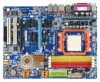
1394 USB Socket AM2 USB CPU_FAN AUDIO1 Marvell 88E1116 GA-M55SLI-S4 AUDIO2 PCIE_12V F_AUDIO PCIE_1 CODEC PCIE_16_1 PCIE_2 NV_SLI2 NV_SLI3 CD_IN PCIE_3 NV_SLI4 NV_SLI1 NV_SLI5 PCIE_16_2 nVIDIA® nForce 4 SLI CI PCI1 IT8716 SPDIF_I REV : 1.0 PCI2 FDD BIOS TSB43AB23 F1_1394 - Gigabyte GA-M55SLI-S4 | Manual - Page 9
1394 USB Socket AM2 USB CPU_FAN AUDIO1 Marvell 88E1116 GA-M55SLI-S4 AUDIO2 PCIE_12V F_AUDIO PCIE_1 CODEC PCIE_16_1 PCIE_2 NV_SLI2 NV_SLI3 CD_IN PCIE_3 NV_SLI4 NV_SLI1 NV_SLI5 PCIE_16_2 nVIDIA® nForce 4 SLI CI PCI1 IT8716 SPDIF_I REV : 2.0 PCI2 FDD BIOS TSB43AB23 F1_1394 - Gigabyte GA-M55SLI-S4 | Manual - Page 10
SLI Mode SLI Jumper AMD Socket AM2 CPU CPU CLK+/- (200 MHz) DDRII 400/533/667/800 MHz DIMM Dual Channel Memory Hyper Transport Bus RJ45 PCI Express x16 Bus PCI Express x1 Bus x1 x1 x1 PCIe CLK (100 MHz) 3 PCI Express x 1 Marvell 88E1116 PCI Bus TSB43AB23 3 IEEE 1394 2 PCI nVIDIA® nForce4 SLI - Gigabyte GA-M55SLI-S4 | Manual - Page 11
instructions below: 1. Please turn off the computer and unplug its power cord. 2. When handling the motherboard , avoid touching any metal leads or connectors. 3. It is best to wear an electrostatic discharge (ESD) cuff when handling electronic components (CPU motherboard problem manual - Gigabyte GA-M55SLI-S4 | Manual - Page 12
1-2 Feature Summary CPU Š Socket AM2 for AMD AthlonTM 64 FX / AthlonTM 64 X2 Dual-Core / AthlonTM 64 / SempronTM processor Front Side Bus Š 2000 MHz Chipset Š nVIDIA® nForce4 SLI chipset LAN Š Onboard Marvell 88E1116 PHY(10/100/1000 Mbit) Audio Š Onboard Realtek ALC850 CODEC Š Supports - Gigabyte GA-M55SLI-S4 | Manual - Page 13
Š Supports Xpress Install Š Supports Xpress Recovery2 Š Supports Xpress BIOS Rescue Bundle Software Š Norton Internet Security (OEM version) Form Factor Š ATX form factor; 30.5cm x 23.0cm (Note 1) Due to the limitation of Windows 32-bit operating system, when more than 4 GB of physical memory - Gigabyte GA-M55SLI-S4 | Manual - Page 14
on the middle of the CPU and gently press the metal lever back into its original position. Pin One Please use extra care when installing the CPU. The CPU will not fit if positioned incorrectly. Rather than applying force, please change the positioning of the CPU. GA-M55SLI-S4 Motherboard - 14 - - Gigabyte GA-M55SLI-S4 | Manual - Page 15
paste on the surface of the CPU. Install all the CPU cooler components (Please refer to the cooler manual for detailed installation instructions). Fig.2 Please connect the CPU cooler power connector to the CPU_FAN connector located on the motherboard so that the CPU cooler can properly function to - Gigabyte GA-M55SLI-S4 | Manual - Page 16
fit in one direction. Insert the DIMM memory module vertically into the DIMM socket. Then push it down. Fig.2 Close the plastic clip at both edges of the DIMM sockets to lock the DIMM module. Reverse the installation steps when you wish to remove the DIMM module. GA-M55SLI-S4 Motherboard - 16 - - Gigabyte GA-M55SLI-S4 | Manual - Page 17
English Dual Channel Memory Configuration The GA-M55SLI-S4 supports the Dual Channel Technology. After operating the Dual Channel Technology, the bandwidth of Memory Bus will add double. Due to CPU limitation, if you wish to operate the Dual Channel Technology, follow the guidelines below: 1. Dual - Gigabyte GA-M55SLI-S4 | Manual - Page 18
to the left shows to release the card. The motherboard includes a PCIE_12V power connector, which provides extra power to the onboard PCI Express x16 slot. When installing two graphics cards, please connect the power cable from the power supply to this connector. GA-M55SLI-S4 Motherboard - 18 - - Gigabyte GA-M55SLI-S4 | Manual - Page 19
) and the NVIDIA nForce4 SLI chipset. Together, the NVIDIA SLI technologies work seamlessly to allow two graphics cards to operate in parallel and share the work and deliver heartpounding PC performance. This section introduces steps to configure an SLI system on the GAM55SLI-S4 motherboard. Before - Gigabyte GA-M55SLI-S4 | Manual - Page 20
-RH) to the SLI gold edge connector on top of both cards. Make sure the two mini female slots on the bridge connector securely fit onto the SLI gold edge connetors of both cards. Female slots on the bridge connector Gold edge connector on the top of graphics card GA-M55SLI-S4 Motherboard - 20 - - Gigabyte GA-M55SLI-S4 | Manual - Page 21
cards, you must install the retention bracket included with the motherboard Card Driver Setting: Step 1: After installing graphics card driver in operating system, right-click the NVIDIA icon in your system tray and then select NVIDIA Display. The NVIDIA control panel will appear. Step 2: Select SLI - Gigabyte GA-M55SLI-S4 | Manual - Page 22
The S/PDIF optical output port is capable of providing digital audio to external speakers or compressed AC3 data to an external your OS supports USB controller. If your OS does not support USB controller, please contact OS vendor for possible patch or driver upgrade. GA-M55SLI-S4 Motherboard - 22 - - Gigabyte GA-M55SLI-S4 | Manual - Page 23
. Side Speaker Out The default Side Speaker Out jack. Surround side speakers can be connected to Side Speaker Out jack. Please refer to the 2-/4-/6-/8- channel audio setup steps for detailed software configuration information. - 23 - Hardware Installation - Gigabyte GA-M55SLI-S4 | Manual - Page 24
1) ATX_12V 2) ATX (Power Connector) 3) PCIE_12V 4) CPU_FAN 5) SYS_FAN 6) PWR_FAN 7) FDD 8) IDE1 / IDE2 9) SATAII0 / 1 / 2 / 3 10) PWR_LED 11) F_PANEL 12) F_AUDIO 13) CD_IN 14) SPDIF_I 15) F_USB1 / F_USB2 / F_USB3 16) F1_1394 / F2_1394 17) CI 18) CLR_CMOS 19) BATTERY GA-M55SLI-S4 Motherboard - 24 - Gigabyte GA-M55SLI-S4 | Manual - Page 25
cover on the power connector on the motherboard before plugging in the power cord ; otherwise, please do not remove it. 3 4 1 2 ATX_12V (rev. 1.0) 2 1 4 3 ATX_12V (rev. 2.0) Pin No. 1 2 3 4 Definition GND GND +12V +12V 12 24 1 13 ATX Pin No. 1 2 3 4 5 6 7 8 9 10 11 12 Definition - Gigabyte GA-M55SLI-S4 | Manual - Page 26
two graphics cards, please connect CPU/system/power from overheating and failure. 1 CPU_FAN CPU_FAN : Pin No. 1 2 3 4 Definition GND +12V / Speed Control Sense Speed Control 1 SYS_FAN / PWR_FAN SYS_FAN / PWR_FAN : Pin No. Definition 1 GND 2 +12V 3 Sense GA-M55SLI-S4 Motherboard - Gigabyte GA-M55SLI-S4 | Manual - Page 27
end of the cable connects to the FDD drive. The types of FDD drives supported are: 360 KB, 720 KB, 1.2 MB, 1.44 MB and 2.88 MB Master and the other as Slave (for information on settings, please refer to the instructions located on the IDE device). Before attaching the IDE cable, please take note of - Gigabyte GA-M55SLI-S4 | Manual - Page 28
3Gb/s Connectors, Controlled by nForce4 SLI) SATA 3Gb/s can provide up to 300 MB/s transfer rate. Please refer to the BIOS setting for the Serial ATA controller and install the proper driver in order to work properly Pin No. Definition 1 MPD+ 1 2 MPD- 3 MPD- GA-M55SLI-S4 Motherboard - 28 - - Gigabyte GA-M55SLI-S4 | Manual - Page 29
English 11) F_PANEL (Front Panel Jumper) Please connect the power LED, PC speaker, reset switch and power switch etc. of your chassis front panel to the F_PANEL connector according to the pin assignment below. Message LED/ Power/ Sleep LED Power Switch Speaker Connector MSG+ MSG- PW+ PWSPEAK+ - Gigabyte GA-M55SLI-S4 | Manual - Page 30
8 9 10 Definition MIC GND MIC_BIAS Power Front Audio (R) Rear Audio (R)/ Return R NC No Pin Front Audio (L) Rear Audio (L)/ Return L 13) CD_IN (CD In Connector) Connect CD-ROM or DVD-ROM audio out to the connector. 1 Pin No. 1 2 3 4 Definition CD-L GND GND CD-R GA-M55SLI-S4 Motherboard - 30 - - Gigabyte GA-M55SLI-S4 | Manual - Page 31
English 14) SPDIF_I (S/PDIF In Connector) Use S/PDIF IN feature only when your device has digital output function. Be careful with the polarity of the SPDIF_I connector. Check the pin assignment carefully while you connect the SPDIF cable, incorrect connection between the cable and connector will - Gigabyte GA-M55SLI-S4 | Manual - Page 32
Intrusion, Case Open) This 2-pin connector allows your system to detect if the chassis cover is removed. You can check the "Case Opened" status in BIOS Setup. 1 Pin No. Definition 1 Signal 2 GND GA-M55SLI-S4 Motherboard - 32 - - Gigabyte GA-M55SLI-S4 | Manual - Page 33
is incorrectly replaced. Replace only with the same or equivalent type recommended by the manufacturer. Dispose of used batteries according to the manufacturer's instructions. If you want to erase CMOS... 1. Turn off the computer and unplug the power cord. 2. Gently take out the battery and put it - Gigabyte GA-M55SLI-S4 | Manual - Page 34
English GA-M55SLI-S4 Motherboard - 34 - - Gigabyte GA-M55SLI-S4 | Manual - Page 35
BIOS, either GIGABYTE's Q-Flash or @BIOS utility can be used. Q-Flash allows the user to quickly and easily update or backup BIOS without entering the operating system. @BIOS is a Windows-based utility that does not require users to boot to DOS before upgrading BIOS but directly download and update - Gigabyte GA-M55SLI-S4 | Manual - Page 36
English : Boot Menu Select boot sequence for onboard (or add-on cards) device. Award Modular BIOS v6.00PG, An Energy Star Ally Copyright (C) 1984-2006, Award Software, Inc. GA-M55SLI-S4 F6a . . . . :BIOS Setup/Q-Flash, : Xpress Recovery2, : Boot Menu 10/11/2006-NF-CK804- - Gigabyte GA-M55SLI-S4 | Manual - Page 37
setup page includes all the items in standard compatible BIOS. „ Advanced BIOS Features This setup page includes all the items of fan, speed. „ MB Intelligent Tweaker(M.I.T.) This setup page is control CPU clock and frequency ratio. „ Load Optimized Defaults Optimized Defaults indicates the value - Gigabyte GA-M55SLI-S4 | Manual - Page 38
. You can use one of two methods: • Auto Allows BIOS to automatically detect IDE/SATA devices during POST(default) • None Select this if no IDE/SATA devices are used and the system will skip the automatic detection step and allow for faster system start up. GA-M55SLI-S4 Motherboard - 38 - - Gigabyte GA-M55SLI-S4 | Manual - Page 39
memory installed on the motherboard, or 640K for systems with 640K or more memory installed on the motherboard. Extended Memory The BIOS determines how much extended memory is present during the POST. This is the amount of memory located above 1 MB in the CPU's memory address map. - 39 - BIOS - Gigabyte GA-M55SLI-S4 | Manual - Page 40
on cards) BIOS can not tell from 720 K, 1.2 M or 1.44 M drive type as they are all 80 tracks. Disabled BIOS will not search for the type of floppy disk drive by track number. Note that there will not be any warning message if the drive installed is 360 K. (Default value) GA-M55SLI-S4 Motherboard - Gigabyte GA-M55SLI-S4 | Manual - Page 41
in Windows XP card and a PCI Express VGA card on the motherboard. PCI slot Set Init display first to PCI. PEG Set Init display first to PCI Express VGA card (the PCIE_16_1 slot). (Default value) PEG (Slot2) Set Init display first to PCI Express VGA card (the PCIE_16_2 slot). - 41 - BIOS - Gigabyte GA-M55SLI-S4 | Manual - Page 42
-ATA 2 x NV SATA 2 Primary RAID x NV SATA 2 Secondary RAID IDE Prefetch Mode USB Memory Type AC97 Audio ` SMART LAN Onboard 1394 Onboard Serial Port 1 Onboard Parallel Port [Enabled] [Enabled] [Enabled] value) Disabled Disable this function. F1: General Help GA-M55SLI-S4 Motherboard - 42 - - Gigabyte GA-M55SLI-S4 | Manual - Page 43
chipset. (Default value) Disabled Disable the LAN controller built-in core chipset Serial ATA 1 supported. NV SATA Memory Type SHADOW Set USB memory type to SHADOW. (Default value) Base Memory(640K) Set USB memory type to base memory(640K). AC97 Audio Auto Disabled Enable onboard AC'97 audio - Gigabyte GA-M55SLI-S4 | Manual - Page 44
the approximate length of the attached LAN cable. When a Cable Problem Occurs... If a cable problem occurs on a specified pair of wires, the Status field to the motherboard, the Status fields of all four pairs of wires will show Open and the Length fields show 0.0m. GA-M55SLI-S4 Motherboard - 44 - - Gigabyte GA-M55SLI-S4 | Manual - Page 45
Disabled Disable onboard IEEE 1394 function. Onboard Serial Port 1 Auto BIOS will automatically setup the Serial port 1 address. 3F8/IRQ4 1.1 controller. Legacy USB Keyboard/Storage Enabled Disabled Enable USB keyboard support in the MS-DOS environment. Disable this function. (Default value - Gigabyte GA-M55SLI-S4 | Manual - Page 46
suspend if button is pressed less than 4 seconds. PME Event Wake Up This feature requires an ATX power supply that provides at least 1A on the 5VSB lead. Disabled Enabled Disable this function. Enable 1~31 Time (hh: mm: ss) Alarm : (0~23) : (0~59) : (0~59) GA-M55SLI-S4 Motherboard - 46 - - Gigabyte GA-M55SLI-S4 | Manual - Page 47
, the system will be in "Off" state. Full-On (Default value) When AC-power back to the system, the system always in "On" state. - 47 - BIOS Setup - Gigabyte GA-M55SLI-S4 | Manual - Page 48
) Set IRQ 3,4,5,7,9,10,11,12,14,15 to PCI 2. Auto assign IRQ to PCI 1. (Default value) Set IRQ 3,4,5,7,9,10,11,12,14,15 to PCI 1. GA-M55SLI-S4 Motherboard - 48 - - Gigabyte GA-M55SLI-S4 | Manual - Page 49
/ 176oF. Monitor System/CPU temperature at 90oC / 194oF. Disable this function. (Default value) CPU/SYSTEM/POWER FAN Fail Warning Disabled Enabled Disable the CPU/System/Power fan fail warning function. (Default value) Enable the CPU/System/Power fan fail warning function. - 49 - BIOS Setup - Gigabyte GA-M55SLI-S4 | Manual - Page 50
. (Default Value) Voltage Set to Voltage when you use a CPU fan with a 3-pin fan power cable. PWM Set to PWM when you use a CPU fan with a 4-pin fan power cable. (Note) Whether the CPU Smart FAN Control function is supported will depend on the CPU you install. GA-M55SLI-S4 Motherboard - 50 - - Gigabyte GA-M55SLI-S4 | Manual - Page 51
using these features may result in system instability or corruption. Doing a overclock or overvoltage on CPU, chipsets and memory modules may result in damages or shortened life expectancy to these components value) Increase Southbridge and PCI Express bus voltage by 0.1V to 0.3V. - 51 - BIOS Setup - Gigabyte GA-M55SLI-S4 | Manual - Page 52
. Robust Graphics Booster Select the options can enhance the VGA graphics card bandwidth to get higher performance. Auto Set Robust Graphics Booster to Auto. (Default value) Fast Turbo Set Robust Graphics Booster to Fast. Set Robust Graphics Booster to Turbo. GA-M55SLI-S4 Motherboard - 52 - - Gigabyte GA-M55SLI-S4 | Manual - Page 53
Saving KLJI: Select Item F10: Save & Exit Setup Load Optimized Defaults Selecting this field loads the factory defaults for BIOS and Chipset Features which the system automatically detects. 2-9 Set Supervisor/User Password CMOS Setup Utility-Copyright (C) 1984-2006 Award Software ` Standard - Gigabyte GA-M55SLI-S4 | Manual - Page 54
CMOS Setup Utility-Copyright (C) 1984-2006 Award Software ` Standard CMOS Features ` Advanced BIOS Features ` Integrated Peripherals ` Power Management Setup ` PnP/PCI Configurations ` PC Health Status saving to RTC CMOS. Type "N" will return to Setup Utility. GA-M55SLI-S4 Motherboard - 54 - - Gigabyte GA-M55SLI-S4 | Manual - Page 55
shown in Windows XP. Insert the driver CD-title that came with your motherboard into your CD-ROM drive, the driver CD-title will auto start and show the installation guide. If not, please double click the CD-ROM device icon in "My computer", and execute the Run.exe. 3-1 Install Chipset Drivers After - Gigabyte GA-M55SLI-S4 | Manual - Page 56
Applications This page displays all the tools that Gigabyte developed and some free software, you can choose anyone you want and press "install" to install them. 3-3 Driver CD Information This page lists the contents of software and drivers in this CD-title. GA-M55SLI-S4 Motherboard - 56 - - Gigabyte GA-M55SLI-S4 | Manual - Page 57
English 3-4 Hardware Information This page lists all device you have for this motherboard. 3-5 Contact Us Please see the last page for details. - 57 - Drivers Installation - Gigabyte GA-M55SLI-S4 | Manual - Page 58
English GA-M55SLI-S4 Motherboard - 58 - - Gigabyte GA-M55SLI-S4 | Manual - Page 59
5 presents the most convenient Windows based system performance enhancement and manageability utility. Featuring several powerful yet easy to use tools such as 1) Overclocking for enhancing system performance, 2) C.I.A. and M.I.B. for special enhancement for CPU and Memory, 3) Smart-Fan control for - Gigabyte GA-M55SLI-S4 | Manual - Page 60
. Supporting Microsoft operating systems including Windows XP bytes of system memory 3. VESA-supported VGA cards How to use BIOS v6.00PG, An Energy Star Ally Copyright (C) 1984-2006, Award Software, Inc. GA-M55SLI-S4 F6a . . . . :BIOS drivers as well as software. GA-M55SLI-S4 Motherboard - 60 - - Gigabyte GA-M55SLI-S4 | Manual - Page 61
Windows 2000, be sure to execute the EnableBigLba.exe program from the driver CD before data backup. 2. It is normal that data backup takes longer time than data restoration. 3. Xpress Recovery2 is compliant with the GPL regulations. 4. On a few motherboards based on Nvidia chipsets, BIOS update - Gigabyte GA-M55SLI-S4 | Manual - Page 62
Part One. If your motherboard has single-BIOS, please refer to Part Two. Part One: Updating BIOS with Q-FlashTM Utility on Dual BIOS Motherboards. Some of Gigabyte motherboards are equipped with dual BIOS. In the BIOS menu of the motherboards supporting Q-Flash and Dual BIOS, the Q-Flash utility and - Gigabyte GA-M55SLI-S4 | Manual - Page 63
Backup Load Default Settings Save Settings to CMOS Q-Flash Utility Load Main BIOS from Floppy Load Backup BIOS from Floppy Save Main BIOS to Floppy Save Backup BIOS to Floppy Enter : Run :Move ESC:Reset F10:Power Off Dual BIOS utility bar Q-FlashTM utility title bar Action bar Task menu for - Gigabyte GA-M55SLI-S4 | Manual - Page 64
Save Main BIOS to Floppy Save Backup BIOS to Floppy Enter : Run :Move ESC:Reset F10:Power Off Do not turn off power or reset your system at this stage!! After BIOS file is read, you'll see a confirmation dialog box asking you "Are you sure to update BIOS?" GA-M55SLI-S4 Motherboard - 64 - Gigabyte GA-M55SLI-S4 | Manual - Page 65
Fab after updating. Award Modular BIOS v6.00PG, An Energy Star Ally Copyright (C) 1984-2003, Award Software, Inc. Intel i875P AGPset BIOS for 8KNXP Ultra Fba Check System Health OK , VCore = 1.5250 Main Processor : Intel Pentium(R) 4 1.6GHz (133x12) Memory Testing - Gigabyte GA-M55SLI-S4 | Manual - Page 66
save and exit. Part Two: Updating BIOS with Q-FlashTM Utility on Single-BIOS Motherboards. This part guides users of single-BIOS motherboards how to update BIOS using the Q-FlashTM utility. CMOS Setup Select Item F10: Save & Exit Setup Time, Date, Hard Disk Type... GA-M55SLI-S4 Motherboard - 66 - - Gigabyte GA-M55SLI-S4 | Manual - Page 67
Q-FlashTM utility Enter : Run Keep DMI Data Enable Update BIOS from Floppy Save BIOS to Floppy :Move ESC:Reset F10:Power Off Action download one BIOS file to the floppy disk so only one BIOS file, 8GE800.F4, is listed. Please confirm again you have the correct BIOS file for your motherboard - Gigabyte GA-M55SLI-S4 | Manual - Page 68
03/18/2003-I845GE-6A69YG01C-00 6. Press Del to enter BIOS menu after system reboots and "Load BIOS Optimized Defaults". See how to Load BIOS Optimized Defaults, please kindly refer to Step 6 to 7 in Part One. Congratulation!! You have updated BIOS successfully!! GA-M55SLI-S4 Motherboard - 68 - - Gigabyte GA-M55SLI-S4 | Manual - Page 69
the new @BIOS utility. @BIOS allows users to update their BIOS under Windows. Just select the desired @BIOS server to download the latest version of BIOS. Fig 1. Installing the @BIOS utility Fig 2. Installation Complete and Run @BIOS Click Start/ Programs/ Gigabyte/ BIOS/ @BIOS Select @BIOS item - Gigabyte GA-M55SLI-S4 | Manual - Page 70
BIOSTM server, please go onto Gigabyte's web site for downloading and updating it according to method II. IV. Please note that any interruption during updating will cause system unbooted. V. Do not use @BIOS and C.O.M. (Corporate Online Management) at the same time. GA-M55SLI-S4 Motherboard - 70 - - Gigabyte GA-M55SLI-S4 | Manual - Page 71
BIOS Setup. (3) Configure RAID set in RAID BIOS. (Note ) (4) Make a floppy disk containing the SATA controller driver. (Note ) (5) Install the SATA controller driver formatted floppy disk. (Note) (c) Windows XP/2000 setup disk. (d) Driver CD for your motherboard. (Note) (1) Installing SATA hard - Gigabyte GA-M55SLI-S4 | Manual - Page 72
IDE Prefetch Mode USB Memory Type AC97 Audio SMART LAN Onboard 1394 BIOS Setup menus described in this section may not show the exact settings for your motherboard. The actual BIOS Setup menu options you will see shall depend on the motherboard you have and the BIOS version. GA-M55SLI-S4 Motherboard - Gigabyte GA-M55SLI-S4 | Manual - Page 73
English Step 2: To boot from Windows installation CD-ROM, set First Boot Device under the Advanced BIOS Features menu to CDROM (Figure 5). CMOS Setup Utility-Copyright (C) 1984-2006 Award Software Advanced BIOS Features Hard Disk Boot Priority First Boot Device Second Boot Device Third Boot - Gigabyte GA-M55SLI-S4 | Manual - Page 74
memory test begins and before the operating system boot begins, look for a message which says "Press F10 to enter RAID setup utility" (Figure 3). Hit the F10 key to enter the RAID BIOS setup utility. MediaShield ROM BIOS 6.55 Copyright (C) 2006 NVIDIA Popup Figure 4 GA-M55SLI-S4 Motherboard - 74 - - Gigabyte GA-M55SLI-S4 | Manual - Page 75
English Step 5: Next, select the hard drives which you wish to be included in the disk array. The Free Disks section displays the information about the currently installed SATA hard drives. Press the TAB key to move to the Free Disks section. Select the target hard drives using the UP or DOWN ARROW - Gigabyte GA-M55SLI-S4 | Manual - Page 76
, press Y to confirm or N to cancel. Press ENTER to return to the Array List screen. To exit the Nvidia RAID utility, press ESC in the main menu or Ctrl+X in the Array List screen. Now, you can proceed to install the SATA controller driver and operating system. GA-M55SLI-S4 Motherboard - 76 - - Gigabyte GA-M55SLI-S4 | Manual - Page 77
recognized during the Windows setup process. First of all, copy the driver for the SATA controller from the motherboard driver CD-ROM to a floppy disk. See the instructions below about how to copy the driver in MS-DOS mode(Note). Prepare a startup disk that has CD-ROM support and a blank formatted - Gigabyte GA-M55SLI-S4 | Manual - Page 78
manufacturer, press S. * If you do not have any device support disks from a mass storage device manufacturer, or do not want to specify additional mass storage devices for use with Windows, press ENTER. S=Specify Additional Device ENTER=Continue F3=Exit Figure 13 GA-M55SLI-S4 Motherboard - 78 - - Gigabyte GA-M55SLI-S4 | Manual - Page 79
ESC to return to the previous screen. NVIDIA RAID CLASS DRIVER (required) NVIDIA NForce Storage Controller (required) ENTER=Select F3=Exit Figure 14 Windows Setup Setup will load support for the following mass storage device(s): NVIDIA RAID CLASS DRIVER (required) * To specify additional SCSI - Gigabyte GA-M55SLI-S4 | Manual - Page 80
installing Windows XP, press F3. Enter= Continue R=Repair F3=Exit Figure 17 (Note: Each time you add a new hard drive to a RAID array, the RAID driver will have to be installed under Windows once for that hard drive. After that, the driver will not have to be installed.) GA-M55SLI-S4 Motherboard - Gigabyte GA-M55SLI-S4 | Manual - Page 81
in Windows XP) Stereo Speakers Connection and Settings: We recommend that you use the speaker with amplifier to acquire the best sound effect if the stereo output is applied. STEP 1: Connect the stereo speakers or earphone to "Line Out". Line Out STEP 2 : Following installation of the audio driver - Gigabyte GA-M55SLI-S4 | Manual - Page 82
a Sound Effect icon on the lower right hand taskbar. Click the icon to select the function. Front Speaker Out Rear Speaker Out STEP 3: Click "Speaker Configuration" then click on the left selection bar and select "4CH Speaker" to complete 4 channel audio configuration. GA-M55SLI-S4 Motherboard - Gigabyte GA-M55SLI-S4 | Manual - Page 83
channels to "Rear Speaker Out", and the Center/Subwoofer channels to "Center/Subwoofer Speaker Out". STEP 2 : Following installation of the audio driver, you find a Sound Effect icon on the lower right hand taskbar. Click the icon to select the function. Front Speaker Out Center/Subwoofer Speaker - Gigabyte GA-M55SLI-S4 | Manual - Page 84
installation of the audio driver, you find a Sound Effect icon on audio configuration. Front Speaker Out Center/Subwoofer Speaker Out Rear Speaker Out Side Speaker Out Sound Effect Configuration: At the sound effect menu, users can adjust sound option settings as desired. GA-M55SLI-S4 Motherboard - Gigabyte GA-M55SLI-S4 | Manual - Page 85
Troubleshooting Below is a collection of general asked questions. To check general asked questions based on a specific motherboard model, please log on to GIGABYTE's website. Question 1: I cannot see some options that were included in previous BIOS after updating BIOS steps in the manual. If your - Gigabyte GA-M55SLI-S4 | Manual - Page 86
814 Xian TEL: +86-29-85531943 FAX: +86-29-85539821 Shenyang TEL: +86-24-83992901 FAX: +86-24-83992909 y India GIGABYTE TECHNOLOGY (INDIA) LIMITED WEB address : http://www.gigabyte.in y Australia GIGABYTE TECHNOLOGY PTY. LTD. WEB address : http://www.gigabyte.com.au GA-M55SLI-S4 Motherboard - 86 - - Gigabyte GA-M55SLI-S4 | Manual - Page 87
BYTE Technology Co., Ltd. in SERBIA & MONTENEGRO WEB address : http://www.gigabyte.co.yu y GIGABYTE Global Service System To submit a technical or non-technical (Sales/ Marketing) question, please link to : http://ggts.gigabyte.com.tw Then select your language to enter the system. - 87 - Appendix - Gigabyte GA-M55SLI-S4 | Manual - Page 88
- 88 -
-
 1
1 -
 2
2 -
 3
3 -
 4
4 -
 5
5 -
 6
6 -
 7
7 -
8
-
9
-
10
-
11
-
12
-
13
-
14
-
15
-
16
-
17
-
18
-
19
-
20
-
21
-
22
-
23
-
24
-
25
-
26
-
27
-
28
-
29
-
30
-
31
-
32
-
33
-
34
-
35
-
36
-
37
-
38
-
39
-
40
-
41
-
42
-
43
-
44
-
45
-
46
-
47
-
48
-
49
-
50
-
51
-
52
-
53
-
54
-
55
-
56
-
57
-
58
-
59
-
60
-
61
-
62
-
63
-
64
-
65
-
66
-
67
-
68
-
69
-
70
-
71
-
72
-
73
-
74
-
75
-
76
-
77
-
78
-
79
-
80
-
81
-
82
-
83
-
84
-
85
-
86
-
87
-
88
 |
 |

GA-M55SLI-S4
AMD Socket AM2 Processor Motherboard
User's Manual
Rev. 200
2
12ME-M55SLIS4-200
2
R
*
The WEEE marking on the product indicates this product must not be disposed of with user's other household waste
and must be handed over to a designated collection point for the recycling of waste electrical and electronic equipment!!
*
The WEEE marking applies only in European Union's member states.