Gigabyte GA-M59SLI-S5 Manual
Gigabyte GA-M59SLI-S5 Manual
 |
View all Gigabyte GA-M59SLI-S5 manuals
Add to My Manuals
Save this manual to your list of manuals |
Gigabyte GA-M59SLI-S5 manual content summary:
- Gigabyte GA-M59SLI-S5 | Manual - Page 1
GA-M59SLI-S5 / GA-M59SLI-S4 AMD Socket AM2 Processor Motherboard User's Manual Rev. 1003 12ME-M59SLIS5-1003R * The WEEE marking on the product indicates this product must not be disposed of with user's other household waste and must be handed over to a designated collection point for the recycling - Gigabyte GA-M59SLI-S5 | Manual - Page 2
Motherboard GA-M59SLI-S5 / GA-M59SLI-S4 Jun. 8, 2006 Motherboard GA-M59SLI-S5 / GA-M59SLI-S4 Jun. 8, 2006 - Gigabyte GA-M59SLI-S5 | Manual - Page 3
product information and specifications, please carefully read the "Product User Manual". „ For detailed information related to Gigabyte's unique features, please go to the "Technology Guide" section on Gigabyte's website to read or download the information you need. For more product details, please - Gigabyte GA-M59SLI-S5 | Manual - Page 4
OptionalAccessories ...6 GA-M59SLI-S5 Motherboard Layout 7 GA-M59SLI-S4 Motherboard Layout 8 Block Diagram ...9 Chapter 1 Hardware Installation 11 1-1 Considerations Prior to Installation 11 1-2 Feature Summary 12 1-3 Installation of the CPU and CPU Cooler 15 1-3-1 Installation of the CPU 15 - Gigabyte GA-M59SLI-S5 | Manual - Page 5
SATA Hard Drive(s 79 A. nVIDIA® nForce 590SLI Southbridge 79 B. GIGABYTE SATA2 Controller 92 4-1-5 2- / 4- / 6- / 8- Channel Audio Function Introduction 104 A. Realtek ALC888DD CODEC 104 B. Realtek ALC883 CODEC 111 4-2 Troubleshooting 116 Only for GA-M59SLI-S5. Only for GA-M59SLI-S4. - 5 - - Gigabyte GA-M59SLI-S5 | Manual - Page 6
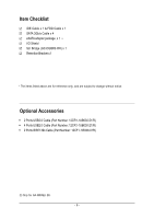
USB2.0 Cable (Part Number: 12CR1-1UB030-51/R) Š 4 Ports USB2.0 Cable (Part Number: 12CR1-1UB030-21/R) Š 2 Ports IEEE1394 Cable (Part Number: 12CF1-1IE008-01R) Only for GA-M59SLI-S5. - 6 - - Gigabyte GA-M59SLI-S5 | Manual - Page 7
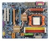
GA-M59SLI-S5 Motherboard Layout KB_MS OPTICAL ATX_12V_2X Socket AM2 R_1394 ATX COMA LPT USB LAN1 USB LAN2 F_AUDIO DDRII1 DDRII2 DDRII3 DDRII4 PWR_FAN CPU_FAN Marvell 88E1116 AUDIO PCIE_1 Marvell 88E1116 nVIDIA® nForce 590SLI Northbridge GA-M59SLI-S5 PCIE_16_1 IDE1 FDD SATAII5 SATAII4 - Gigabyte GA-M59SLI-S5 | Manual - Page 8
GA-M59SLI-S4 Motherboard Layout KB_MS OPTICAL ATX_12V Socket AM2 R_1394 ATX COMA LPT USB USB IDE1 CPU_FAN DDRII1 DDRII2 DDRII3 DDRII4 PWR_FAN LAN2 F_AUDIO AUDIO PCIE_1 Marvell 88E1116 nVIDIA® nForce 590SLI Northbridge GA-M59SLI-S4 PCIE_16_1 FDD SATAII5 SATAII4 SYS_FAN CODEC - Gigabyte GA-M59SLI-S5 | Manual - Page 9
AM2 CPU BIOS 6 SATA 3Gb/s ATA33/66/100/133 IDE Channel Floppy IT8716 LPT Port COM Port PS/2 KB/Mouse 2 PCI 10 USB Ports PCI Express x8 PCI Express x16 3 IEEE1394a Surround Speaker Out Center/Subwoofer Speaker Out Side Speaker Out MIC Line-Out Line-In SPDIF In SPDIF Out Only for GA-M59SLI-S5 - Gigabyte GA-M59SLI-S5 | Manual - Page 10
- 10 - - Gigabyte GA-M59SLI-S5 | Manual - Page 11
of violating the conditions recommended in the user manual. 3. Damage due to improper installation. 4. Damage due to use of uncertified components. 5. Damage due to use exceeding the permitted parameters. 6. Product determined to be an unofficial Gigabyte product. - 11 - Hardware Installation - Gigabyte GA-M59SLI-S5 | Manual - Page 12
memory)(Note 1) Š Supports dual channel DDRII 800/667/533/400 DIMMs Š Supports 1.8V DDRII DIMMs Š Supports ECC Memory Š 2 PCI Express x16 slot Š 1 PCI Express x8 slot Š 2 PCI Express x1 slots Š 2 PCI slots Only for GA-M59SLI-S5. Only for GA-M59SLI-S4. GA-M59SLI-S5/GA-M59SLI-S4 Motherboard - 12 - - Gigabyte GA-M59SLI-S5 | Manual - Page 13
port Š 6 audio jacks (Line In CPU / Power / System fan speed detection Š System / CPU warning temperature Š CPU fan failure warning Š Supports CPU Smart Fan function(Note 2) BIOS Š 2 4Mbit flash ROM Š Use of licensed AWARD BIOS Š Supports DualBIOS Only for GA-M59SLI-S5. Only for GA-M59SLI-S4 - Gigabyte GA-M59SLI-S5 | Manual - Page 14
64-bit operating system doesn't have such limitation. (Note 2) Whether the CPU Smart FAN Control function is supported will depend on the CPU you install. (Note 3) EasyTune functions may vary depending on different motherboards. (Note 4) Silent Pipe only for GA-M59SLI-S5. GA-M59SLI-S5/GA-M59SLI-S4 - Gigabyte GA-M59SLI-S5 | Manual - Page 15
please comply with the following conditions: 1. Please make sure that the motherboard supports the CPU. 2. Please take note of the pin 1 marking (the small triangle) on the CPU. If you install the CPU in the wrong direction, the CPU will not insert properly. If this occurs, please change the insert - Gigabyte GA-M59SLI-S5 | Manual - Page 16
The CPU cooler may adhere to the CPU as a result of hardening of the heat paste. To prevent such an occurrence, it is suggested that either thermal tape rather than heat paste be used for heat dissipation or using extreme care when removing the CPU cooler. GA-M59SLI-S5/GA-M59SLI-S4 Motherboard - 16 - Gigabyte GA-M59SLI-S5 | Manual - Page 17
can be installed in only one direction. If you are unable to insert the module, please switch the direction. The motherboard supports DDRII memory modules, whereby BIOS will automatically detect memory capacity and specifications. Memory modules are designed so that they can be inserted only in one - Gigabyte GA-M59SLI-S5 | Manual - Page 18
Configuration The GA-M59SLI-S5/GA-M59SLI-S4 supports the Dual Channel Technology. After operating the Dual Channel Technology, the bandwidth of Memory Bus will double. Due to CPU limitation, if recommend installing them in DDRII1 and DDRII2 DIMM sockets. GA-M59SLI-S5/GA-M59SLI-S4 Motherboard - 18 - - Gigabyte GA-M59SLI-S5 | Manual - Page 19
Read the related expansion card's instruction document before install the expansion Press the expansion card firmly into expansion slot in motherboard. 4. Be sure the metal contacts on the card if necessary, setup BIOS utility of expansion card from BIOS. 8. Install related driver from the operating - Gigabyte GA-M59SLI-S5 | Manual - Page 20
architecture, features hardware and software innovations within NVIDIA GPU ( GIGABYTE GV-NX76T256D-RH). If you want to set up a single graphics card system, we recommend installing the graphics card on the PCIE_16_1 slot to ensure better display performance. GA-M59SLI-S5/GA-M59SLI-S4 Motherboard - Gigabyte GA-M59SLI-S5 | Manual - Page 21
card Step 3: In order to securely fix the bridge connector beween the two cards, you must install the retention bracket included with the motherboard and secure the retention bracket to the chassis back panel with a screw. retention bracket place this part on the top of the bridge connector - Gigabyte GA-M59SLI-S5 | Manual - Page 22
Setting: Step 1: After installing graphics card driver in operating system, right-click the NVIDIA icon in your system tray and then select NVIDIA Display. GPU dialog box. System will restart after you click Apply. Then the SLI configuration is completed. GA-M59SLI-S5/GA-M59SLI-S4 Motherboard - 22 - - Gigabyte GA-M59SLI-S5 | Manual - Page 23
The SPDIF optical output port is capable of providing digital audio to external speakers or com pressed AC3 data to an OS supports USB controller. If your OS does not support USB controller, please contact OS vendor for possible patch or driver upgrade GA-M59SLI-S5. - 23 - Hardware Installation - Gigabyte GA-M59SLI-S5 | Manual - Page 24
default speakers settings, the ~ audio jacks can be reconfigured to perform different functions via the audio software. Only microphones still MUST be I SATAII4 / SATAII5 22) BAT 11) JSATAII0 / JSATAII1 Only for GA-M59SLI-S5. Only for GA-M59SLI-S4. GA-M59SLI-S5/GA-M59SLI-S4 Motherboard - 24 - - Gigabyte GA-M59SLI-S5 | Manual - Page 25
the motherboard before plugging in the power cord ; otherwise, please do not remove it. 3 4 1 2 ATX_12V Pin No. 1 2 3 4 Definition GND GND +12V +12V 5 8 1 4 ATX_12V_2X Pin No. 1 2 3 4 5 6 7 8 Definition GND GND GND GND +12V +12V +12V +12V Only for GA-M59SLI-S5. Only for GA-M59SLI-S4 - Gigabyte GA-M59SLI-S5 | Manual - Page 26
3.3V -12V GND PS_ON(soft On/Off) GND GND GND -5V +5V +5V +5V (Only for 24-pin ATX) GND(Only for 24-pin ATX) GA-M59SLI-S5/GA-M59SLI-S4 Motherboard - 26 - - Gigabyte GA-M59SLI-S5 | Manual - Page 27
Most coolers are designed with color-coded power connector wires. A red power connector wire indicates a positive connection and requires a +12V power voltage. The black connector wire is the ground wire (GND). Remember to connect the CPU/system fan cable to the CPU_FAN/SYS_FAN connector to prevent - Gigabyte GA-M59SLI-S5 | Manual - Page 28
Master and the other as Slave (for information on settings, please refer to the instructions located on the IDE device). Before attaching the IDE cable, please take note of the foolproof groove in the IDE connector. 40 39 2 1 Only for GA-M59SLI-S4. GA-M59SLI-S5/GA-M59SLI-S4 Motherboard - 28 - - Gigabyte GA-M59SLI-S5 | Manual - Page 29
of FDD drives supported are: 360KB, 720KB BIOS setting for the SATA 3Gb/s and install the proper driver in order to work properly. 7 1 SATAII5 SATAII4 1 7 Pin No. 1 2 3 4 5 6 7 Definition GND TXP TXN GND RXN RXP GND 7 17 1 SATAII1 SATAII3 SATAII0 1 71 SATAII2 7 Only for GA-M59SLI-S5 - Gigabyte GA-M59SLI-S5 | Manual - Page 30
1: Power Pin 2- Pin 3: NC Pin 4: Data(-) Open: Normal Close: Reset Hardware System Open: Normal Close: Power On/Off Pin 1: LED anode(+) Pin 2: LED cathode(-) NC GA-M59SLI-S5/GA-M59SLI-S4 Motherboard - 30 - - Gigabyte GA-M59SLI-S5 | Manual - Page 31
5 Line Out (R) 6 NC 7 NC 8 No Pin 9 Line Out (L) 10 NC By default, the audio driver is configured to support HD Audio. To connect an AC97 front panel audio module to this connector, please refer to the instructions on Page 106 about the software settings. - 31 - Hardware Installation - Gigabyte GA-M59SLI-S5 | Manual - Page 32
English 15) CD_IN (CD In Connector) Connect CD-ROM or DVD-ROM audio out to the connector. Pin No. Definition 1 CD-L 2 GND 3 GND 1 4 CD-R 16) SPDIF_I cable, please contact your local dealer. Pin No. Definition 1 Power 2 SPDIFI 3 GND 1 GA-M59SLI-S5/GA-M59SLI-S4 Motherboard - 32 - - Gigabyte GA-M59SLI-S5 | Manual - Page 33
English 17) F_USB1/F_USB2/F_USB3 (Front USB Connectors) Be careful with the polarity of the front USB connector. Check the pin assignment carefully while you connect the front USB cable, incorrect connection between the cable and connector will make the device unable to work or even damage it. For - Gigabyte GA-M59SLI-S5 | Manual - Page 34
CMOS, temporarily short the two pins. Default doesn't include the jumper to avoid improper use of this header. Open: Normal Short: Clear CMOS Only for GA-M59SLI-S5. GA-M59SLI-S5/GA-M59SLI-S4 Motherboard - 34 - - Gigabyte GA-M59SLI-S5 | Manual - Page 35
chassis cover is removed. You can check the "Case Opened" status in BIOS Setup. Pin No. Definition 1 1 Signal 2 GND 22) BATTERY Danger by the manufacturer. Dispose of used batteries according to the manufacturer's instructions. If you want to erase CMOS... 1. Turn off the computer - Gigabyte GA-M59SLI-S5 | Manual - Page 36
English GA-M59SLI-S5/GA-M59SLI-S4 Motherboard - 36 - - Gigabyte GA-M59SLI-S5 | Manual - Page 37
BIOS, either Gigabyte's Q-Flash or @BIOS utility can be used. Q-Flash allows the user to quickly and easily update or backup BIOS without entering the operating system. @BIOS is a Windows-based utility that does not require users to boot to DOS before upgrading BIOS but directly download and update - Gigabyte GA-M59SLI-S5 | Manual - Page 38
from BIOS If your system becomes unstable and you load the default BIOS settings, you can use this function to reload the CMOS settings with a CMOS settings profile created before, without the hassles of resetting the CMOS configurations. Only for GA-M59SLI-S5. GA-M59SLI-S5/GA-M59SLI-S4 Motherboard - Gigabyte GA-M59SLI-S5 | Manual - Page 39
items in standard compatible BIOS. „ Advanced BIOS Features This setup page fan, speed. „ MB Intelligent Tweaker(M.I.T.) This setup page is control CPU clock and frequency ratio. to the system and Setup, or just to Setup. „ Set User Password Change, set, or disable password. It allows you to limit - Gigabyte GA-M59SLI-S5 | Manual - Page 40
is , , , . Week The week, from Sun to Sat, determined by the BIOS and is display only Month The month, Jan. Through Dec. Day The day, from 1 to 31 (or the maximum allowed in the month) Year The year, from 1999 through 2098 GA-M59SLI-S5/GA-M59SLI-S4 Motherboard - 40 - - Gigabyte GA-M59SLI-S5 | Manual - Page 41
of three methods: Auto Allows BIOS to automatically detect IDE devices during POST(default) None Select this if no IDE devices are used and the system will skip the automatic detection step and allow for faster system start up. Manual User can manually input the correct settings Access Mode - Gigabyte GA-M59SLI-S5 | Manual - Page 42
motherboard, or 640K for systems with 640K or more memory installed on the motherboard. Extended Memory The BIOS determines how much extended memory is present during the POST. This is the amount of memory located above 1 MB in the CPU's memory address map. GA-M59SLI-S5/GA-M59SLI-S4 Motherboard - Gigabyte GA-M59SLI-S5 | Manual - Page 43
Utility-Copyright (C) 1984-2006 Award Software Advanced BIOS Features Hard Disk Boot Priority : General Help F11/12: Profile F5: Previous Values F6: Fail-Safe Defaults F7: Optimized Defaults Hard Disk Boot Priority Select boot sequence for onboard(or add-on cards) SCSI, RAID, etc. Use < > or - Gigabyte GA-M59SLI-S5 | Manual - Page 44
motherboard. PCI slot PEG Set Init display first to PCI. Set Init display first to PCI Express VGA card. (Default value) PEG (Slot2) Set Init display first to PCI Express VGA card(Slot2). PEG (Slot3) Set Init display first to PCI Express VGA card(Slot3). GA-M59SLI-S5/GA-M59SLI-S4 Motherboard - Gigabyte GA-M59SLI-S5 | Manual - Page 45
RAID [Disabled] Disabled Disabled Disabled Disabled Disabled Disabled Item Help Menu Level : Move Enter: Select +/-/PU/PD: Value F10: Save ESC: Exit F1: General Help F11/12: Profile F5: Previous Values F6: Fail-Safe Defaults F7: Optimized Defaults Only for GA-M59SLI-S5. - 45 - BIOS - Gigabyte GA-M59SLI-S5 | Manual - Page 46
. IDE Prefetch Mode Enabled Enable IDE Prefetch mode. (Default value) Disabled Disable IDE Prefetch mode. Onboard Audio Function Auto Auto-detect onboard audio function. (Default value) Disabled Disable this function. Only for GA-M59SLI-S5. GA-M59SLI-S5/GA-M59SLI-S4 Motherboard - 46 - - Gigabyte GA-M59SLI-S5 | Manual - Page 47
Setup Utility-Copyright (C) 1984-2006 Award Software SMART LAN Start detecting at Port 0. F5: Previous Values F6: Fail-Safe Defaults F7: Optimized Defaults This motherboard a Cable Problem Occurs... If a cable problem occurs on a specified pair of wires, the GA-M59SLI-S5. - 47 - BIOS Setup - Gigabyte GA-M59SLI-S5 | Manual - Page 48
) USB Mouse Support Enabled Disabled Enable USB mouse support. Disable USB mouse support. (Default value) Legacy USB Storage detect Enabled Disabled Enable USB storage detect function. (Default value) Disable this function. Only for GA-M59SLI-S5. GA-M59SLI-S5/GA-M59SLI-S4 Motherboard - 48 - - Gigabyte GA-M59SLI-S5 | Manual - Page 49
Utility-Copyright (C) 1984-2006 Award Software Power Management Setup ACPI Suspend : Value F10: Save ESC: Exit F1: General Help F11/12: Profile F5: Previous Values F6: Fail-Safe Defaults F7: Optimized Defaults ACPI Suspend Type S1(POS) Set ACPI (0~23) : (0~59) : (0~59) - 49 - BIOS Setup - Gigabyte GA-M59SLI-S5 | Manual - Page 50
system, the system will be in "Off" state. (Default value) Full-On When AC-power back to the system, the system always in "On" state. GA-M59SLI-S5/GA-M59SLI-S4 Motherboard - 50 - - Gigabyte GA-M59SLI-S5 | Manual - Page 51
Software PnP/PCI Configurations PCI 2 IRQ Assignment PCI 1 IRQ Assignment [Auto] [Auto] Item Help Menu Level : Move Enter: Select +/-/PU/PD: Value F10: Save ESC: Exit F1: General Help F11/12: Profile F5: Previous Values F6 value) Set IRQ 3,4,5,7,9,10,11,12,14,15 to PCI 1. - 51 - BIOS Setup - Gigabyte GA-M59SLI-S5 | Manual - Page 52
176oF. 90oC / 194oF Monitor System/CPU temperature at 90oC / 194oF. Disabled Disable this function. (Default value) CPU FAN Fail Warning Disabled Enabled Disable CPU fan fail warning function. (Default value) Enable CPU fan fail warning function. GA-M59SLI-S5/GA-M59SLI-S4 Motherboard - 52 - - Gigabyte GA-M59SLI-S5 | Manual - Page 53
F1: General Help F5: Previous Values F6: Fail-Safe Defaults F7: Optimized Defaults Incorrect using these features may cause your system broken. For power end-user use only. CPU Frequency(MHz) Auto BIOS will automatically setup the CPU Frequency(MHz). 100 ~ 500 Set CPU frequency from 100MHz - Gigabyte GA-M59SLI-S5 | Manual - Page 54
Control Please note that by overclocking your system through the increase of CPU and Northbridge. Normal Set CPU HT-Link voltage to Normal. (Default value) +0.1V +0.2V +0.3V Set CPU HT-Link voltage to +0.1V. Set CPU HT-Link voltage to +0.2V. Set CPU GA-M59SLI-S5/GA-M59SLI-S4 Motherboard - 54 - - Gigabyte GA-M59SLI-S5 | Manual - Page 55
1V +0.2V +0.3V Set Northbridge/PCIE voltage to +0.1V. Set Northbridge/PCIE voltage to +0.2V. Set Northbridge/PCIE voltage to +0.3V. CPU Voltage Control Supports adjustable CPU Vcore from 0.800V to 1.550V. (Default value: Normal) Normal CPU Vcore Display your CPU Vcore voltage. - 55 - BIOS Setup - Gigabyte GA-M59SLI-S5 | Manual - Page 56
: Select Item F10: Save & Exit Setup F11: Save CMOS to BIOS F12: Load CMOS from BIOS Load Optimized Defaults Selecting this field loads the factory defaults for BIOS and Chipset Features which the system automatically detects. Only for GA-M59SLI-S5. GA-M59SLI-S5/GA-M59SLI-S4 Motherboard - 56 - - Gigabyte GA-M59SLI-S5 | Manual - Page 57
English 2-10 Set Supervisor/User Password CMOS Setup Utility-Copyright (C) 1984-2006 Award Software Standard CMOS Features Advanced BIOS Features Integrated Peripherals Power Management Setup PnP/PCI ConfiguratioEnsnter Password: PC Health Status MB Intelligent Tweaker(M.I.T.) Load Fail-Safe - Gigabyte GA-M59SLI-S5 | Manual - Page 58
F8: Dual BIOS 1/Q-Flash : Select Item F10: Save & Exit Setup Abandon all Data F11: Save CMOS to BIOS F12: Load CMOS from BIOS Type "Y" will quit the Setup Utility without saving to RTC CMOS. Type "N" will return to Setup Utility. Only for GA-M59SLI-S5. GA-M59SLI-S5/GA-M59SLI-S4 Motherboard - 58 - Gigabyte GA-M59SLI-S5 | Manual - Page 59
- 59 - BIOS Setup English - Gigabyte GA-M59SLI-S5 | Manual - Page 60
English GA-M59SLI-S5/GA-M59SLI-S4 Motherboard - 60 - - Gigabyte GA-M59SLI-S5 | Manual - Page 61
will continue to install other drivers. System will reboot automatically after install the drivers, afterward you can install others application. For USB2.0 driver support under Windows XP operating system, please use Windows Service Pack. After install Windows Service Pack, it will show a question - Gigabyte GA-M59SLI-S5 | Manual - Page 62
This page displays all the tools that Gigabyte developed and some free software, you can choose anyone you want and press "install" to install them. 3-3 Driver CD Information This page lists the contents of software and drivers in this CD-title. GA-M59SLI-S5/GA-M59SLI-S4 Motherboard - 62 - - Gigabyte GA-M59SLI-S5 | Manual - Page 63
English 3-4 Hardware Information This page lists all device you have for this motherboard. 3-5 Contact Us Please see the last page for details. - 63 - Drivers Installation - Gigabyte GA-M59SLI-S5 | Manual - Page 64
English GA-M59SLI-S5/GA-M59SLI-S4 Motherboard - 64 - - Gigabyte GA-M59SLI-S5 | Manual - Page 65
model support these Unique Software Utilities, please check your MB features.) 4-1-1 EasyTune 5 Introduction EasyTune 5 presents the most convenient Windows based system performance enhancement and manageability utility. Featuring several powerful yet easy to use tools such as 1) Overclocking for - Gigabyte GA-M59SLI-S5 | Manual - Page 66
of hard disk data. Supporting Microsoft operating systems including Windows XP/2000/NT/98/Me Modular BIOS v6.00PG, An Energy Star Ally Copyright (C) 1984-2006, Award Software, Inc. GA-M59SLI-S5 E18 . . . . :BIOS drivers as well as software. GA-M59SLI-S5/GA-M59SLI-S4 Motherboard - 66 - - Gigabyte GA-M59SLI-S5 | Manual - Page 67
Windows 2000, be sure to execute the EnableBigLba.exe program from the driver CD before data backup. 2. It is normal that data backup takes longer time than data restoration. 3. Xpress Recovery2 is compliant with the GPL regulations. 4. On a few motherboards based on Nvidia chipsets, BIOS update - Gigabyte GA-M59SLI-S5 | Manual - Page 68
Settings Save Settings to CMOS Q-Flash Utility Update Main BIOS from Floppy Update Backup BIOS from Floppy Save Main BIOS to Floppy Save Backup BIOS to Floppy PgDn/PgUp: Modify : Move ESC: Reset 512K 512K F10: Power Off Only for GA-M59SLI-S5. GA-M59SLI-S5/GA-M59SLI-S4 Motherboard - 68 - - Gigabyte GA-M59SLI-S5 | Manual - Page 69
. Update ESCD failure, checksum error or reset? occurs in the Main BIOS, just BIOS occurs a checksum error or the Main BIOS occurs a WIDE RANGE PROTECTION error and Halt On Error set to Enable, the PC will show messages on the boot screen, and the system will pause and wait for the user's instruction - Gigabyte GA-M59SLI-S5 | Manual - Page 70
Primary Master : FUJITSU MPE3170AT ED-03-08 Primary Slave : None Secondary Master : CREATIVEDVD-RM DVD1242E BC101 Secondary Slave : None Press DEL to enter SETUP / Dual BIOS / Q-Flash / F9 For Xpress Recovery 08/07/2003-i875P-6A79BG03C-00 GA-M59SLI-S5/GA-M59SLI-S4 Motherboard - 70 - - Gigabyte GA-M59SLI-S5 | Manual - Page 71
1984-2004 Award Software Standard CMOS Features Advanced BIOS Features Integrated Peripherals Power Management Setup PnP/PCI Configurations PC Health Status MB Intelligent Tweaker(M.I.T.) Select Language Load Fail-Safe Defaults Load Optimized Defaults Set Supervisor Password Set User Password Save - Gigabyte GA-M59SLI-S5 | Manual - Page 72
Main BIOS to Floppy Save Backup BIOS to Floppy Enter : Run :Move ESC:Reset F10:Power Off Do not turn off power or reset your system at this stage!! After BIOS file is read, you'll see a confirmation dialog box asking you "Are you sure to update BIOS?" GA-M59SLI-S5/GA-M59SLI-S4 Motherboard - Gigabyte GA-M59SLI-S5 | Manual - Page 73
on your boot screen becomes the one you flashed. The BIOS file becomes Fab after updating. Award Modular BIOS v6.00PG, An Energy Star Ally Copyright (C) 1984-2003, Award Software, Inc. Intel i875P AGPset BIOS for 8KNXP Ultra Fba Check System Health OK , VCore = 1.5250 Main Processor : Intel - Gigabyte GA-M59SLI-S5 | Manual - Page 74
part guides users of single-BIOS motherboards how to update BIOS using the Q-FlashTM utility. CMOS Setup Utility-Copyright (C) 1984-2004 Award Software Standard CMOS Features Advanced BIOS Features Integrated Peripherals Power Management Setup PnP/PCI Configurations PC Health Status MB Intelligent - Gigabyte GA-M59SLI-S5 | Manual - Page 75
Q-FlashTM utility Enter : Run Keep DMI Data Enable Update BIOS from Floppy Save BIOS to Floppy :Move ESC:Reset F10:Power Off Action download one BIOS file to the floppy disk so only one BIOS file, 8GE800.F4, is listed. Please confirm again you have the correct BIOS file for your motherboard - Gigabyte GA-M59SLI-S5 | Manual - Page 76
-I845GE-6A69YG01C-00 6. Press Del to enter BIOS menu after system reboots and "Load BIOS Fail-Safe Defaults". See how to Load BIOS Fail-Safe Defaults, please kindly refer to Step 6 to 7 in Part One. Congratulation!! You have updated BIOS successfully!! GA-M59SLI-S5/GA-M59SLI-S4 Motherboard - 76 - - Gigabyte GA-M59SLI-S5 | Manual - Page 77
the new @BIOS utility. @BIOS allows users to update their BIOS under Windows. Just select the desired @BIOS server to download the latest version of BIOS. Fig 1. Installing the @BIOS utility Fig 2. Installation Complete and Run @BIOS Click Sart/ Programs/ GIGABYTE/@BIOS Select @BIOS item than - Gigabyte GA-M59SLI-S5 | Manual - Page 78
, please go onto Gigabyte's web site for downloading and updating it according to method II. IV. Please note that any interruption during updating will cause system unbooted. V. Do not use @BIOS and C.O.M. (Corporate Online Management) at the same time. GA-M59SLI-S5/GA-M59SLI-S4 Motherboard - 78 - - Gigabyte GA-M59SLI-S5 | Manual - Page 79
one SATA controller on your motherboard, you may refer to the motherboard user's manual to identify the SATA controller for the connector. Then connect the power connector from your power supply to the hard drive. "*" Skip this step if you do not want to create RAID array on the SATA controller - Gigabyte GA-M59SLI-S5 | Manual - Page 80
F6: Fail-Safe Defaults F7: Optimized Defaults Figure 2 The BIOS Setup menus described in this section may not show the exact settings for your motherboard. The actual BIOS Setup menu options you will see shall depend on the motherboard you have and the BIOS version. GA-M59SLI-S5/GA-M59SLI-S4 - Gigabyte GA-M59SLI-S5 | Manual - Page 81
Windows installation CD-ROM, set First Boot Device under the Advanced BIOS Features menu to CDROM (Figure 3). CMOS Setup Utility-Copyright (C) 1984-2006 Award Software Advanced BIOS F1: General Help F5: Previous Values F6: Fail-Safe Defaults F7: Optimized Defaults Figure 3 Step 3: Save and exit - Gigabyte GA-M59SLI-S5 | Manual - Page 82
RAID setup utility" (Figure 4). Hit the F10 key to enter the RAID BIOS setup utility. MediaShield IDE ROM BIOS 6.55 Copyright (C) 2006 NVIDIA Corp. Detecting array ... Press F10 to enter RAID [F6] Back [F7] Finish [TAB] Navigate [ ] Select [ENTER] Popup Figure 5 GA-M59SLI-S5/GA-M59SLI-S4 Motherboard - Gigabyte GA-M59SLI-S5 | Manual - Page 83
key to add the hard drives to the Array Disks section (Figure 6). RAID Mode: Striping MediaShield Utility Mar 22 2006 - Define a New Array - 1.0.M ST3120026AS 2.1.M ST3120026AS Capacity 111.78GB 111.78GB [ ] Del [ESC] Quit [F6] Back [F7] Finish [TAB] Navigate [ ] Select [ENTER] Popup Figure 6 - Gigabyte GA-M59SLI-S5 | Manual - Page 84
Y to confirm or N to cancel. Press ENTER to return to the Array List screen. To exit the Nvidia RAID utility, press ESC in the main menu or Ctrl+X in the Array List screen. Now, you can proceed to install the SATA controller driver and operating system. GA-M59SLI-S5/GA-M59SLI-S4 Motherboard - 84 - - Gigabyte GA-M59SLI-S5 | Manual - Page 85
Raid (XP) if you wish to install Windows XP. Your system will then automatically zip and transfer this driver file to the floppy disk. Press 0 to exit when finished. Figure 10 Figure 11 (Note 1) For users without a startup disk: Use an alternative system and insert the GIGABYTE motherboard driver - Gigabyte GA-M59SLI-S5 | Manual - Page 86
, press S. * If you do not have any device support disks from a mass storage device manufacturer, or do not want to specify additional mass storage devices for use with Windows, press ENTER. S=Specify Additional Device ENTER=Continue F3=Exit Figure 14 GA-M59SLI-S5/GA-M59SLI-S4 Motherboard - 86 - - Gigabyte GA-M59SLI-S5 | Manual - Page 87
Exit Figure 15 Windows Setup Setup will load support for the following mass storage device(s): NVIDIA RAID CLASS DRIVER (required) * copy the correct SATA driver again from the motherboard driver CD. "*" If you want to create RAID, select both NVIDIA RAID CLASS DRIVER and then NVIDIA nForce - Gigabyte GA-M59SLI-S5 | Manual - Page 88
XP, press F3. Enter= Continue R=Repair F3=Exit Figure 18 (Note: Each time you add a new hard drive to a RAID array, the RAID driver will have to be installed under Windows once for that hard drive. After that, the driver will not have to be installed.) GA-M59SLI-S5/GA-M59SLI-S4 Motherboard - 88 - - Gigabyte GA-M59SLI-S5 | Manual - Page 89
. Solutions 1: Use the NVRAID tool (nForce Driver Version 5.xx) to convert the boot volume to a RAID array. Here are the detailed step-by-step instructions: Step 1: Install Windows 2000 onto a selected hard drive. Download and install Windows 2000 Service Pack 4 from Microsoft's website. Step - Gigabyte GA-M59SLI-S5 | Manual - Page 90
Disk Model Capacity Clear disk daAtarr?ay Disks Loc Disk Model [Y[] Y]EASdd [N] 11N..01O..MM ST3120026AS ST3120026AS Capacity 111.79G 111.79G [ ] Del [ESC] Quit [F6] Back [F7] Finish [TAB] Navigate [ ] Select [ENTER] Popup Figure 22 GA-M59SLI-S5/GA-M59SLI-S4 Motherboard - 90 - - Gigabyte GA-M59SLI-S5 | Manual - Page 91
installation CD, refer to the following website: http://www.microsoft.com/windows2000/downloads/servicepacks/sp4/HFdeploy.htm Note: If users choose not to install Windows 2000 Service Pack 3 or 4, RAID is still supported on Windows 2000. However, users will not be able to create a bootable - Gigabyte GA-M59SLI-S5 | Manual - Page 92
Defaults Figure 1 The BIOS Setup menus described in this section may not show the exact settings for your motherboard. The actual BIOS Setup menu options you will see shall depend on the motherboard you have and the BIOS version. Only for GA-M59SLI-S5. GA-M59SLI-S5/GA-M59SLI-S4 Motherboard - 92 - - Gigabyte GA-M59SLI-S5 | Manual - Page 93
Windows installation CD-ROM disk, set First Boot Device under the Advanced BIOS Features menu to CD-ROM (Figure 2). CMOS Setup Utility-Copyright (C) 1984-2006 Award Software Advanced BIOS F1: General Help F5: Previous Values F6: Fail-Safe Defaults F7: Optimized Defaults Figure 2 Step 3: Save and - Gigabyte GA-M59SLI-S5 | Manual - Page 94
[ TAB]-Switch Window [ ]-Select ITEM [ENTER]-Action Figure 4 [ESC]-Exit Note: In the main screen, you can select a hard disk in the Hard Disk Drive List block and press ENTER. This allows you to check detailed information about the selected hard disk. GA-M59SLI-S5/GA-M59SLI-S4 Motherboard - 94 - Gigabyte GA-M59SLI-S5 | Manual - Page 95
), or JBOD (Figure 6). Then press ENTER to move onto the next step. GIGA-BYTE Technology Corp. PCIE-to-SATAII/IDE RAID Controller BIOS V1.06.12 [ Create New RAID ] [ Hard Disk Drive List ] Name: JRAID Level: 0-Stripe Disks: Select Disk Block: 128KB Size: 240GB Mode Name HDD0: ST3120026AS HDD1 - Gigabyte GA-M59SLI-S5 | Manual - Page 96
(Figure 8), and press ENTER. GIGA-BYTE Technology Corp. PCIE-to-SATAII/IDE RAID Controller BIOS V1.06.12 [ Create New RAID ] [ Hard Disk Drive List ] Name: JRAID Level: 0-Stripe Disks: Select DEL,BS]-Delete Number Figure 8 [ENTER]-Next [ESC]-Abort GA-M59SLI-S5/GA-M59SLI-S4 Motherboard - 96 - - Gigabyte GA-M59SLI-S5 | Manual - Page 97
Technology Corp. PCIE-to-SATAII/IDE RAID Controller BIOS V1.06.12 [ Create New RAID ] [ Hard Disk Drive List RAID Inside 120 GB RAID Inside [ RAID Disk Drive List ] Model Name RDD0: JRAID RAID Level 0-Stripe Capacity Status 240 GB Normal Members(HDDx) 01 [ TAB]-Switch Window [ ]-Select RAID - Gigabyte GA-M59SLI-S5 | Manual - Page 98
GB RAID Inside 120 GB RAID Inside [ RAID Disk Drive List ] Model Name RDD0: JRAID Save to Disk & Exit (Y/N)?Y RAID Level 0-Stripe Capacity Status 240 GB Normal Members(HDDx) 01 [ TAB]-Switch Window [ ]-Select ITEM [ENTER]-Action Figure 12 [ESC]-Exit GA-M59SLI-S5/GA-M59SLI-S4 Motherboard - Gigabyte GA-M59SLI-S5 | Manual - Page 99
array (Figure 13). Press Del. GIGA-BYTE Technology Corp. PCIE-to-SATAII/IDE RAID Controller BIOS V1.06.12 [ Main Menu ] [ Hard Disk Drive List ] Create RAID Disk Drive Delete RAID Disk Drive Revert HDD to Non-RAID Solve Mirror Conflict Rebuild Mirror Drive Save And Exit Setup Exit Without Saving - Gigabyte GA-M59SLI-S5 | Manual - Page 100
disk: Use an alternative system and insert the GIGABYTE motherboard driver CD-ROM. From the CD-ROM drive folder, double click the MENU.exe file in the BootDrv folder (Figure 17). A command prompt window will open similar to that in Figure 16. Figure 17 GA-M59SLI-S5/GA-M59SLI-S4 Motherboard - 100 - - Gigabyte GA-M59SLI-S5 | Manual - Page 101
XP installation. Step 1: Restart your system to boot from the Windows 2000/XP Setup disk and press F6 as soon as you see the "Press F6 if you need to install a 3rd party SCSI or RAID driver" message (Figure 18). After pressing F6, there will be a few moments of some files being loaded before you - Gigabyte GA-M59SLI-S5 | Manual - Page 102
additional mass storage devices for use with Windows, press ENTER. S=Specify Additional Device ENTER=Continue F3=Exit Figure 21 "*" If you wish to install 64-bit Windows Operating System, select GIGABYTE GBB363 RAID Controller(Windows XP/2003 64bit). GA-M59SLI-S5/GA-M59SLI-S4 Motherboard - 102 - - Gigabyte GA-M59SLI-S5 | Manual - Page 103
Step 5: After the SATA controller driver installation is completed, you can proceed with the Windows XP installation. WindowsXP Professional Setup Welcome to Setup. This port of the Setup program prepares Microsoft(R) Windows (R) XP to run on your computer. To set up Windows XP now, press ENTER. To - Gigabyte GA-M59SLI-S5 | Manual - Page 104
output is applied. STEP 1 : After installation of the audio driver, you should find an Audio Manager icon in your system tray (you can also find the icon in Control Panel). Doubleclick the icon to open the Audio Control Panel. Only for GA-M59SLI-S5. GA-M59SLI-S5/GA-M59SLI-S4 Motherboard - 104 - - Gigabyte GA-M59SLI-S5 | Manual - Page 105
Line Out jack, a small window will pop up and ask you what type of equipment is connected. Choose Headphone or Line Out depending on the device connected and click OK. The 2-channel audio setup is completed. 4 Channel Audio Setup STEP 1 : After installation of the audio driver, you should find an - Gigabyte GA-M59SLI-S5 | Manual - Page 106
of equipment is connected. Choose a device depending on the type of speaker connected (6-channel audio consists of Front Speaker Out (Line Out), Rear Speaker Out, and Center/Subwoofer Speaker Out) then click OK. The 6-channel audio setup is completed. GA-M59SLI-S5/GA-M59SLI-S4 Motherboard - 106 - - Gigabyte GA-M59SLI-S5 | Manual - Page 107
in Control Panel). Doubleclick the icon to open the Audio Control Panel. STEP 2: In the Audio Control Panel, click the Audio I/O tab. In the upper left list, click 8CH Speaker. STEP 3: After plugging in 8-channel speakers to the rear speaker jacks, a small window will pop up and ask you what type of - Gigabyte GA-M59SLI-S5 | Manual - Page 108
audio connector to support AC97 Audio mode, go to the Audio Control Panel and click the Audio I/O tab. In the ANALOG area, click the Tool icon and then select the Disable front panel jack detection check box. This action completes the AC'97 Audio configuration. GA-M59SLI-S5/GA-M59SLI-S4 Motherboard - Gigabyte GA-M59SLI-S5 | Manual - Page 109
DTS enabled, the system will transform two-channel stereo source material into multi-channel audio output, creating a virtual surround sound environment. After installing the audio driver, at the center bottom of the Audio Control Panel, you should find the DTS control button as shown below: DTS - Gigabyte GA-M59SLI-S5 | Manual - Page 110
Setup: In the Audio Control Panel, click the Audio I/O tab. In the upper left list, click Digital PCM Output. Enable this function to allow digital audio sources that are not digitally processed by Dolby or DTS encoding to be output from the SPDIF OUT. GA-M59SLI-S5/GA-M59SLI-S4 Motherboard - 110 - - Gigabyte GA-M59SLI-S5 | Manual - Page 111
supported by HD Audio allows users to change the function for each audio jack by the audio software audio driver, you should find an Audio Manager icon in your system tray (you can also find the icon in Control Panel). Doubleclick the icon to open the Audio Control Panel. Only for GA-M59SLI-S4 - Gigabyte GA-M59SLI-S5 | Manual - Page 112
find an Audio Manager icon in your system tray (you can also find the icon in Control Panel). Doubleclick the icon to open the Audio Control Panel. STEP 2: In the Audio Control Panel, click the Audio I/O tab. In the upper left list, click 4CH Speaker. GA-M59SLI-S5/GA-M59SLI-S4 Motherboard - 112 - Gigabyte GA-M59SLI-S5 | Manual - Page 113
of Front Speaker Out (Line Out) and Rear Speaker Out) and then click OK. The 4-channel audio setup is completed. 6 Channel Audio Setup STEP 1 : After installation of the audio driver, you should find an Audio Manager icon in your system tray (you can also find the icon in Control Panel). Doubleclick - Gigabyte GA-M59SLI-S5 | Manual - Page 114
connected. Choose a device depending on the type of speaker connected (8-channel audio consists of Front Speaker Out (Line Out), Rear Speaker Out, Center/Subwoofer Speaker Out, and Side Speaker Out) then click OK. The 8-channel audio setup is completed. GA-M59SLI-S5/GA-M59SLI-S4 Motherboard - 114 - - Gigabyte GA-M59SLI-S5 | Manual - Page 115
Sound Effect Configuration: At the Sound Effect menu, users can adjust sound option settings as desired. AC'97 Audio Configuration: To enable the front panel audio connector to support AC97 Audio mode, go to the Audio Control Panel and click the Audio I/O tab. In the ANALOG area, click the Tool - Gigabyte GA-M59SLI-S5 | Manual - Page 116
successfully 2 short: CMOS setting error 1 long 1 short: DRAM or M/B error 1 long 2 short: Monitor or display card error 1 long 3 short: Keyboard error 1 long 9 short: BIOS ROM error Continuous long beeps: DRAM error Continuous short beeps: Power error GA-M59SLI-S5/GA-M59SLI-S4 Motherboard - 116 - - Gigabyte GA-M59SLI-S5 | Manual - Page 117
- 117 - Appendix English - Gigabyte GA-M59SLI-S5 | Manual - Page 118
: +86-29-85531943 FAX: +86-29-85539821 Shenyang TEL: +86-24-83992901 FAX: +86-24-83992909 y India GIGABYTE TECHNOLOGY (INDIA) LIMITED WEB address : http://www.gigabyte.in y Australia GIGABYTE TECHNOLOGY PTY. LTD. WEB address : http://www.gigabyte.com.au GA-M59SLI-S5/GA-M59SLI-S4 Motherboard - 118 - - Gigabyte GA-M59SLI-S5 | Manual - Page 119
Of GIGA-BYTE Technology Co., Ltd. in SERBIA & MONTENEGRO WEB address : http://www.gigabyte.co.yu y GIGABYTE Global Service System To submit a technical or non-technical (Sales/ Marketing) question, please link to : http://ggts.gigabyte.com.tw Then select your language to enter the system. - 119 - Gigabyte GA-M59SLI-S5 | Manual - Page 120
- 120 -
-
 1
1 -
 2
2 -
 3
3 -
 4
4 -
 5
5 -
 6
6 -
 7
7 -
8
-
9
-
10
-
11
-
12
-
13
-
14
-
15
-
16
-
17
-
18
-
19
-
20
-
21
-
22
-
23
-
24
-
25
-
26
-
27
-
28
-
29
-
30
-
31
-
32
-
33
-
34
-
35
-
36
-
37
-
38
-
39
-
40
-
41
-
42
-
43
-
44
-
45
-
46
-
47
-
48
-
49
-
50
-
51
-
52
-
53
-
54
-
55
-
56
-
57
-
58
-
59
-
60
-
61
-
62
-
63
-
64
-
65
-
66
-
67
-
68
-
69
-
70
-
71
-
72
-
73
-
74
-
75
-
76
-
77
-
78
-
79
-
80
-
81
-
82
-
83
-
84
-
85
-
86
-
87
-
88
-
89
-
90
-
91
-
92
-
93
-
94
-
95
-
96
-
97
-
98
-
99
-
100
-
101
-
102
-
103
-
104
-
105
-
106
-
107
-
108
-
109
-
110
-
111
-
112
-
113
-
114
-
115
-
116
-
117
-
118
-
119
-
120
 |
 |

GA-M59SLI-S5 /
GA-M59SLI-S4
AMD Socket AM2 Processor Motherboard
User's Manual
Rev. 100
3
12ME-M59SLIS5-100
3
R
*
The WEEE marking on the product indicates this product must not be disposed of with user's other household waste
and must be handed over to a designated collection point for the recycling of waste electrical and electronic equipment!!
*
The WEEE marking applies only in European Union's member states.