Gigabyte GA-M61P-S3 Manual
Gigabyte GA-M61P-S3 Manual
 |
UPC - 818313003270
View all Gigabyte GA-M61P-S3 manuals
Add to My Manuals
Save this manual to your list of manuals |
Gigabyte GA-M61P-S3 manual content summary:
- Gigabyte GA-M61P-S3 | Manual - Page 1
GA-M61P-S3 AMD Socket AM2 Processor Motherboard User's Manual Rev. 1002 12ME-M61PS3-1002R * The WEEE marking on the product indicates this product must not be disposed of with user's other household waste and must be handed over to a designated collection point for the recycling of waste electrical - Gigabyte GA-M61P-S3 | Manual - Page 2
Motherboard GA-M61P-S3 Dec. 5, 2006 Motherboard GA-M61P-S3 Dec. 5, 2006 - Gigabyte GA-M61P-S3 | Manual - Page 3
Classification In order to assist in the use of this product, Gigabyte has categorized the user manual in the following: „ For quick installation, please refer to the "Hardware Installation Guide" included with the product. „ For detailed product information and specifications, please carefully - Gigabyte GA-M61P-S3 | Manual - Page 4
...6 GA-M61P-S3 Motherboard Layout 7 Block Diagram ...8 Chapter 1 Hardware Installation 9 1-1 Considerations Prior to Installation 9 1-2 Feature Summary 10 1-3 Installation of the CPU and CPU Cooler 12 1-3-1 Installation of the CPU 12 1-3-2 Installation of the CPU Cooler 13 1-4 Installation - Gigabyte GA-M61P-S3 | Manual - Page 5
53 Chapter 4 Appendix 55 4-1 Unique Software Utilities 55 4-1-1 EasyTune 5 Introduction 55 4-1-2 Xpress Recovery2 Introduction 56 4-1-3 Flash BIOS Method Introduction 58 4-1-4 Configuring SATA Hard Drive(s 62 4-1-5 2- / 4- / 6- / 8- Channel Audio Function Introduction 72 4-2 Troubleshooting - Gigabyte GA-M61P-S3 | Manual - Page 6
Item Checklist IDE Cable x 1 & FDD Cable x 1 SATA 3Gb/s Cable x 2 I/O Shield * The items listed above are for reference only, and are subject to change without notice. Optional Accessories Š 2 Ports USB 2.0 Cable (Part Number: 12CR1-1UB030-51/R) Š 4 Ports USB 2.0 Cable (Part Number: 12CR1-1UB030-21 - Gigabyte GA-M61P-S3 | Manual - Page 7
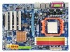
GA-M61P-S3 Motherboard Layout KB_MS Socket AM2 ATX COMA LPT VGA 1394 USB ATX_12V LAN USB AUDIO CPU_FAN F_AUDIO GA-M61P-S3 Realtek 8211 PCIE_1 PCIE_2 CODEC CD_IN SPDIF_IO DDRII_1 DDRII_2 DDRII_3 DDRII_4 IDE PCIE_16 BIOS BATTERY CLR_CMOS nVIDIA® PCI1 GeForce 6100/ nForce - Gigabyte GA-M61P-S3 | Manual - Page 8
(100 MHz) VGA AMD Socket AM2 CPU CPU CLK+/-(200 MHz) DDRII 800/667/533/400 MHz DIMM Dual Channel Memory Hyper Transport Bus PCI Express x16 LAN RJ45 PCI Express x1 Bus x1 x1 PCIe CLK (100 MHz) 1 PCI Express x2 RTL8211 PCI Bus TSB43AB23 4 SATA 3Gb/s nVIDIA® GeForce 6100/ nForce 430 LPC BUS - Gigabyte GA-M61P-S3 | Manual - Page 9
the instructions below: 1. Please turn off the computer and unplug its power cord. 2. When handling the motherboard, avoid touching any metal leads or connectors. 3. It is best to wear an electrostatic discharge (ESD) cuff when handling electronic components (CPU, RAM). 4. Prior to installing the - Gigabyte GA-M61P-S3 | Manual - Page 10
Summary CPU Š Socket AM2 for AMD AthlonTM 64 FX / AthlonTM 64 X2 Dual-Core / AthlonTM 64 / SempronTM processor Front Side Bus Š 2000 MHz Chipset Š nVIDIA® GeForce 6100/nForce 430 chipset LAN Š Realtek RTL8211 (10/100/1000 Mbit) Audio Š Onboard Realtek ALC883 CODEC chip Š Supports High - Gigabyte GA-M61P-S3 | Manual - Page 11
Install Š Supports Xpress Recovery2 Š Supports Xpress BIOS Rescue Bundle Software Š Norton Internet Security (OEM version) Form Factor Š Micro ATX form factor; 30.5cm x 21.5cm (Note 1) Due to the limitation of Windows 32-bit operating system, when more than 4 GB of physical memory is installed - Gigabyte GA-M61P-S3 | Manual - Page 12
finger down on the middle of the CPU and gently press the metal lever back into its original position. Please use extra care when installing the CPU. The CPU will not fit if positioned incorrectly. Rather than applying force, please change the positioning of the CPU. GA-M61P-S3 Motherboard - 12 - - Gigabyte GA-M61P-S3 | Manual - Page 13
paste on the surface of the CPU. Install all the CPU cooler components (Please refer to the cooler manual for detailed installation instructions). Fig.2 Please connect the CPU cooler power connector to the CPU_FAN connector located on the motherboard so that the CPU cooler can properly function to - Gigabyte GA-M61P-S3 | Manual - Page 14
only fit in one direction. Insert the DIMM memory module vertically into the DIMM socket. Then push it down. Fig.2 Close the plastic clip at both edges of the DIMM sockets to lock the DIMM module. Reverse the installation steps when you wish to remove the DIMM module. GA-M61P-S3 Motherboard - 14 - - Gigabyte GA-M61P-S3 | Manual - Page 15
English Dual Channel Memory Configuration The GA-M61P-S3 supports the Dual Channel Technology. After operating the Dual Channel Technology, the bandwidth of Memory Bus will double. Due to CPU limitation, if you wish to operate the Dual Channel Technology, follow the guidelines below: 1. Dual - Gigabyte GA-M61P-S3 | Manual - Page 16
onboard PCI Express x16 slot and press firmly down on the slot. Make sure your VGA card is locked by the latch at the end of the PCI Express x16 slot. When you try uninstall the VGA card, please press the latch as the picture to the left shows to release the card. GA-M61P-S3 Motherboard - 16 - Gigabyte GA-M61P-S3 | Manual - Page 17
USB controller. If your OS does not support USB controller, please contact OS vendor for possible patch or driver upgrade. For more information please contact your OS or device(s) vendors. LAN Port The provided Internet connection is Gigabit Ethernet, providing data transfer speeds of 10/100 - Gigabyte GA-M61P-S3 | Manual - Page 18
to the 2-/4-/6-/8- channel audio setup steps for detailed software configuration information. 1-7 Connectors Introduction 1 3 10 18 17 11 12 16 15 1) ATX_12V 2) ATX (Power Connector) 3) CPU_FAN 4) SYS_FAN 5) IDE 6) FDD 7) SATAII0 / 1 / 2 / 3 8) PWR_LED 9) F_PANEL GA-M61P-S3 Motherboard 2 5 7 13 - Gigabyte GA-M61P-S3 | Manual - Page 19
installed. Align the power connector with its proper location on the motherboard and connect tightly. The ATX_12V power connector mainly supplies power to the CPU. Power Good 5V SB(stand by +5V) +12V +12V(Only for 24-pin ATX) 3.3V(Only for 24-pin ATX) Pin No. 13 14 15 16 17 18 19 20 21 22 23 24 - Gigabyte GA-M61P-S3 | Manual - Page 20
GND). Remember to connect the CPU/system fan cable to the CPU_FAN/SYS_FAN connector to prevent CPU damage or system hanging caused by instructions located on the IDE device). Before attaching the IDE cable, please take note of the foolproof groove in the IDE connector. 40 39 GA-M61P-S3 Motherboard - Gigabyte GA-M61P-S3 | Manual - Page 21
the cable connects to the FDD drive. The types of FDD drives supported are: 360 KB, 720 KB, 1.2 MB, 1.44 MB and can provide up to 300 MB/s transfer rate. Please refer to the BIOS setting for the SATA 3Gb/s and install the proper driver in order to work properly. 1 SATAII3 7 1 SATAII1 7 7 SATAII2 - Gigabyte GA-M61P-S3 | Manual - Page 22
Blue) SPEAK (Speaker Connector) (Amber) RES (Reset Switch) (Green) PW (Power Switch) (Red) MSG (Message LED/Power/Sleep LED) (Yellow) NC ( Purple) GA-M61P-S3 Motherboard Reset Switch IDE Hard Disk Active LED Pin 1: LED anode(+) Pin 2: LED cathode(-) Pin 1: Power Pin 2- Pin 3: NC Pin 4: Data(-) Open - Gigabyte GA-M61P-S3 | Manual - Page 23
Power 4 NC 5 Line Out (R) 6 NC 7 NC 8 No Pin 9 Line Out (L) 10 NC By default, the audio driver is configured to support HD Audio. To connect an AC97 front panel audio module to this connector, please refer to the instructions on Page 76 about the software settings. - 23 - Hardware - Gigabyte GA-M61P-S3 | Manual - Page 24
-R 12) SPDIF_IO (S/PDIF In/Out Connector) The S/PDIF output is capable of providing digital audio to external speakers or compressed AC3 data to an external Dolby Digital Decoder. Use this feature 6 Pin No. 1 2 3 4 5 6 Definition Power No Pin SPDIF SPDIFI GND GND GA-M61P-S3 Motherboard - 24 - - Gigabyte GA-M61P-S3 | Manual - Page 25
, please contact your local dealer. Pin No. Definition 1 TPA+ 2 TPA- 3 GND 2 10 4 GND 1 9 5 TPB+ 6 TPB- 7 Power (12V) 8 Power (12V) 9 No Pin 10 GND - 25 - Hardware Installation - Gigabyte GA-M61P-S3 | Manual - Page 26
Intrusion, Case Open) This 2-pin connector allows your system to detect if the chassis cover is removed. You can check the "Case Opened" status in BIOS Setup. 1 Pin No. Definition 1 Signal 2 GND GA-M61P-S3 Motherboard - 26 - - Gigabyte GA-M61P-S3 | Manual - Page 27
type recommended by the manufacturer. Dispose of used batteries according to the manufacturer's instructions. If you want to erase CMOS... 1. Turn off the computer and unplug short for five seconds.) 3. Re-install the battery. 4. Plug the power cord in and turn on the computer. - 27 - Hardware - Gigabyte GA-M61P-S3 | Manual - Page 28
English GA-M61P-S3 Motherboard - 28 - - Gigabyte GA-M61P-S3 | Manual - Page 29
during the BIOS POST (Power-On Self Test) will take you to the CMOS SETUP screen. You can enter the BIOS setup screen by pressing "Ctrl + F1". If you wish to upgrade to a new BIOS, either Gigabyte's Q-Flash or @BIOS utility can be used. Q-Flash allows the user to quickly and easily update or backup - Gigabyte GA-M61P-S3 | Manual - Page 30
the BIOS Setup when somehow the system is not stable as usual. This action makes the system reset to the default settings for stability. 3. The BIOS Setup menus described in this chapter are for reference only and may differ from the exact settings for your motherboard. GA-M61P-S3 Motherboard - 30 - Gigabyte GA-M61P-S3 | Manual - Page 31
PCI & PnP ISA resources. „ PC Health Status This setup page is about system autodetect temperature, voltage, fan speed, etc. „ MB Intelligent Tweaker (M.I.T.) This setup page is to control CPU the system and Setup, or just to Setup. „ Set User Password Change, set, or disable password. It allows you - Gigabyte GA-M61P-S3 | Manual - Page 32
None] [None] [None] Drive A Floppy 3 Mode Support [1.44M, 3.5"] [Disabled] Halt On [All, But Keyboard] Base Memory Extended Memory 640K 447M KLJI: Move Enter: Select F5: Previous • Auto Allows BIOS to automatically detect IDE/SATA devices during POST. (default) GA-M61P-S3 Motherboard - 32 - - Gigabyte GA-M61P-S3 | Manual - Page 33
memory installed on the motherboard, or 640K for systems with 640K or more memory installed on the motherboard. Extended Memory The BIOS determines how much extended memory is present during the POST. This is the amount of memory located above 1 MB in the CPU's memory address map. - 33 - BIOS - Gigabyte GA-M61P-S3 | Manual - Page 34
BIOS Features AMD K8 AMD Cool&Quiet driver manages clock and VID to best serve the thermal, performance and power requirements. (Default value) Disabled Disable this function. Hard Disk Boot Priority Select boot sequence for onboard(or add-on cards) SCSI, RAID GA-M61P-S3 Motherboard - 34 - - Gigabyte GA-M61P-S3 | Manual - Page 35
Away Mode in Windows XP Media Center install a PCI card and a PCI Express VGA card on the motherboard. PCI Slot Set Init Display First to PCI user to decide when to activate the onboard VGA function. Enable If No Ext PEG Activate the onboard VGA first only when no PCI Express VGA card is installed - Gigabyte GA-M61P-S3 | Manual - Page 36
first channel of the first SATA 3Gb/s controller. (Default value) Disabled Disable this function. NV SATA 1 Secondary RAID Enabled Enable RAID function for the second channel of the first SATA 3Gb/s controller. Disabled (Default value) Disable this function. GA-M61P-S3 Motherboard - 36 - - Gigabyte GA-M61P-S3 | Manual - Page 37
USB memory type to base memory(640K). Onboard Audio Function Auto Auto detect Azalia audio function. (Default value) Disabled Disable Azalia audio function. Onboard 1394 Enabled Enable onboard IEEE 1394 function. (Default value) Disabled Disable onboard IEEE 1394 function. - 37 - BIOS - Gigabyte GA-M61P-S3 | Manual - Page 38
operate at a normal speed of 10/100/1000 Mbps in Windows mode or when the LAN Boot ROM is activated. When a Cable Problem Occurs... If a cable problem occurs on a specified pair of wires, the Status field shown is the approximate length of the attached LAN cable. GA-M61P-S3 Motherboard - 38 - - Gigabyte GA-M61P-S3 | Manual - Page 39
USB V1.1+V2.0 V1.1 Disabled Enable the USB 1.1 and USB 2.0 controllers. (Default value) Enable only the USB 1.1 controller. Disable the onboard USB controller. USB Keyboard Support Enabled Disabled Enable USB keyboard support. Disable USB keyboard support. (Default value) - 39 - BIOS Setup - Gigabyte GA-M61P-S3 | Manual - Page 40
An incoming call via modem can awake the system from any suspend state. Disabled Disable this function. Enabled Enable Modem Ring On function. (Default value) GA-M61P-S3 Motherboard - 40 - - Gigabyte GA-M61P-S3 | Manual - Page 41
, the system will be in "Off" state. Full-On (Default value) When AC-power back to the system, the system always in "On" state. - 41 - BIOS Setup - Gigabyte GA-M61P-S3 | Manual - Page 42
14,15 to PCI 1. Auto assign IRQ to PCI 2. (Default value) Set IRQ 3,4,5,7,9,10,11,12,14,15 to PCI 2. Auto assign IRQ to PCI 3. (Default value) Set IRQ 3,4,5,7,9,10,11,12,14,15 to PCI 3. Auto assign IRQ to PCI 4. (Default value) Set IRQ 3,4,5,7,9,10,11,12,14,15 to PCI 4. GA-M61P-S3 Motherboard - 42 - Gigabyte GA-M61P-S3 | Manual - Page 43
/ 176oF. 90oC / 194oF Monitor system/CPU temperature at 90oC / 194oF. Disabled Disable this function. (Default value) CPU/SYSTEM FAN Fail Warning Disabled Disable CPU/system fan fail warning function. (Default value) Enabled Enable CPU/system fan fail warning function. - 43 - BIOS Setup - Gigabyte GA-M61P-S3 | Manual - Page 44
is enabled, system fan will run at different speed depend- ing on system temperature. Users can adjust the fan speed with Easy Tune based on their requirements. (Note) Whether the CPU Smart FAN Control function is supported will depend on the CPU you install. GA-M61P-S3 Motherboard - 44 - - Gigabyte GA-M61P-S3 | Manual - Page 45
F1: General Help F7: Optimized Defaults Incorrectly using these features may result in system instability or corruption. Doing a overclock or overvoltage on CPU, chipsets and memory modules may result in damages or shortened life expectancy to these components. Please be aware that the M.I.T. menu - Gigabyte GA-M61P-S3 | Manual - Page 46
overclocking your system through the increase of the CPU voltage, damage to the CPU or decrease in the CPU life expectancy may occur. Supports adjustable CPU voltage from 0.8000V to 1.5500V. (Default value: Normal) Normal CPU Vcore Displays your CPU's normal vcore voltage. GA-M61P-S3 Motherboard - Gigabyte GA-M61P-S3 | Manual - Page 47
Peripherals Set Supervisor Password ` Power Management Setup ` PnP/PCI Configurations Set User Password Load Optimized DefaultSs a(vYe/N&)?ENxit Setup ` PC Health Defaults Selecting this field loads the factory defaults for BIOS and Chipset Features which the system automatically detects. - 47 - Gigabyte GA-M61P-S3 | Manual - Page 48
Advance BIOS Features Menu, you will be prompted for the password every time the system is rebooted or any time you try to enter Setup Menu. If you select "Setup" at "Password Check" in Advance BIOS Features Menu, you will be prompted only when you try to enter Setup. GA-M61P-S3 Motherboard - 48 - Gigabyte GA-M61P-S3 | Manual - Page 49
2-12 Exit Without Saving CMOS Setup Utility-Copyright (C) 1984-2006 Award Software ` Standard CMOS Features ` Advanced BIOS Features ` Integrated Peripherals ` Power Management Setup ` PnP/PCI Configurations ` PC Health Status ` MB Intelligent Tweaker(M.I.T.) Esc: Quit F8: Q-Flash Load Fail-Safe - Gigabyte GA-M61P-S3 | Manual - Page 50
English GA-M61P-S3 Motherboard - 50 - - Gigabyte GA-M61P-S3 | Manual - Page 51
shown in Windows XP. Insert the driver CD-title that came with your motherboard into your CD-ROM drive, the driver CD-title will auto start and show the installation guide. If not, please double click the CD-ROM device icon in "My computer", and execute the Run.exe. 3-1 Install Chipset Drivers After - Gigabyte GA-M61P-S3 | Manual - Page 52
Software Applications This page displays all the tools that Gigabyte developed and some free software, you can choose anyone you want and press "install" to install them. 3-3 Driver CD Information This page lists the contents of software and drivers in this CD-title. GA-M61P-S3 Motherboard - 52 - - Gigabyte GA-M61P-S3 | Manual - Page 53
English 3-4 Hardware Information This page lists all device you have for this motherboard. 3-5 Contact Us Please see the last page for details. - 53 - Drivers Installation - Gigabyte GA-M61P-S3 | Manual - Page 54
English GA-M61P-S3 Motherboard - 54 - - Gigabyte GA-M61P-S3 | Manual - Page 55
enhancement for CPU and Memory, 3) Smart-Fan control for managing fan speed control of both CPU cooling fan and North-Bridge Chipset cooling fan, 4) PC health for monitoring system status.(Note) User Interface Overview Button / Display Description 1. Overclocking Enters the Overclocking setting - Gigabyte GA-M61P-S3 | Manual - Page 56
hard disk data. Supporting Microsoft operating systems including Windows XP/2000/NT/98 2. At least 64M bytes of system memory 3. VESA-supported VGA cards How to use the Xpress installed once you complete installations of OS and all required drivers as well as software. GA-M61P-S3 Motherboard - 56 - - Gigabyte GA-M61P-S3 | Manual - Page 57
the driver CD before data backup. 2. It is normal that data backup takes longer time than data restoration. 3. Xpress Recovery2 is compliant with the GPL regulations. 4. On a few motherboards based on Nvidia chipsets, BIOS update is required for Xpress Recovery2 to correctly identify RAID and - Gigabyte GA-M61P-S3 | Manual - Page 58
Update BIOS from Drive Sa0vefilBeI(Os)SfotounDdrive EnteFr l:oRppuyn A :Move ESC:Reset :Power Off HDD 0-0 Total size : 0 F5 : Refresh Free size : 0 DEL : Delete c. Select the BIOS file and press ENTER. Make sure again the BIOS file matches your motherboard model. GA-M61P - Gigabyte GA-M61P-S3 | Manual - Page 59
the system reboots, you will see the new BIOS version during POST. Step 5: As the system reboots, press DELETE to enter BIOS Setup. Select Load Optimized Defaults and press ENTER to load BIOS defaults. System will re-detect all peripherals devices after BIOS update, so we recommend that you reload - Gigabyte GA-M61P-S3 | Manual - Page 60
Update" icon b. Click "Update New BIOS" c. Please select "All Files" in dialog box while opening the old file. d. Please search for BIOS unzip file, downloading from internet or any other methods (such as: M61PS3.F1). e. Complete update process following the instruction. GA-M61P-S3 Motherboard - Gigabyte GA-M61P-S3 | Manual - Page 61
unzip file are the same as your motherboard's. Otherwise, your system won't boot. III. In method I, if the BIOS file you need cannot be found in @BIOSTM server, please go onto Gigabyte's web site for downloading and updating it according to method II. IV. Please note that any interruption during - Gigabyte GA-M61P-S3 | Manual - Page 62
one end of the SATA signal cable to the rear of the SATA hard drive and the other end to available SATA port(s) on the motherboard. Then connect the power connector from your power supply to the hard drive. (Note) Required for setting up RAID array. GA-M61P-S3 Motherboard - 62 - - Gigabyte GA-M61P-S3 | Manual - Page 63
). In BIOS Setup, go to Integrated Periperals --> Serial-ATA RAID Config (Figure 1). CMOS Setup Utility-Copyright (C) 1984-2006 Award Software Integrated Peripherals Serial-ATA RAID Config On-Chip IDE Channel0 On-Chip MAC Lan NV Serial-ATA Controller IDE Prefetch Mode USB Memory Type Onboard Audio - Gigabyte GA-M61P-S3 | Manual - Page 64
] [Disabled] [PCI Slot] [64M] [Enable If No Ext PEG] Item Help Menu Level : Move Enter: Select F5: Previous Values +/-/PU/PD: Value F10: Save F6: Fail-Safe Defaults Figure 3 ESC: Exit F1: General Help F7: Optimized Defaults Step 3: Save and exit BIOS Setup. GA-M61P-S3 Motherboard - 64 - - Gigabyte GA-M61P-S3 | Manual - Page 65
Step 1: After the POST memory test begins and before the operating system boot begins, look for a message which says "Press F10 to enter RAID setup utility" (Figure 4). Hit the F10 key to enter the RAID BIOS setup utility. MediaShield ROM BIOS 6.87 Copyright (C) 2006 NVIDIA Corp. Detecting array - Gigabyte GA-M61P-S3 | Manual - Page 66
The Free Disks section displays the information about the currently installed SATA hard drives. Press the TAB key to move to the hard drives to the Array Disks section (Figure 6). RAID Mode: Striping MediaShield Utility Aug 21 2006 - Define a [ENTER] Popup Figure 7 GA-M61P-S3 Motherboard - 66 - - Gigabyte GA-M61P-S3 | Manual - Page 67
BIOS.) Boot BBS MediaShield Utility Aug 21 2006 - Array List - Status Vendor Array Model Name Healthy NVIDIA STRIPE 223.57G [Ctrl-X] Exit [ ] Select [B] Set Boot [N] New Array [ENTER] Detail Figure 8 To read more information about the RAID Nvidia RAID utility, press ESC in the main menu - Gigabyte GA-M61P-S3 | Manual - Page 68
users without a startup disk: Use an alternative system and insert the GIGABYTE motherboard driver CD-ROM. From the CD-ROM drive folder, double click the MENU.exe file in the BootDrv folder (Figure 12). A command prompt window will open similar to that in Figure 11. GA-M61P-S3 Motherboard Figure - Gigabyte GA-M61P-S3 | Manual - Page 69
SCSI or RAID driver. Figure 13 Step 2: When a screen similar to that below appears, insert the floppy disk containing the SATA driver and press S (Figure 14). Windows Setup Setup could not determine the type of one or more mass storage devices installed in your system, or you have chosen to manually - Gigabyte GA-M61P-S3 | Manual - Page 70
devices for use with Windows, press ENTER. S=Specify Additional Device Enter=Continue F3=Exit Figure 16 If a message appears saying one or some file(s) cannot be found, please check the floppy disk or copy the correct SATA driver again from the motherboard driver CD. GA-M61P-S3 Motherboard - 70 - - Gigabyte GA-M61P-S3 | Manual - Page 71
screen (Figure 17) appears, press ENTER to continue the SATA driver installation from the floppy disk. Windows Setup Setup will load support for the following mass storage device(s): NVIDIA RAID CLASS DRIVER (required) NVIDIA nForce Storage Controller (required) * To specify additional SCSI adapters - Gigabyte GA-M61P-S3 | Manual - Page 72
the best sound effect if the stereo output is applied. STEP 1 : After installation of the audio driver, you should find an Audio Manager icon in your system tray (you can also find the icon in Control Panel). Doubleclick the icon to open the Audio Control Panel. GA-M61P-S3 Motherboard - 72 - - Gigabyte GA-M61P-S3 | Manual - Page 73
Line Out jack, a small window will pop up and ask you what type of equipment is connected. Choose Headphone or Line Out depending on the device connected and click OK. The 2-channel audio setup is completed. 4 Channel Audio Setup STEP 1 : After installation of the audio driver, you should find an - Gigabyte GA-M61P-S3 | Manual - Page 74
audio setup is completed. 6 Channel Audio Setup STEP 1 : After installation of the audio driver, you should find an Audio audio consists of Front Speaker Out (Line Out), Rear Speaker Out, and Center/Subwoofer Speaker Out) then click OK. The 6-channel audio setup is completed. GA-M61P-S3 Motherboard - Gigabyte GA-M61P-S3 | Manual - Page 75
in Control Panel). Doubleclick the icon to open the Audio Control Panel. STEP 2: In the Audio Control Panel, click the Audio I/O tab. In the upper left list, click 8CH Speaker. STEP 3: After plugging in 8-channel speakers to the rear speaker jacks, a small window will pop up and ask you what type of - Gigabyte GA-M61P-S3 | Manual - Page 76
panel audio connector to support AC97 Audio mode, go to the Audio Control Panel and click the Audio I/O tab. In the ANALOG area, click the Tool icon and then select the Disable front panel jack detection check box. This action completes the AC'97 Audio configuration. GA-M61P-S3 Motherboard - 76 - Gigabyte GA-M61P-S3 | Manual - Page 77
English 4-2 Troubleshooting Below is a collection of general asked questions. To check general asked questions based on a specific motherboard model, please log on to http://www.gigabyte.com.tw Question 1: I cannot see some options that were included in previous BIOS after updating BIOS. Why? - Gigabyte GA-M61P-S3 | Manual - Page 78
. 814 Xian TEL: +86-29-85531943 FAX: +86-29-85539821 Shenyang TEL: +86-24-83992901 FAX: +86-24-83992909 y India GIGABYTE TECHNOLOGY (INDIA) LIMITED WEB address : http://www.gigabyte.in y Australia GIGABYTE TECHNOLOGY PTY. LTD. WEB address : http://www.gigabyte.com.au GA-M61P-S3 Motherboard - 78 - - Gigabyte GA-M61P-S3 | Manual - Page 79
BYTE Technology Co., Ltd. in SERBIA & MONTENEGRO WEB address : http://www.gigabyte.co.yu y GIGABYTE Global Service System To submit a technical or non-technical (Sales/ Marketing) question, please link to : http://ggts.gigabyte.com.tw Then select your language to enter the system. - 79 - Appendix - Gigabyte GA-M61P-S3 | Manual - Page 80
- 80 -
-
 1
1 -
 2
2 -
 3
3 -
 4
4 -
 5
5 -
 6
6 -
 7
7 -
8
-
9
-
10
-
11
-
12
-
13
-
14
-
15
-
16
-
17
-
18
-
19
-
20
-
21
-
22
-
23
-
24
-
25
-
26
-
27
-
28
-
29
-
30
-
31
-
32
-
33
-
34
-
35
-
36
-
37
-
38
-
39
-
40
-
41
-
42
-
43
-
44
-
45
-
46
-
47
-
48
-
49
-
50
-
51
-
52
-
53
-
54
-
55
-
56
-
57
-
58
-
59
-
60
-
61
-
62
-
63
-
64
-
65
-
66
-
67
-
68
-
69
-
70
-
71
-
72
-
73
-
74
-
75
-
76
-
77
-
78
-
79
-
80
 |
 |

GA-M61P-S3
AMD Socket AM2 Processor Motherboard
User's Manual
Rev. 100
2
12ME-M61PS3-100
2
R
*
The WEEE marking on the product indicates this product must not be disposed of with user's other household waste
and must be handed over to a designated collection point for the recycling of waste electrical and electronic equipment!!
*
The WEEE marking applies only in European Union's member states.