Gigabyte GA-M61PME-S2P Manual
Gigabyte GA-M61PME-S2P Manual
 |
UPC - 818313005199
View all Gigabyte GA-M61PME-S2P manuals
Add to My Manuals
Save this manual to your list of manuals |
Gigabyte GA-M61PME-S2P manual content summary:
- Gigabyte GA-M61PME-S2P | Manual - Page 1
GA-M61PME-S2P AM2+/AM2 socket motherboard for AMD PhenomTM FX processor/AMD PhenomTM X4 processor/ AMD PhenomTM X3 processor/AMD AthlonTM X2 processor/ AMD AthlonTM processor/AMD SempronTM X2 processor/ AMD SempronTM processor User's Manual Rev. 1002 12ME-M61PMEP2-1002R - Gigabyte GA-M61PME-S2P | Manual - Page 2
Motherboard GA-M61PME-S2P Jan. 8, 2009 Motherboard GA-M61PME-S2P Jan. 8, 2009 -2- - Gigabyte GA-M61PME-S2P | Manual - Page 3
of documentations: For detailed product information, carefully read the User's Manual. For instructions on how to use GIGABYTE's unique features, read or download the information on/from the Support\Motherboard\Technology Guide page on our website. For product-related information, check on our - Gigabyte GA-M61PME-S2P | Manual - Page 4
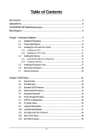
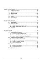
Box Contents ...6 OptionalItems ...6 GA-M61PME-S2P Motherboard Layout 7 Block Diagram ...8 Chapter 1 Hardware Installation 9 1-1 Installation Precautions 9 1-2 Product Specifications 10 1-3 Installing the CPU and CPU Cooler 12 1-3-1 Installing the CPU 12 1-3-2 Installing the CPU Cooler 14 - Gigabyte GA-M61PME-S2P | Manual - Page 5
Chipset Drivers 51 3-2 Application Software 52 3-3 Technical Manuals 52 3-4 Contact ...53 3-5 System ...53 3-6 Download Center 54 Chapter 4 Unique Features 55 4-1 Xpress Recovery2 55 4-2 BIOS Update Utilities 58 4-2-1 Updating the BIOS with the Q-Flash Utility 58 4-2-2 Updating the BIOS with - Gigabyte GA-M61PME-S2P | Manual - Page 6
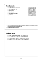
GA-M61PME-S2P motherboard Motherboard driver disk User's Manual One IDE cable One SATA 3Gb/s cables I/O Shield • The box contents above are for reference only and the actual items shall depend on product package you obtain. The box contents are subject to change without notice. • The motherboard - Gigabyte GA-M61PME-S2P | Manual - Page 7
GA-M61PME-S2P Motherboard Layout KB_MS ATX_12V Socket AM2 ATX VGA COMA LPT R_USB CPU_FAN USB LAN IT8718 AUDIO F_AUDIO CI M_BIOS B_BIOS HDA_SUR PCIEX1 Realtek 8201CL PCI1 GA-M61PME-S2P PCIEX16 CLR_CMOS BAT CD_IN PCI2 IDE DDR2_1 DDR2_2 SATA2_0 NVIDIA® GeForce 6100/ nForce 430 - Gigabyte GA-M61PME-S2P | Manual - Page 8
Express x1 LAN RJ45 Realtek 8201CL PCI Bus AMD Socket AM2+/AM2 CPU CPU CLK+/-(200 MHz) DDR2 1066/800/667 MHz DIMM Dual Channel Memory Hyper Transport Bus D-Sub NVIDIA® GeForce 6100/ nForce 430 8 USB Ports 2 SATA 3Gb/s ATA-133/100/66/33 IDE Channel CODEC LPC BUS IT8718 Dual BIOS Floppy LPT - Gigabyte GA-M61PME-S2P | Manual - Page 9
manual and follow these procedures: • Prior to installation, do not remove or break motherboard components such as a motherboard, CPU or memory. If you power supply cable from the motherboard, make sure the power supply has been turned off. • Before turning on the power, make sure the power supply - Gigabyte GA-M61PME-S2P | Manual - Page 10
24-pin ATX main power connector 1 x 4-pin ATX 12V power connector 1 x floppy disk drive connector 1 x IDE connector 2 x SATA 3Gb/s connectors 1 x CPU fan header 1 x system fan header 1 x front panel header 1 x front panel audio header 1 x surround/center audio header GA-M61PME-S2P Motherboard - 10 - Gigabyte GA-M61PME-S2P | Manual - Page 11
Dual BIOS Support for Download Center Support for Xpress Install Support for Xpress Recovery2 Support for EasyTune (Note 4) Bundled Software Norton Internet Security (OEM version) Operating System Support for Microsoft® Windows® Vista/XP Form Factor Micro ATX Form Factor - Gigabyte GA-M61PME-S2P | Manual - Page 12
card, memory, hard drive, etc. 1-3-1 Installing the CPU A. Locate the pin one (denoted by a small triangle) of the CPU socket and the CPU. A Small Triangle Mark Denotes Pin One of the Socket AM2 Socket A Small Triangle Marking Denotes CPU Pin One AM2+/AM2 CPU GA-M61PME-S2P Motherboard - 12 - - Gigabyte GA-M61PME-S2P | Manual - Page 13
below to correctly install the CPU into the motherboard CPU socket. Before installing the CPU, make sure to turn off the computer and unplug the power cord from the power outlet to prevent damage to the CPU. CPU Socket Locking Lever Step 1: Completely lift up the CPU socket locking lever. Step - Gigabyte GA-M61PME-S2P | Manual - Page 14
the power connector of the CPU cooler to the CPU fan header (CPU_FAN) on the motherboard. Use extreme care when removing the CPU cooler because the thermal grease/tape between the CPU cooler and CPU may adhere to the CPU. Inadequately removing the CPU cooler may damage the CPU. GA-M61PME-S2P - Gigabyte GA-M61PME-S2P | Manual - Page 15
memory, switch the direction. 1-4-1 Dual Channel Memory Configuration This motherboard provides two DDR2 memory sockets and supports Dual Channel Technology. After the memory is installed, the BIOS will automatically detect the specifications and capacity of the memory. Enabling Dual Channel memory - Gigabyte GA-M61PME-S2P | Manual - Page 16
the computer and unplug the power cord from the power outlet to prevent damage to the memory module. DDR2 DIMMs are not compatible to DDR DIMMs. Be sure to install DDR2 DIMMs on this motherboard. Notch DDR2 DIMM A place when the memory module is securely inserted. GA-M61PME-S2P Motherboard - 16 - - Gigabyte GA-M61PME-S2P | Manual - Page 17
motherboard supports the expansion card. Carefully read the manual that came with your expansion card. • Always turn off the computer and unplug the power cord from the power , go to BIOS Setup to make any required BIOS changes for your expansion card(s). 7. Install the driver provided with the - Gigabyte GA-M61PME-S2P | Manual - Page 18
. Connect a monitor that supports D-Sub connection to this port. USB Port The USB port supports the USB 2.0/1.1 specification. Use this port for USB devices such as an USB keyboard/mouse, USB printer, USB flash drive and etc. RJ-45 LAN Port The Fast Ethernet LAN port provides Internet connection - Gigabyte GA-M61PME-S2P | Manual - Page 19
to this jack. To configure 7.1-channel audio, you need to install a 5.1/7.1 surround cable (optional) and enable the multi-channel audio feature through the audio driver. Refer to the instructions on setting up a 2/4/5.1/7.1-channel audio configuration in Chapter 5, "Configuring 2/4/5.1/7.1Channel - Gigabyte GA-M61PME-S2P | Manual - Page 20
13 14 1) ATX_12V 2) ATX 3) CPU_FAN 4) SYS_FAN 5) power cord from the power outlet to prevent damage to the devices. • After installing the device and before turning on the computer, make sure the device cable has been securely attached to the connector on the motherboard. GA-M61PME-S2P Motherboard - Gigabyte GA-M61PME-S2P | Manual - Page 21
1/2) ATX_12V/ATX (2x2 12V Power Connector and 2x12 Main Power Connector) With the use of the power connector, the power supply can supply enough stable power to all the components on the motherboard. Before connecting the power connector, first make sure the power supply is turned off and all - Gigabyte GA-M61PME-S2P | Manual - Page 22
drives supported are: 360 KB, 720 KB, 1.2 MB, 1.44 MB, and 2.88 MB. Before connecting a floppy disk drive, be sure to locate pin 1 of the connector and the floppy disk drive cable. The pin 1 of the cable is typically designated by a stripe of different color. 33 1 34 2 GA-M61PME-S2P Motherboard - Gigabyte GA-M61PME-S2P | Manual - Page 23
with SATA 1.5Gb/s standard. Each SATA connector supports a single SATA device. The NVIDIA® GeForce 6100/ nForce 430 chipset controller supports RAID 0 and RAID 1. Refer to Chapter 5, "Configuring SATA Hard Drive(s)," for instructions on configuring a RAID array. SATA2_0 7 1 1 7 SATA2_1 Pin - Gigabyte GA-M61PME-S2P | Manual - Page 24
S0 On S1 Blinking S3/S4/S5 Off 9) BAT (BATTERY) The battery provides power to keep the values (such as BIOS configurations, date, and time information) in the CMOS when the computer is turned must be handled in accordance with local environmental regulations. GA-M61PME-S2P Motherboard - 24 - - Gigabyte GA-M61PME-S2P | Manual - Page 25
positive and negative pins before connecting the cables. Message/Power/ Power Sleep LED Switch Speaker MSG+ MSG- PW+ PWSPEAK problem is detected at system startup. If a problem is detected, the BIOS may issue beeps in different patterns to indicate the problem. Refer to Chapter 5, "Troubleshooting - Gigabyte GA-M61PME-S2P | Manual - Page 26
the audio software. For purchasing the optional 5.1/7.1 surround cable, please contact the local dealer. 2 14 1 13 Pin No. 1 2 3 4 5 6 7 8 9 10 11 12 13 14 Definition LEF_P SURR_RR CEN_P SURR_LL CEN_JD SURR_JD GND -SUR_DET GND No Pin GND S_SURR_JD S_SURR_LL S_SURR_RR GA-M61PME-S2P Motherboard - Gigabyte GA-M61PME-S2P | Manual - Page 27
an optional S/PDIF out cable, this header can connect to an audio device that supports digital audio in. For purchasing the optional S/PDIF out cable, please contact the local dealer. 51 62 Pin No. 1 2 3 4 5 6 Definition Power No Pin SPDIF SPDIFI GND GND Pin 1 (the red wire) of the S/PDIF out - Gigabyte GA-M61PME-S2P | Manual - Page 28
the USB bracket. 16) CI (Chassis Intrusion Header) This motherboard provides a chassis detection feature that detects if the chassis cover has been removed. This function requires a chassis with chassis intrusion detection design. Pin No. Definition 1 1 Signal 2 GND GA-M61PME-S2P Motherboard - Gigabyte GA-M61PME-S2P | Manual - Page 29
turn off your computer and unplug the power cord from the power outlet before clearing the CMOS values. • motherboard. • After system restart, go to BIOS Setup to load factory defaults (select Load Optimized Defaults) or manually configure the BIOS settings (refer to Chapter 2, "BIOS Setup," for BIOS - Gigabyte GA-M61PME-S2P | Manual - Page 30
GA-M61PME-S2P Motherboard - 30 - - Gigabyte GA-M61PME-S2P | Manual - Page 31
that searches and downloads the latest version of BIOS from the Internet and updates the BIOS. For instructions on using the Q-Flash and @BIOS utilities, refer to Chapter 4, "BIOS Update Utilities." • Because BIOS flashing is potentially risky, if you do not encounter problems using the current - Gigabyte GA-M61PME-S2P | Manual - Page 32
Startup Screen The following screen may appear when the computer boots. Motherboard Model BIOS Version Award Modular BIOS v6.00PG, An Energy Star Ally Copyright (C) 1984-2008, Award Software, Inc. GA-M61PME-S2P E8 . . . . : BIOS Setup : XpressRecovery2 : Boot Menu : Qflash 12/16 - Gigabyte GA-M61PME-S2P | Manual - Page 33
Version: E8) CMOS Setup Utility-Copyright (C) 1984-2008 Award Software Standard CMOS Features Advanced BIOS Features Integrated Peripherals Power Management Setup PnP/PCI Configurations PC Health Status Load Fail-Safe Defaults Load Optimized Defaults Set Supervisor Password Set User - Gigabyte GA-M61PME-S2P | Manual - Page 34
BIOS Features Use this menu to configure the device boot order, advanced features available on the CPU, and the primary display adapter. Integrated Peripherals Use this menu to configure all peripheral devices, such as IDE, SATA, USB, integrated audio, and integrated LAN, etc. Power Management - Gigabyte GA-M61PME-S2P | Manual - Page 35
Features Mon, Dec 15 2008 11:52:24 Item Help Menu Level IDE Drive A Floppy 3 Mode Support [1.44M, 3.5"] [Disabled] • Auto Lets BIOS automatically detect IDE/ Manual skip the detection of the device during the POST for faster system startup. Allows you to manually enter the specifications - Gigabyte GA-M61PME-S2P | Manual - Page 36
specifications. If you wish to enter the parameters manually Floppy 3 Mode Support Allows you to BIOS POST. Base Memory Also called conventional memory. Typically, 640 KB will be reserved for the MS-DOS operating system. Extended Memory The amount of extended memory. GA-M61PME-S2P Motherboard - Gigabyte GA-M61PME-S2P | Manual - Page 37
driver dynamically adjust the CPU clock and VIA to reduce heat output from your computer and its power up or down on the list. Press to USB-FDD, USB-ZIP, USB-CDROM, USB-HDD, Legacy LAN, Disabled. (Note) This item is present only if you install a CPU that supports this feature. - 37 - BIOS - Gigabyte GA-M61PME-S2P | Manual - Page 38
required for booting the system and for entering the BIOS Setup program. HDD S.M.A.R.T. Capability Enables or disables the XP Media Center operating system. Away Mode allows the system to silently perform unattended tasks while in a low-power mode Enable. GA-M61PME-S2P Motherboard - 38 - - Gigabyte GA-M61PME-S2P | Manual - Page 39
Onboard Audio Function On-Chip MAC Lan Onboard LAN Boot ROM Onboard Serial Port 1 Onboard Parallel Port Parallel Port Mode x ECP Mode Use DMA On-Chip USB USB Keyboard Support USB Mouse Support Legacy USB storage -Safe Defaults ESC: Exit F1: General Help F7: Optimized Defaults - 39 - BIOS Setup - Gigabyte GA-M61PME-S2P | Manual - Page 40
. V1.1+V2.0 Enables the integrated USB 1.1 and USB 2.0 controllers. (Default) V1.1 Disabled Enables only the integrated USB 1.1 controller. Disables the integrated USB 1.1 and USB 2.0 controllers. Disabled will turn off all of the USB functionalities below. GA-M61PME-S2P Motherboard - 40 - - Gigabyte GA-M61PME-S2P | Manual - Page 41
to be used in MS-DOS. (Default: Disabled) USB Mouse Support Allows USB mouse to be used in MS-DOS. (Default: Disabled) Legacy USB storage detect Determines whether to detect USB storage devices, including USB flash drives and USB hard drives during the POST. (Default: Enabled) - 41 - BIOS Setup - Gigabyte GA-M61PME-S2P | Manual - Page 42
RAM) sleep state. In S3 sleep state, the system appears to be off and consumes less power this function, you need an ATX power supply providing at least 1A on supports wake-up function. (Default: Enabled) (Note) Supported on Windows® Vista® operating system only. GA-M61PME-S2P Motherboard - 42 - - Gigabyte GA-M61PME-S2P | Manual - Page 43
USB device. (Default: Enabled) Power-On by Alarm Determines whether to power specific time on each day or on a specific day in a month. Time (hh: mm: ss) Alarm: Set the time at which the system will be powered you need an ATX power supply providing at least 1A need an ATX power supply providing at - Gigabyte GA-M61PME-S2P | Manual - Page 44
Help F7: Optimized Defaults BIOS auto-assigns IRQ to the first PCI slot. (Default) Assigns IRQ 3,4,5,7,9,10,11,12,14,15 to the first PCI slot. BIOS auto-assigns IRQ to the second PCI slot. (Default) Assigns IRQ 3,4,5,7,9,10,11,12,14,15 to the second PCI slot. GA-M61PME-S2P Motherboard - 44 - - Gigabyte GA-M61PME-S2P | Manual - Page 45
to the motherboard CI header CPU Temperature Displays current system/CPU temperature. Current CPU/SYSTEM FAN Speed (RPM) Displays current CPU/system fan speed. System/CPU Warning Temperature Sets the warning threshold for system/CPU temperature. When system/CPU temperature exceeds the threshold, BIOS - Gigabyte GA-M61PME-S2P | Manual - Page 46
configurable only if CPU Smart FAN Control is set to Enabled. Auto Lets BIOS autodetect the type of CPU fan installed and sets the optimal CPU fan control mode. (Default) Voltage Sets Voltage mode for a 3-pin CPU fan. PWM Sets PWM mode for a 4-pin CPU fan. GA-M61PME-S2P Motherboard - 46 - - Gigabyte GA-M61PME-S2P | Manual - Page 47
, which are the safest and most stable BIOS settings for the motherboard. 2-10 Load Optimized Defaults CMOS Setup Utility-Copyright (C) 1984-2008 Award Software Standard CMOS Features Advanced BIOS Features Integrated Peripherals Power Management Setup PnP/PCI Configurations PC Health - Gigabyte GA-M61PME-S2P | Manual - Page 48
you to view the BIOS settings but not to make changes. To clear the password, press on the password item and when requested for the password, press again. The message "PASSWORD DISABLED" will appear, indicating the password has been cancelled. GA-M61PME-S2P Motherboard - 48 - - Gigabyte GA-M61PME-S2P | Manual - Page 49
Setup Main Menu. 2-13 Exit Without Saving CMOS Setup Utility-Copyright (C) 1984-2008Award Software Standard CMOS Features Advanced BIOS Features Integrated Peripherals Power Management Setup PnP/PCI Configurations PC Health Status Esc: Quit F8: Q-Flash Load Fail-Safe Defaults Load - Gigabyte GA-M61PME-S2P | Manual - Page 50
GA-M61PME-S2P Motherboard - 50 - - Gigabyte GA-M61PME-S2P | Manual - Page 51
other drivers. • After the drivers are installed, follow the onscreen instructions to restart your system. You can install other applications included in the motherboard driver disk. • For USB 2.0 driver support under the Windows XP operating system, please install the Windows XP Service Pack - Gigabyte GA-M61PME-S2P | Manual - Page 52
and applications that GIGABYTE develops and some free software. You can click the Install button on the right of an item to install it. 3-3 Technical Manuals This page provides content descriptions for this driver disk and the motherboard manuals. GA-M61PME-S2P Motherboard - 52 - - Gigabyte GA-M61PME-S2P | Manual - Page 53
3-4 Contact For the detailed contact information of the GIGABYTE Taiwan headquarter or worldwide branch offices, click the URL on this page to link to the GIGABYTE Website. 3-5 System This page provides the basic system information. - 53 - Drivers Installation - Gigabyte GA-M61PME-S2P | Manual - Page 54
3-6 Download Center To update the BIOS, drivers, or applications, click the Download Center button to link to the GIGABYTE Web site. The latest version of the BIOS, drivers, or applications will be displayed. GA-M61PME-S2P Motherboard - 54 - - Gigabyte GA-M61PME-S2P | Manual - Page 55
up your system soon after the operating system and drivers are installed. • The amount of data and hard drive system memory • VESA compatible graphics card • Windows® XP with SP1 or later, Windows® Vista • Xpress USB hard drives are not supported. • Hard drives in RAID/AHCI mode are not supported - Gigabyte GA-M61PME-S2P | Manual - Page 56
Xpress Recovery2 cannot save the backup file. B. Accessing Xpress Recovery2 1. Boot from the motherboard driver disk to access Xpress Recovery2 for the first time. When you see the following message: 2: When finished, go to Disk Management to check disk allocation. GA-M61PME-S2P Motherboard - 56 - - Gigabyte GA-M61PME-S2P | Manual - Page 57
D. Using the Restore Function in Xpress Recovery2 Select RESTORE to restore the backup to your hard drive in case the system breaks down. The RESTORE option will not be present if no backup is created before. E. Removing the Backup Step 1: If you wish to remove the backup file, select REMOVE. F. - Gigabyte GA-M61PME-S2P | Manual - Page 58
and update the BIOS. 4-2-1 Updating the BIOS with the Q-Flash Utility A. Before You Begin: 1. From GIGABYTE's website, download the latest compressed BIOS update file that matches your motherboard model. 2. Extract the file and save the new BIOS file (e.g. M61PME2P.F1) to your floppy disk, USB flash - Gigabyte GA-M61PME-S2P | Manual - Page 59
HDD 0-0 Keep DMI Data Enable Update BIOS from Drive Sa0vefilBeI(Os)SfotounDdrive :Move ESC:Reset :Power Off Total size : 0 Free size : 0 3. Select the BIOS update file and press . Make sure the BIOS update file matches your motherboard model. Step 2: The process - Gigabyte GA-M61PME-S2P | Manual - Page 60
: Quit F8: Q-Flash Select Item F10: Save & Exit Setup Load Optimized Defaults Press to load BIOS defaults Step 6: Select Save & Exit Setup and then press to save settings to CMOS and exit BIOS Setup. The procedure is complete after the system restarts. GA-M61PME-S2P Motherboard - 60 - - Gigabyte GA-M61PME-S2P | Manual - Page 61
and Using @BIOS: Use the motherboard driver disk included with the motherboard to install @BIOS. • Installing the @BIOS utility. • Accessing the @BIOS utility. Select @BIOS and click Install. Click Start>All Programs>Gigabyte>@BIOS C. Options and Instructions: 1. Save the Current BIOS File In - Gigabyte GA-M61PME-S2P | Manual - Page 62
in an unbootable system. • If the BIOS update file for your motherboard is not present on the @BIOS server site, please manually download the BIOS update file from GIGABYTE's website and follow the instructions in "Update the BIOS without Using the Internet Update Function" below. Step 4: As the - Gigabyte GA-M61PME-S2P | Manual - Page 63
BIOS Setup program. EasyTune 5 provides the following functions (Note 1): overclocking/overvoltage, C.I.A./ M.I.B. (Note 2), smart fan control, and hardware monitoring and warning. (For instructions on using EasyTune5, read or download the information on/from the Support\Motherboard of CPU frequency - Gigabyte GA-M61PME-S2P | Manual - Page 64
GA-M61PME-S2P Motherboard - 64 - - Gigabyte GA-M61PME-S2P | Manual - Page 65
driver disk. 5-1-1 Configuring the Onboard SATA Controller A. Installing SATA hard drive(s) in your computer Attach one end of the SATA signal cable to the rear of the SATA hard drive and the other end to available SATA port on the motherboard. Then connect the power connector from your power supply - Gigabyte GA-M61PME-S2P | Manual - Page 66
2: Save changes and exit BIOS Setup. Figure 2 The BIOS Setup menus described in this section may differ from the exact settings for your motherboard. The actual BIOS Setup menu options you will see shall depend on the motherboard you have and the BIOS version. GA-M61PME-S2P Motherboard - 66 - - Gigabyte GA-M61PME-S2P | Manual - Page 67
to enter the NVIDIA RAID setup utility. MediaShield ROM BIOS 6.94 Copyright (C) 2006 NVIDIA Corp. Detecting array arrow key to select a RAID mode. The supported RAID modes include Mirroring, Striping, and Spanning. 0 (Striping) is selected, you can manually set the stripe block size. In the Striping - Gigabyte GA-M61PME-S2P | Manual - Page 68
d[Nisk] NdaO1ta.0?.M ST3120026AS [] Add 1.1.M ST3120026AS [Y] YES [N] NO [] Del Capacity 111.79GB 111.79GB [ESC] Quit [F6] Back [F7] Finish [TAB] Navigate [] Select [ENTER] Popup Figure 6 GA-M61PME-S2P Motherboard - 68 - - Gigabyte GA-M61PME-S2P | Manual - Page 69
have created (Figure 7). Boot No MediaShield Utility Nov 20 2006 - Array List - Status Vendor Array Model Name Healthy NVIDIA STRIPE 223.57G [Ctrl-X] to cancel. Press to return to the Array List screen. To exit the NVIDIA RAID setup utility, press in the main menu or - Gigabyte GA-M61PME-S2P | Manual - Page 70
users without a startup disk: Use an alternative system and insert the motherboard driver disk. From your optical drive folder, double click the MENU.exe file in the BootDrv folder (Figure 3). A command prompt window will open similar to that in Figure 2. GA-M61PME-S2P Motherboard Figure 3 - 70 - - Gigabyte GA-M61PME-S2P | Manual - Page 71
Adapter for use with Windows, using a device support disk provided by an adapter manufacturer. Select the SCSI Adapter you want from the following list, or press ESC to return to the previous screen. NVIDIA RAID Driver (required) NVIDIA nForce Storage Controller (required) ENTER=Select F3=Exit - Gigabyte GA-M61PME-S2P | Manual - Page 72
you want to manually rebuild a hard drive in the array. Step 1: In NVIDIA Control Panel, click Rebuild array under Storage in the Select a Task pane. Step 2: When the NVIDIA Rebuild Array Wizard appears, follow the on-screen instructions to complete the rebuilding. GA-M61PME-S2P Motherboard - 72 - Gigabyte GA-M61PME-S2P | Manual - Page 73
Channel Audio The motherboard provides three audio jacks on the back panel which can support 2/4/5.1-channel audio. To enable 7.1-channel audio, you need to install an additional 5.1/7.1 surround cable (optional) and enable the 7.1-channel audio function through the audio driver. A. Installing - Gigabyte GA-M61PME-S2P | Manual - Page 74
the HD Audio Manager. Before installing the audio driver, make sure the "Microsoft UAA Bus driver for High Definition Audio" has been installed from the motherboard driver disk and your operating system has been updated with the latest Service Pack for Windows. GA-M61PME-S2P Motherboard - 74 - Gigabyte GA-M61PME-S2P | Manual - Page 75
tab. In the Speaker Configuration list, select Stereo, Quadraphonic, 5.1 Speaker, or 7.1 Speaker according to the type of speaker configuration you wish to set up. Then the speaker setup is completed. C. Configuring Sound Effect: You may configure an audio environment on the Sound Effects tab - Gigabyte GA-M61PME-S2P | Manual - Page 76
1: First, attach the connector at the end of the cable to the SPDIF_IO header on your motherboard. Step 2: Secure the metal bracket to the chassis back panel with a screw. (Note) The actual locations of the SPDIF In and SPDIF Out connectors may differ by model. GA-M61PME-S2P Motherboard - 76 - - Gigabyte GA-M61PME-S2P | Manual - Page 77
Cable Step 3: Connect a S/PDIF coaxial cable or a S/PDIF optical cable (either one) to an external decoder for transmitting the S/PDIF digital audio signals. S/PDIF Optical Cable B. Configuring S/PDIF In and Out: B-1. Configuring S/PDIF In: On the Digital Input screen, click the Default Format - Gigabyte GA-M61PME-S2P | Manual - Page 78
Microphone Recording Step 1: After installing the audio driver, the HD Audio Manager icon will appear in the notification area. Doubleclick the icon to access the HD Audio Manager. Step 2: Connect your microphone -click on Microphone and select Set Default Device. GA-M61PME-S2P Motherboard - 78 - - Gigabyte GA-M61PME-S2P | Manual - Page 79
, click Start, point to All Programs, point to Accessories, and then click Sound Recorder to begin the sound recording. * Enabling Stereo Mix If the HD Audio Manager does not display the recording device you wish to use, refer to the steps below. The following steps explain how to enable Stereo Mix - Gigabyte GA-M61PME-S2P | Manual - Page 80
button . 3. To stop recording audio, click the Stop Recording button . Be sure to save the recorded audio file upon completion. B. Playing the Recorded Sound: You can play your recording in a digital media player program that supports your audio file format. GA-M61PME-S2P Motherboard - 80 - - Gigabyte GA-M61PME-S2P | Manual - Page 81
to clear the CMOS values. If your board doesn't have this jumper, refer to the instructions on the motherboard battery in Chapter 1. You can temporarily remove the battery from the battery holder to stop supplying power to the CMOS, which will clear the CMOS values after about one minute. Refer to - Gigabyte GA-M61PME-S2P | Manual - Page 82
insert the memory into the memory socket. The problem is verified and solved. Press to enter BIOS Setup. Select "Load Fail-Safe Defaults" (or "Load Optimized Defaults"). Select "Save & Exit Setup" to save changes and exit BIOS Setup. A (Continued...) GA-M61PME-S2P Motherboard - 82 - - Gigabyte GA-M61PME-S2P | Manual - Page 83
computer. No The power supply, CPU or CPU socket might fail. The problem is verified and solved. No The graphics card, expansion slot, or monitor might fail. The problem is verified and solved. Check if the keyboard is working properly. Yes Press to enter BIOS Setup. Select "Load - Gigabyte GA-M61PME-S2P | Manual - Page 84
please contact your local government office, your household waste disposal service or where you purchased the product for details of environmentally at the Customer Care number listed in your product's user's manual and we will be glad to help you with your effort. GA-M61PME-S2P Motherboard - 84 - - Gigabyte GA-M61PME-S2P | Manual - Page 85
that potentially hazardous substances are not released into the environment and are disposed of properly. China Restriction of Hazardous Substances Table The following table is supplied in compliance with China's Restriction of Hazardous Substances (China RoHS) requirements: - 85 - Appendix - Gigabyte GA-M61PME-S2P | Manual - Page 86
GA-M61PME-S2P Motherboard - 86 - - Gigabyte GA-M61PME-S2P | Manual - Page 87
CO., LTD. Address: No.6, Bau Chiang Road, Hsin-Tien, Taipei 231, Taiwan TEL: +886-2-8912-4000 FAX: +886-2-8912-4003 Tech. and Non-Tech. Support (Sales/Marketing) : http://ggts.gigabyte.com.tw WEB address (English): http://www.gigabyte.com.tw WEB address (Chinese): http://www.gigabyte.tw G.B.T. INC - Gigabyte GA-M61PME-S2P | Manual - Page 88
language in the language list on the top right corner of the website. GIGABYTE Global Service System To submit a technical or non-technical (Sales/ Marketing) question, please link to : http://ggts.gigabyte.com.tw Then select your language to enter the system. GA-M61PME-S2P Motherboard - 88 -
-
 1
1 -
 2
2 -
 3
3 -
 4
4 -
 5
5 -
 6
6 -
 7
7 -
8
-
9
-
10
-
11
-
12
-
13
-
14
-
15
-
16
-
17
-
18
-
19
-
20
-
21
-
22
-
23
-
24
-
25
-
26
-
27
-
28
-
29
-
30
-
31
-
32
-
33
-
34
-
35
-
36
-
37
-
38
-
39
-
40
-
41
-
42
-
43
-
44
-
45
-
46
-
47
-
48
-
49
-
50
-
51
-
52
-
53
-
54
-
55
-
56
-
57
-
58
-
59
-
60
-
61
-
62
-
63
-
64
-
65
-
66
-
67
-
68
-
69
-
70
-
71
-
72
-
73
-
74
-
75
-
76
-
77
-
78
-
79
-
80
-
81
-
82
-
83
-
84
-
85
-
86
-
87
-
88
 |
 |

GA-M61PME-S2P
AM2+/AM2 socket motherboard for
AMD Phenom
TM
FX processor/AMD Phenom
TM
X4 processor/
AMD Phenom
TM
X3 processor/AMD Athlon
TM
X2 processor/
AMD Athlon
TM
processor/AMD Sempron
TM
X2 processor/
AMD Sempron
TM
processor
User's Manual
Rev. 1002
12ME-M61PMEP2-1002R