Gigabyte GA-M68SM-S2L Manual
Gigabyte GA-M68SM-S2L Manual
 |
View all Gigabyte GA-M68SM-S2L manuals
Add to My Manuals
Save this manual to your list of manuals |
Gigabyte GA-M68SM-S2L manual content summary:
- Gigabyte GA-M68SM-S2L | Manual - Page 1
GA-M68SM-S2L AM2 socket motherboard for AMD AthlonTM 64 FX processor/ AMD AthlonTM 64 X2 Dual-Core processor/ AMD AthlonTM 64 processor/AMD SempronTM processor User's Manual Rev. 1003 12ME-M68SMS2L-1003R - Gigabyte GA-M68SM-S2L | Manual - Page 2
Motherboard GA-M68SM-S2L Oct. 2, 2007 Motherboard GA-M68SM-S2L Oct. 2, 2007 - Gigabyte GA-M68SM-S2L | Manual - Page 3
of documentations: „ For detailed product information, carefully read the User's Manual. „ For instructions on how to use GIGABYTE's unique features, read or download the information on/from the Support\Motherboard\Technology Guide page on our website. For product-related information, check on - Gigabyte GA-M68SM-S2L | Manual - Page 4
GA-M68SM-S2L Motherboard Layout 7 Block Diagram ...8 Chapter 1 Hardware Installation 9 1-1 Installation Precautions 9 1-2 Product Specifications 10 1-3 Installing the CPU and CPU Cooler 12 1-3-1 Installing the CPU 12 1-3-2 Installing the CPU Features 35 2-4 Advanced BIOS Features 37 2-5 - Gigabyte GA-M68SM-S2L | Manual - Page 5
Drivers 51 3-2 SoftwareApplications 52 3-3 Driver CD Information 52 3-4 Hardware Information 53 3-5 Contact Us ...53 Chapter 4 Unique Features 55 4-1 Xpress Recovery2 55 4-2 BIOS Update Utilities 60 4-2-1 Updating the BIOS with the Q-Flash Utility 60 4-2-2 Updating the BIOS with the @BIOS - Gigabyte GA-M68SM-S2L | Manual - Page 6
Box Contents GA-M68SM-S2L motherboard Motherboard driver disk User's Manual Quick Installation Guide One IDE cable Two SATA 3Gb/s cables I/O Shield The box contents above are for reference only and the actual items shall depend on product package - Gigabyte GA-M68SM-S2L | Manual - Page 7
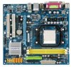
GA-M68SM-S2L Motherboard Layout KB_MS ATX_12V Socket AM2 DVI LPT VGA CPU_FAN ATX IDE USB LAN USB IT8716 AUDIO F_AUDIO PCIE_16 GA-M68SM-S2L FDD DDRII_1 DDRII_2 RTL 8211BL PCIE_1 PCI1 CI BIOS BATTERY CD_IN PCI2 CODEC COM SPDIF_O SYS_FAN SATAII3 SATAII1 nVIDIA® SATAII2 GeForce - Gigabyte GA-M68SM-S2L | Manual - Page 8
AM2 CPU CPU CLK+/-(200 MHz) DDR2 800/667/533 MHz DIMM Hyper Transport Dual Channel Memory PCI Express x16 DVI-D PCI Express Bus x1 PCIe CLK (100 MHz) 1 PCI Express x1 PCI Bus D-Sub RTL 8211BL LAN RJ45 nVIDIA® GeForce 7025/ nForce 630a 4 SATA 3Gb/s ATA-133/100/66/33 IDE Channel BIOS - Gigabyte GA-M68SM-S2L | Manual - Page 9
user's manual and follow these procedures: • Prior to installation, do not remove or break motherboard wrist strap when handling electronic components such as a motherboard, CPU or memory. If you do not have an the user. • If you are uncertain about any installation steps or have a problem related - Gigabyte GA-M68SM-S2L | Manual - Page 10
4 x SATA 3Gb/s connectors 1 x CPU fan header 1 x system fan header 1 x front panel header 1 x front panel audio header 1 x CD In connector 1 x S/PDIF Out header 3 x USB 2.0/1.1 headers 1 x serial port header 1 x chassis intrusion header 1 x power LED header GA-M68SM-S2L Motherboard - 10 - - Gigabyte GA-M68SM-S2L | Manual - Page 11
CPU/System overheating warning Š CPU/System fan fail warning Š CPU fan speed control (Note 2) Š 1 x 4 Mbit flash Š Use of licensed AWARD BIOS Š PnP 1.0a, DMI 2.0, SM BIOS 2.4, ACPI 1.0b Š Support for @BIOS Š Support for Download Center Š Support for Q-Flash Š Support for EasyTune (Note 3) Š Support - Gigabyte GA-M68SM-S2L | Manual - Page 12
card, memory, hard drive, etc. 1-3-1 Installing the CPU A. Locate the pin one (denoted by a small triangle) of the CPU socket and the CPU. A Small Triangle Mark Denotes Pin One of the Socket AM2 CPU Socket A Small Triangle Marking Denotes CPU Pin One AM2 CPU GA-M68SM-S2L Motherboard - 12 - - Gigabyte GA-M68SM-S2L | Manual - Page 13
below to correctly install the CPU into the motherboard CPU socket. Before installing the CPU, make sure to turn off the computer and unplug the power cord from the power outlet to prevent damage to the CPU. CPU Socket Locking Lever Step 1: Completely lift up the CPU socket locking lever. Step - Gigabyte GA-M68SM-S2L | Manual - Page 14
of the CPU cooler to the CPU fan header (CPU_FAN) on the motherboard. Use extreme care when removing the CPU cooler because the thermal grease/tape between the CPU cooler and CPU may adhere to the CPU. Inadequately removing the CPU cooler may damage the CPU. GA-M68SM-S2L Motherboard - 14 - Gigabyte GA-M68SM-S2L | Manual - Page 15
motherboard supports the memory. It is recommended that memory of the same capacity, brand, speed, and chips be used. (Go to GIGABYTE's website for the latest memory support list DDRII_1 Channel 1: DDRII_2 DDRII_1 DDRII_2 Due to CPU limitation, read the following guidelines before installing the - Gigabyte GA-M68SM-S2L | Manual - Page 16
the memory module. DDR2 DIMMs are not compatible to DDR DIMMs. Be sure to install DDR2 DIMMs on this motherboard. Notch DDR2 DIMM A DDR2 memory module has a notch, so it can only fit in one direction. will snap into place when the memory module is securely inserted. GA-M68SM-S2L Motherboard - 16 - - Gigabyte GA-M68SM-S2L | Manual - Page 17
an expansion card: • Make sure the motherboard supports the expansion card. Carefully read the manual that came with your expansion card. • Always If necessary, go to BIOS Setup to make any required BIOS changes for your expansion card(s). 7. Install the driver provided with the expansion card - Gigabyte GA-M68SM-S2L | Manual - Page 18
connector. Connect a monitor that supports D-Sub connection to this port. • This motherboard provides two ports for video output, DVI and D-Sub, and supports dual view function. • Due to an nVIDIA GeForce 7025/nForce 630a chipset limitation, the GA-M68SM-S2L does not support dual view function via - Gigabyte GA-M68SM-S2L | Manual - Page 19
speakers in a 4/5.1-channel audio configuration. Mic In Jack (Pink) The default Mic in jack. Microphones must be connected to this jack. Refer to the instructions on setting up a 2/4/5.1-channel audio configuration in Chapter 5, "Configuring 2/4/5.1-Channel Audio." - 19 - Hardware Installation - Gigabyte GA-M68SM-S2L | Manual - Page 20
devices. • After installing the device and before turning on the computer, make sure the device cable has been securely attached to the connector on the motherboard. GA-M68SM-S2L Motherboard - 20 - - Gigabyte GA-M68SM-S2L | Manual - Page 21
supply can supply enough stable power to all the components on the motherboard. Before connecting the power connector, first make sure the power supply the correct orientation. The 12V power connector mainly supplies power to the CPU. If the 12V power connector is not connected, the computer will - Gigabyte GA-M68SM-S2L | Manual - Page 22
disk drives supported are: 360 KB, 720 KB, 1.2 MB, 1.44 MB, and 2.88 MB. Before connecting a floppy disk drive, be sure to locate pin 1 of the connector and the floppy disk drive cable. The pin 1 of the cable is typically designated by a stripe of different color. 34 33 GA-M68SM-S2L Motherboard - Gigabyte GA-M68SM-S2L | Manual - Page 23
a single SATA device. The nVIDIA® GeForce 7025/ nForce 630a controller supports RAID 0, RAID 1, RAID 0+1, RAID 5 and JBOD. Refer to Chapter 5, "Configuring SATA Hard Drive(s)," for instructions on configuring a RAID array. 1 7 Pin No. 1 2 3 4 5 6 7 Definition GND TXP TXN GND RXN RXP GND Please - Gigabyte GA-M68SM-S2L | Manual - Page 24
S1 Blinking S3/S4/S5 Off 9) BATTERY The battery provides power to keep the values (such as BIOS configurations, date, and time information) in the CMOS when the computer is turned off. Replace the must be handled in accordance with local environmental regulations. GA-M68SM-S2L Motherboard - 24 - - Gigabyte GA-M68SM-S2L | Manual - Page 25
a beep code. One single short beep will be heard if no problem is detected at system startup. If a problem is detected, the BIOS may issue beeps in different patterns to indicate the problem. Refer to Chapter 5, "Troubleshooting," for information about beep codes. • HD (IDE Hard Drive Activity LED - Gigabyte GA-M68SM-S2L | Manual - Page 26
panel audio module that has different wire assignments, please contact the chassis manufacturer. 12) CD_IN (CD In Connector, Black) You may connect the audio cable that came with your optical drive to the header. Pin No. Definition 1 CD-L 1 2 GND 3 GND 4 CD-R GA-M68SM-S2L Motherboard - Gigabyte GA-M68SM-S2L | Manual - Page 27
digital S/PDIF out. Via an optional S/PDIF out cable, this header can connect to an audio device that supports digital audio in. For purchasing the optional S/PDIF out cable, please contact the local dealer. Pin No. Definition 1 Power 1 2 SPDIFO 3 GND Pin 1 (the red wire) of the S/ - Gigabyte GA-M68SM-S2L | Manual - Page 28
No Pin 16) CI (Chassis Intrusion Header) This motherboard provides a chassis detection feature that detects if the chassis cover has been removed. This function requires a chassis with chassis intrusion detection design. Pin No. Definition 1 1 Signal 2 GND GA-M68SM-S2L Motherboard - 28 - - Gigabyte GA-M68SM-S2L | Manual - Page 29
the jumper. Failure to do so may cause damage to the motherboard. • After system restart, go to BIOS Setup to load factory defaults (select Load Optimized Defaults) or manually configure the BIOS settings (refer to Chapter 2, "BIOS Setup," for BIOS configurations). - 29 - Hardware Installation - Gigabyte GA-M68SM-S2L | Manual - Page 30
GA-M68SM-S2L Motherboard - 30 - - Gigabyte GA-M68SM-S2L | Manual - Page 31
the GIGABYTE Q-Flash or @BIOS utility. • Q-Flash allows the user to quickly and easily upgrade or back up BIOS without entering the operating system. • @BIOS is a Windows-based utility that searches and downloads the latest version of BIOS from the Internet and updates the BIOS. For instructions on - Gigabyte GA-M68SM-S2L | Manual - Page 32
, the device boot order will still be based on BIOS Setup settings. You can access Boot Menu again to change the first boot device setting as needed. : Q-Flash Press the key to access the Q-Flash utility directly without having to enter BIOS Setup first. GA-M68SM-S2L Motherboard - 32 - - Gigabyte GA-M68SM-S2L | Manual - Page 33
F8: Q-Flash Load Fail-Safe Defaults Load Optimized Defaults Set Supervisor Password Set User Password Save & Exit Setup Exit Without Saving KLJI: Select Item F10: Save & Exit Setup Time, Date, Hard Disk Type... BIOS Setup Program Function Keys Move the selection bar to select an item - Gigabyte GA-M68SM-S2L | Manual - Page 34
CMOS and exit BIOS Setup. (Pressing can also carry out this task.) „ Exit Without Saving Abandon all changes and the previous settings remain in effect. Pressing to the confirmation message will exit BIOS Setup. (Pressing can also carry out this task.) GA-M68SM-S2L Motherboard - 34 - Gigabyte GA-M68SM-S2L | Manual - Page 35
] [None] [None] Drive A Floppy 3 Mode Support [1.44M, 3.5"] [Disabled] Halt On [All Errors] the three methods below: • Auto Lets BIOS automatically detect IDE/SATA devices during the POST Manual skip the detection of the device during the POST for faster system startup. Allows you to manually - Gigabyte GA-M68SM-S2L | Manual - Page 36
parameters manually, 44M/3.5", 2.88M/3.5". Floppy 3 Mode Support Allows you to specify whether the BIOS POST. Base Memory Also called conventional memory. Typically, 640 KB will be reserved for the MS-DOS operating system. Extended Memory The amount of extended memory. GA-M68SM-S2L Motherboard - Gigabyte GA-M68SM-S2L | Manual - Page 37
With virtualization, one computer system can function as multiple virtual systems. (Default: Disabled) AMD K8 Cool&Quiet control Auto Lets the AMD Cool'n'Quiet driver dynamically adjust the CPU clock and VIA to reduce heat output from your computer and its power consumption. (Default) Disabled - Gigabyte GA-M68SM-S2L | Manual - Page 38
Buffer Control option is set to Manual. Frame buffer size is the total amount of system memory allocated solely for the onboard graphics controller. MS-DOS, for example, will use only this memory for display. Options are: 16M, 32M, 64M(default), 128M, 256M, Disabled. GA-M68SM-S2L Motherboard - 38 - Gigabyte GA-M68SM-S2L | Manual - Page 39
On-Chip MAC Lan NV Serial-ATA 1 IDE Prefetch Mode Onchip SATA Mode Onboard Audio Function ` SMART LAN OnBoard LAN Boot ROM Onboard Copyright (C) 1984-2007 Award Software USB Device Setting USB Controllers USB Keyboard Function USB Mouse Function USB Storage Function Defaults - 39 - BIOS Setup - Gigabyte GA-M68SM-S2L | Manual - Page 40
Chip MAC Lan Enables or disables the onboard LAN function. controller. Onboard Audio Function Enables or disables the onboard audio function. (Default: Auto) If you wish to install a 3rd party add-in audio card instead of using the onboard audio, set this item to Disabled. GA-M68SM-S2L Motherboard - Gigabyte GA-M68SM-S2L | Manual - Page 41
LAN cable is attached to the motherboard, the Status fields of all four pairs of wires will show Open and the Length fields show 0.0m, as shown in the figure above. When LAN Cable Is Functioning Normally... If no cable problem is detected on the LAN of the attached LAN cable. - 41 - BIOS Setup - Gigabyte GA-M68SM-S2L | Manual - Page 42
to activate the boot ROM integrated with the onboard LAN chip. (Default: Disabled) Onboard Serial Port Enables mode. Options are: 3 (default), 1. USB Controllers Enables or disables the integrated USB controller. (Default: Enabled) Disabled will turn off all Enabled) GA-M68SM-S2L Motherboard - 42 - - Gigabyte GA-M68SM-S2L | Manual - Page 43
Suspend Power-On by Alarm x Day of Month Alarm x Time (hh:mm:ss) Alarm HPET Support (Note) HPET Mode (Note) Power On By Mouse Power On By Keyboard x KB Power ON up signal from a modem that supports wake-up function. (Default: Enabled) (Note) Supported on Windows® Vista® operating system only. - 43 - Gigabyte GA-M68SM-S2L | Manual - Page 44
system or removal of the AC power, or the settings may not be effective. HPET Support (Note) Enables or disables High Precision Event Timer (HPET) for Windows® Vista® operating the return of the AC power. (Note) Supported on Windows® Vista® operating system only. GA-M68SM-S2L Motherboard - 44 - - Gigabyte GA-M68SM-S2L | Manual - Page 45
IRQ Assignment Auto 3,4,5,7,9,10,11,12,14,15 +/-/PU/PD: Value F10: Save F6: Fail-Safe Defaults ESC: Exit F1: General Help F7: Optimized Defaults BIOS auto-assigns IRQ to the first PCI slot. (Default) Assigns IRQ 3,4,5,7,9,10,11,12,14,15 to the first PCI slot - Gigabyte GA-M68SM-S2L | Manual - Page 46
: Disabled (default), 60oC/140oF, 70oC/158oF, 80oC/176oF, 90oC/194oF. CPU/SYSTEM FAN Fail Warning Allows the system to emit warning sound if the CPU/system fan is not connected or fails. Check the fan condition or fan connection when this occurs. (Default: Disabled) GA-M68SM-S2L Motherboard - 46 - - Gigabyte GA-M68SM-S2L | Manual - Page 47
at full speed. (Default: Enabled) CPU Smart FAN Mode Specifies how to control CPU fan speed. This item is configurable only if CPU Smart FAN Control is set to Enabled. Auto Lets BIOS autodetect the type of CPU fan installed and sets the optimal CPU fan control mode. (Default) Voltage Sets - Gigabyte GA-M68SM-S2L | Manual - Page 48
Press on this item and then press the key to load the optimal BIOS default settings. The BIOS defaults settings helps the system to operate in optimum state. Always load the Optimized defaults after updating the BIOS or after clearing the CMOS values. GA-M68SM-S2L Motherboard - 48 - - Gigabyte GA-M68SM-S2L | Manual - Page 49
Setup, you must enter the supervisor password if you wish to make changes to BIOS settings. The user password only allows you to view the BIOS settings but not to make changes. To clear the password, press on the password item and when requested for the password, press again. - Gigabyte GA-M68SM-S2L | Manual - Page 50
Without Saving KLJI: Select Item F10: Save & Exit Setup Abandon all Data Press on this item and press the key. This exits the BIOS Setup without saving the changes made in BIOS Setup to the CMOS. Press or to return to the BIOS Setup Main Menu. GA-M68SM-S2L Motherboard - 50 - - Gigabyte GA-M68SM-S2L | Manual - Page 51
other drivers. • After the drivers are installed, follow the onscreen instructions to restart your system. You can install other applications included in the motherboard driver disk. • For USB 2.0 driver support under the Windows XP operating system, please install the Windows XP Service Pack - Gigabyte GA-M68SM-S2L | Manual - Page 52
all the tools and applications that GIGABYTE develops and some free software. You may press the Install button following an item to install it. 3-3 Driver CD Information This page provides information about the drivers, applications and tools in this driver disk. GA-M68SM-S2L Motherboard - 52 - - Gigabyte GA-M68SM-S2L | Manual - Page 53
3-4 Hardware Information This page provides information about the hardware devices on this motherboard. 3-5 Contact Us Check the contacts information of the GIGABYTE headquarter in Taiwan and the overseas branch offices on the last page of this manual. - 53 - Drivers Installation - Gigabyte GA-M68SM-S2L | Manual - Page 54
GA-M68SM-S2L Motherboard - 54 - - Gigabyte GA-M68SM-S2L | Manual - Page 55
compress and back up your system data and perform restoration of it. Supporting NTFS, FAT32, and FAT16 file systems, Xpress Recovery2 can back up is recommended to back up your system soon after the operating system and drivers are installed. • The amount of data and hard drive access speed may affect - Gigabyte GA-M68SM-S2L | Manual - Page 56
Drive 1. Set CD-ROM drive as the first boot device under "Advanced BIOS Features" in the BIOS Setup program. Save the changes and exit. 2. When partitioning your hard drive for example, NTFS) and begin the installation of the operating system (Figure 3). Figure 3 GA-M68SM-S2L Motherboard - 56 - - Gigabyte GA-M68SM-S2L | Manual - Page 57
Figure 4 Figure 5 5. If your hard drive is not properly partitioned before you install the operating system, you may create new partitions using free space on your hard drive (Figure 6, 7). However, if Disk Management shows the hard drive only contains the System partition without any unallocated - Gigabyte GA-M68SM-S2L | Manual - Page 58
from the motherboard driver disk to Award Modular BIOS v6.00PG, An Energy Star Ally Copyright (C) 1984-2007, Award Software, Inc. M68SM-S2L D1 . . . . : BIOS Setup/Q-Flash to check disk allocation. Figure 12 GA-M68SM-S2L Motherboard Xpress Recovery2 will automatically create a new partition to - Gigabyte GA-M68SM-S2L | Manual - Page 59
D. Using the Restore Function in Xpress Recovery2 Select RESTORE to restore the backup to your hard drive in case the system breaks down. The RESTORE option will not be present if no backup is created before (Figure 13, 14). Figure 13 Figure 14 E. Removing the Backup 1. If you wish to remove the - Gigabyte GA-M68SM-S2L | Manual - Page 60
Inc. M68SM-S2L D1 . . . . : BIOS Setup/Q-Flash : XpressRecovery2 : Boot Menu : Qflash 09/11/2007-NF-MCP68-6A61MG02C-00 Because BIOS flashing is potentially risky, please do it with caution. Inadequate BIOS flashing may result in system malfunction. GA-M68SM-S2L Motherboard - 60 - Gigabyte GA-M68SM-S2L | Manual - Page 61
KL:Move ESC:Reset :Power Off Total size : 0 Free size : 0 3. Select the BIOS update file and press . Make sure the BIOS update file matches your motherboard model. Step 2: The process of the system reading the BIOS file from the floppy disk is displayed on the screen - Gigabyte GA-M68SM-S2L | Manual - Page 62
Without Saving KLJI: Select Item F10: Save & Exit Setup Load Optimized Defaults Press to load BIOS defaults Step 6: Select Save & Exit Setup and then press to save settings to CMOS and exit BIOS Setup. The procedure is complete after the system restarts. GA-M68SM-S2L Motherboard - 62 - - Gigabyte GA-M68SM-S2L | Manual - Page 63
and Using @BIOS: Use the motherboard driver disk included with the motherboard to install @BIOS. • Installing the @BIOS utility. • Accessing the @BIOS utility. Select @BIOS and click Install. Click Start>All Programs>GIGABYTE>@BIOS C. Options and Instructions: 1. Save the Current BIOS File In - Gigabyte GA-M68SM-S2L | Manual - Page 64
in an unbootable system. • If the BIOS update file for your motherboard is not present on the @BIOS server site, please manually download the BIOS update file from GIGABYTE's website and follow the instructions in "Update the BIOS without Using the Internet Update Function" below. Step 4: As the - Gigabyte GA-M68SM-S2L | Manual - Page 65
the BIOS Setup program. EasyTune 5 provides the following functions (Note 1): overclocking/overvoltage, C.I.A./ M.I.B. (Note 2), smart fan control, and hardware monitoring and warning. (For instructions on using EasyTune5, read or download the information on/from the Support\Motherboard\Utility - Gigabyte GA-M68SM-S2L | Manual - Page 66
of space. • The recommended amount of memory to use for ReadyBoost acceleration is one to three times the amount of RAM installed in your computer. GA-M68SM-S2L Motherboard - 66 - - Gigabyte GA-M68SM-S2L | Manual - Page 67
controller mode in BIOS Setup. C . Configure a RAID array in RAID BIOS. (Note 1) D. Make a floppy disk containing the SATA RAID/AHCI driver. (Note 2) E. Install the SATA RAID/AHCI driver 2000 setup disk. • Motherboard driver disk. 5-1-1 Configuring the Onboard SATA Controller A. Installing SATA hard - Gigabyte GA-M68SM-S2L | Manual - Page 68
: Exit F1: General Help F7: Optimized Defaults The BIOS Setup menus described in this section may differ from the exact settings for your motherboard. The actual BIOS Setup menu options you will see shall depend on the motherboard you have and the BIOS version. GA-M68SM-S2L Motherboard - 68 - - Gigabyte GA-M68SM-S2L | Manual - Page 69
NVIDIA RAID setup utility. MediaShield ROM BIOS 10.0.0.5 Copyright (C) 2007 NVIDIA Corp a RAID mode. The supported RAID modes include Mirrored, Striped (Striped) is selected, you can manually set the stripe block size. In Array - Stripe Block: Optimal Free Disks Port Disk Model 1 ST3120026AS - Gigabyte GA-M68SM-S2L | Manual - Page 70
drives that are available for use as RAID array drives. Press to move to the Free Disks block. Select the target hard drives using the up or down arrow key and use the right [ESC] Quit [F6] Back [F7] Finish [TAB] Navigate [KL] Select [ENTER] Popup Figure 6 GA-M68SM-S2L Motherboard - 70 - - Gigabyte GA-M68SM-S2L | Manual - Page 71
to confirm or to cancel. Press to return to the Array List screen. To exit the NVIDIA RAID setup utility, press in the main menu or + in the Array List screen. Now, you can proceed to the installation of the SATA controller driver and operating system. - 71 - Appendix - Gigabyte GA-M68SM-S2L | Manual - Page 72
Note) For users without a startup disk: Use an alternative system and insert the motherboard driver disk. From your optical drive folder, double click the MENU.exe file in the BootDrv folder (Figure 3). A command prompt window will open similar to that in Figure 2. GA-M68SM-S2L Motherboard Figure - Gigabyte GA-M68SM-S2L | Manual - Page 73
prepared the SATA RAID/AHCI driver diskette and configured the required BIOS settings, you are ready to manually specify an adapter. Currently, Setup will load support for the following mass storage devices(s) * To specify additional SCSI adapters, CD-ROM drives, or special disk controllers - Gigabyte GA-M68SM-S2L | Manual - Page 74
one or some file(s) cannot be found, please check the floppy disk or copy the correct SATA RAID driver again from the motherboard driver disk. (Note) The selectable item(s) displayed in Figure 3 may differ according to the RAID or AHCI driver you will install. GA-M68SM-S2L Motherboard - 74 - - Gigabyte GA-M68SM-S2L | Manual - Page 75
one minute. Windows Setup Setup will load support for the following mass storage device(s): NVIDIA RAID Driver (required) NVIDIA nForce Storage Controller (required) * To specify additional SCSI adapters, CD-ROM drives, or special disk controllers for use with Windows, including those for which - Gigabyte GA-M68SM-S2L | Manual - Page 76
steps. When a screen similar to that below appears (RAID or AHCI hard drive(s) will not be detected at this stage), select Load Drivers. (Figure 7). Figure 7 Step 2: Specify the location where the driver is saved, such as your floppy disk (Figure 8). Figure 8 GA-M68SM-S2L Motherboard - 76 - - Gigabyte GA-M68SM-S2L | Manual - Page 77
, for example, when a screen (Note) as shown in Figure 9 appears, select NVIDIA nForce RAID Controller and press Next. Figure 9 Step 4: After the driver is loaded, the screen will show the RAID or AHCI hard drive(s). Select the location where you want to install the operating system and then - Gigabyte GA-M68SM-S2L | Manual - Page 78
-click the icon to access the Audio Control Panel. Before installing the audio driver, make sure the "Microsoft UAA Bus driver for High Definition Audio" has been installed from the motherboard driver disk and your operating system has been updated with the latest Service Pack for Windows. (Note - Gigabyte GA-M68SM-S2L | Manual - Page 79
Step 2: Click the Audio I/O tab. In the speaker list on the left, select 2CH Speaker, 4CH Speaker, or 6CH Channel Speakers: Front Speaker Out Rear Speaker Out Step 4: Everytime you connect an audio device to an audio jack, the Connected device box appears. Select the device according to the type of - Gigabyte GA-M68SM-S2L | Manual - Page 80
OK to activiate the AC'97 functionality. D. Muting the Back Panel Audio (For HD Audio Only): Click the tool icon on the Audio I/O tab. On the Connector Settings box, select the Mute rear panel output when front headphone plugged in check box. Click OK to complete. GA-M68SM-S2L Motherboard - 80 - - Gigabyte GA-M68SM-S2L | Manual - Page 81
in and out cable first if you want to output S/PDIF digital audio signals to an external decoder. A. Installing the S/PDIF Out Cable: Step 1: First, attach the connector at the end of the cable to the SPDIF_O header on your motherboard. Pin 1 (the red wire) of the S/PDIF out cable must align - Gigabyte GA-M68SM-S2L | Manual - Page 82
digital audio signals. S/PDIF Optical Cable B. Configuring S/PDIF out: Click the tool icon in the DIGITAL section. In the S/PDIF Settings dialog box, select an output sampling rate and select (or disable) the output source. Click OK to complete the configuration. GA-M68SM-S2L Motherboard - 82 - Gigabyte GA-M68SM-S2L | Manual - Page 83
5-2-3 Configuring Microphone Recording Step 1: After installing the audio driver, the Audio Manager icon will appear in your system tray. Double-click the icon to access the Audio Control Panel. Step 2: Connect your microphone to the Mic in jack (pink) on the back panel or the Line in jack on the - Gigabyte GA-M68SM-S2L | Manual - Page 84
device list, select Realtek HD Audio Input. Then set the recording sound level properly. Do NOT mute the recording sound, or you will not hear any sound when playing back the recording you just made. Select Realtek HD Audio Input in the Mixer device list GA-M68SM-S2L Motherboard Recording Control - Gigabyte GA-M68SM-S2L | Manual - Page 85
Controls. Click the Advanced button under a volume control option (e.g. Front Green In, Front Pink In). In the Other Controls field Using the Sound Recorder Recording the Sound: 1. Make sure you have connected the audio input device (e.g. microphone) to the computer. 2. On the File menu, choose - Gigabyte GA-M68SM-S2L | Manual - Page 86
setting error 1 long, 1 short: Memory or motherboard error 1 long, 2 short: Monitor or graphics card error 1 long, 3 short: Keyboard error 1 long, 9 short: BIOS ROM error Continuous long beeps: Graphics card not inserted properly Continuous short beeps: Power error GA-M68SM-S2L Motherboard - 86 - - Gigabyte GA-M68SM-S2L | Manual - Page 87
Procedure If you encounter any troubles during system startup, follow the troubleshooting procedure below to solve the problem. START Turn off the power. Remove all peripherals, connecting cables, and power cord etc. Make sure the motherboard does not short-circuit with the chassis or - Gigabyte GA-M68SM-S2L | Manual - Page 88
and solved. END If the procedure above is unable to solve your problem, contact the place of purchase or local dealer for help. Or go to the Support\Technical Service Zone page to submit your question. Our customer service staff will reply you as soon as possible. GA-M68SM-S2L Motherboard - 88 - - Gigabyte GA-M68SM-S2L | Manual - Page 89
GIGABYTE. Our Commitment to Preserving the Environment In addition to high-efficiency performance, all GIGABYTE motherboards office, your household waste disposal service or where you purchased the Customer Care number listed in your product's user's manual and we will be glad to help you - Gigabyte GA-M68SM-S2L | Manual - Page 90
disposed of properly. China Restriction of Hazardous Substances Table The following table is supplied in compliance with China's Restriction of Hazardous Substances (China RoHS) requirements: GA-M68SM-S2L Motherboard - 90 - - Gigabyte GA-M68SM-S2L | Manual - Page 91
- 91 - Appendix - Gigabyte GA-M68SM-S2L | Manual - Page 92
GA-M68SM-S2L Motherboard - 92 - - Gigabyte GA-M68SM-S2L | Manual - Page 93
- 93 - Appendix - Gigabyte GA-M68SM-S2L | Manual - Page 94
GA-M68SM-S2L Motherboard - 94 - - Gigabyte GA-M68SM-S2L | Manual - Page 95
231, Taiwan TEL: +886-2-8912-4888 FAX: +886-2-8912-4003 Tech. and Non-Tech. Support (Sales/Marketing) : http://ggts.gigabyte.com.tw WEB address (English): http://www.gigabyte.com.tw WEB address (Chinese): http://www.gigabyte.tw y G.B.T. INC. - U.S.A. TEL: +1-626-854-9338 FAX: +1-626-854-9339 Tech - Gigabyte GA-M68SM-S2L | Manual - Page 96
language in the language list on the top right corner of the website. y GIGABYTE Global Service System To submit a technical or non-technical (Sales/ Marketing) question, please link to : http://ggts.gigabyte.com.tw Then select your language to enter the system. GA-M68SM-S2L Motherboard - 96 -
-
 1
1 -
 2
2 -
 3
3 -
 4
4 -
 5
5 -
 6
6 -
 7
7 -
8
-
9
-
10
-
11
-
12
-
13
-
14
-
15
-
16
-
17
-
18
-
19
-
20
-
21
-
22
-
23
-
24
-
25
-
26
-
27
-
28
-
29
-
30
-
31
-
32
-
33
-
34
-
35
-
36
-
37
-
38
-
39
-
40
-
41
-
42
-
43
-
44
-
45
-
46
-
47
-
48
-
49
-
50
-
51
-
52
-
53
-
54
-
55
-
56
-
57
-
58
-
59
-
60
-
61
-
62
-
63
-
64
-
65
-
66
-
67
-
68
-
69
-
70
-
71
-
72
-
73
-
74
-
75
-
76
-
77
-
78
-
79
-
80
-
81
-
82
-
83
-
84
-
85
-
86
-
87
-
88
-
89
-
90
-
91
-
92
-
93
-
94
-
95
-
96
 |
 |

GA-M68SM-S2L
AM2 socket motherboard for
AMD Athlon
TM
64 FX processor/
AMD Athlon
TM
64 X2 Dual-Core processor/
AMD Athlon
TM
64 processor/AMD Sempron
TM
processor
User's Manual
Rev. 1003
12ME-M68SMS2L-1003R