Gigabyte GA-M720-ES3 Manual
Gigabyte GA-M720-ES3 Manual
 |
View all Gigabyte GA-M720-ES3 manuals
Add to My Manuals
Save this manual to your list of manuals |
Gigabyte GA-M720-ES3 manual content summary:
- Gigabyte GA-M720-ES3 | Manual - Page 1
GA-M720-ES3 AM2+/AM2 socket motherboard for AMD PhenomTM II processor/AMD PhenomTM processor/ AMD AthlonTM II processor/AMD AthlonTM processor/ AMD SempronTM processor User's Manual Rev. 1001 12ME-M720ES3-1001R - Gigabyte GA-M720-ES3 | Manual - Page 2
Motherboard GA-M720-ES3 June 25, 2009 Motherboard GA-M720-ES3 June 25, 2009 - Gigabyte GA-M720-ES3 | Manual - Page 3
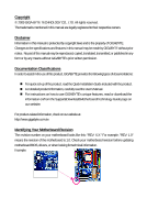
the product. For detailed product information, carefully read the User's Manual. For instructions on how to use GIGABYTE's unique features, read or download the information on/from the Support&Downloads\Motherboard\Technology Guide page on our website. For product-related information, check on - Gigabyte GA-M720-ES3 | Manual - Page 4
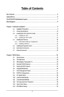
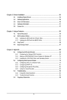
Table of Contents Box Contents ...6 OptionalItems...6 GA-M720-ES3 Motherboard Layout 7 Block Diagram...8 Chapter 1 Hardware Installation 9 1-1 Installation Card 17 1-6 Back Panel Connectors 18 1-7 Internal Connectors 20 Chapter 2 BIOS Setup 31 2-1 Startup Screen 32 2-2 The Main Menu 33 2-3 - Gigabyte GA-M720-ES3 | Manual - Page 5
Drivers 55 3-2 Software Applications 56 3-3 Driver CD Information 56 3-4 Hardware Information 57 3-5 Contact Us ...57 Chapter 4 Unique Features 59 4-1 Xpress Recovery2 59 4-2 BIOS Update Utilities 62 4-2-1 Updating the BIOS with the Q-Flash Utility 62 4-2-2 Updating the BIOS with the @BIOS - Gigabyte GA-M720-ES3 | Manual - Page 6
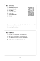
Box Contents GA-M720-ES3 motherboard Motherboard driver disk User's Manual Quick Installation Guide One IDE cable Two SATA 3Gb/s cables I/O Shield • The box contents above are for reference only and the actual items shall depend on product package - Gigabyte GA-M720-ES3 | Manual - Page 7
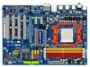
GA-M720-ES3 Motherboard Layout KB_MS RCA_SPDIF R_USB R_USB R_USB USB_LAN ATX_12V Socket AM2 PWR_FAN F_AUDIO AUDIO CPU_FAN PCIEX1_1 RTL8111C PCIEX1_2 PCIEX16 CODEC PCI1 PCI2 NVIDIA® nForce 720D GA-M720-ES3 SATA2_2 SATA2_1 SATA2_0 SATA2_5 SATA2_4 SATA2_3 BATTERY DDR2_1 DDR2_2 DDR2_3 - Gigabyte GA-M720-ES3 | Manual - Page 8
Express x16 PCI Express x16 AM3/AM2+/AM2 CPU CPU CLK+/-(200 MHz) DDR2 1200 (Note)/1066/800 MHz BIOS Floppy COM Port PS/2 KB/Mouse Surround Speaker Out Center/Subwoofer Speaker Out Side Speaker Out MIC Line Out Line In S/PDIF Out PCI CLK (33 MHz) (Note) Whether 1200 MHz memory speed is supported - Gigabyte GA-M720-ES3 | Manual - Page 9
, carefully read the user's manual and follow these procedures: • Prior to installation, do not remove or break motherboard S/N (Serial Number) sticker or you are uncertain about any installation steps or have a problem related to the use of the product, please consult a certified computer technician. - Gigabyte GA-M720-ES3 | Manual - Page 10
Connectors Support for AM3/AM2+/AM2 processors: AMD PhenomTM II processor/AMD PhenomTM processor/ AMD AthlonTM II processor/AMD AthlonTM processor/ AMD SempronTM processor (Go to GIGABYTE's website for the latest CPU support list.) 5200/2000 MT/s NVIDIA® nForce 720D chipset 4 x 1.8V DDR2 DIMM - Gigabyte GA-M720-ES3 | Manual - Page 11
fan speed control function is supported will depend on the CPU/ System cooler you install. (Note 4) Available functions in EasyTune may differ by motherboard model. (Note 5) Due to the hardware limitation, you must install the AMD AM3/ AM2+ Series CPU toenable support for Easy Energy Saver. - 11 - Gigabyte GA-M720-ES3 | Manual - Page 12
install the CPU: • Make sure that the motherboard supports the CPU. (Go to GIGABYTE's website for the latest CPU support list.) • Always turn off the computer Denotes Pin One of the Socket AM2 Socket A Small Triangle Marking Denotes CPU Pin One AM3/AM2+/AM2 CPU GA-M720-ES3 Motherboard - 12 - - Gigabyte GA-M720-ES3 | Manual - Page 13
B. Follow the steps below to correctly install the CPU into the motherboard CPU socket. Before installing the CPU, make sure to turn off the computer and unplug the power cord from the power outlet to prevent damage - Gigabyte GA-M720-ES3 | Manual - Page 14
of the CPU cooler to the CPU fan header (CPU_FAN) on the motherboard. Use extreme care when removing the CPU cooler because the thermal grease/tape between the CPU cooler and CPU may adhere to the CPU. Inadequately removing the CPU cooler may damage the CPU. GA-M720-ES3 Motherboard - 14 - - Gigabyte GA-M720-ES3 | Manual - Page 15
motherboard supports the memory. It is recommended that memory of the same capacity, brand, speed, and chips be used. (Go to GIGABYTE's website for the latest memory support motherboard provides four DDR2 memory sockets and supports Dual Channel Technology. After the memory is installed, the BIOS - Gigabyte GA-M720-ES3 | Manual - Page 16
outlet to prevent damage to the memory module. DDR2 DIMMs are not compatible to DDR DIMMs. Be sure to install DDR2 DIMMs on this motherboard. Notch DDR2 DIMM A DDR2 memory module has a notch, so it can snap into place when the memory module is securely inserted. GA-M720-ES3 Motherboard - 16 - - Gigabyte GA-M720-ES3 | Manual - Page 17
an expansion card: • Make sure the motherboard supports the expansion card. Carefully read the manual that came with your expansion card. • Always If necessary, go to BIOS Setup to make any required BIOS changes for your expansion card(s). 7. Install the driver provided with the expansion card - Gigabyte GA-M720-ES3 | Manual - Page 18
audio in connector. USB Port The USB port supports the USB 2.0/1.1 specification. Use this port for USB motherboard. • When removing the cable, pull it straight out from the connector. Do not rock it side to side to prevent an electrical short inside the cable connector. GA-M720-ES3 Motherboard - Gigabyte GA-M720-ES3 | Manual - Page 19
to perform different functions via the audio software. Only microphones still MUST be connected to the default Mic in jack ( ). Refer to the instructions on setting up a 2/4/5.1/ 7.1-channel audio configuration in Chapter 5, "Configuring 2/4/5.1/7.1-Channel Audio." - 19 - Hardware Installation - Gigabyte GA-M720-ES3 | Manual - Page 20
devices. • After installing the device and before turning on the computer, make sure the device cable has been securely attached to the connector on the motherboard. GA-M720-ES3 Motherboard - 20 - - Gigabyte GA-M720-ES3 | Manual - Page 21
2x12 Main Power Connector) With the use of the power connector, the power supply can supply enough stable power to all the components on the motherboard. Before connecting the power connector, first make sure the power supply is turned off and all devices are properly installed. The power connector - Gigabyte GA-M720-ES3 | Manual - Page 22
(Floppy Disk Drive Connector) This connector is used to connect a floppy disk drive. The types of floppy disk drives supported are: 360 KB, 720 KB, 1.2 MB, 1.44 MB, and 2.88 MB. Before connecting a floppy disk drive , please contact the local dealer. 33 1 34 2 GA-M720-ES3 Motherboard - 22 - - Gigabyte GA-M720-ES3 | Manual - Page 23
are compatible with SATA 1.5Gb/s standard. Each SATA connector supports a single SATA device. The NVIDIA® nForce 720D controller supports RAID 0, RAID 1, RAID 5, RAID 10, and JBOD. Refer to Chapter 5, "Configuring SATA Hard Drive(s)," for instructions on configuring a RAID array. Pin No. Definition - Gigabyte GA-M720-ES3 | Manual - Page 24
3 MPD- 1 System Status LED S0 On S1 Blinking S3/S4/S5 Off 10) BATTERY The battery provides power to keep the values (such as BIOS configurations, date, and time information) in the CMOS when be handled in accordance with local environmental regulations. GA-M720-ES3 Motherboard - 24 - - Gigabyte GA-M720-ES3 | Manual - Page 25
S1 sleep state. The LED is off when the system is in S3/S4/S5 Off S3/S4 sleep state or powered off (S5). • PW (Power Switch problem is detected at system startup. If a problem is detected, the BIOS may issue beeps in different patterns to indicate the problem. Refer to Chapter 5, "Troubleshooting - Gigabyte GA-M720-ES3 | Manual - Page 26
GND 10 NC • The front panel audio header supports HD audio by default. If your chassis provides an AC'97 front panel audio module, refer to the instructions on how to activate AC'97 functionality via header. Pin No. Definition 1 CD-L 1 2 GND 3 GND 4 CD-R GA-M720-ES3 Motherboard - 26 - - Gigabyte GA-M720-ES3 | Manual - Page 27
supports digital S/PDIF out and connects a S/PDIF digital audio cable (provided by expansion cards) for digital audio output from your motherboard information about connecting the S/PDIF digital audio cable, carefully read the manual for your expansion card. 1 Pin No. Definition 1 SPDIFO 2 - Gigabyte GA-M720-ES3 | Manual - Page 28
NRI No Pin 17) CI (Chassis Intrusion Header) This motherboard provides a chassis detection feature that detects if the chassis cover has been removed. This function requires a chassis with chassis intrusion detection design. Pin No. Definition 1 1 Signal 2 GND GA-M720-ES3 Motherboard - 28 - - Gigabyte GA-M720-ES3 | Manual - Page 29
the jumper. Failure to do so may cause damage to the motherboard. • After system restart, go to BIOS Setup to load factory defaults (select Load Optimized Defaults) or manually configure the BIOS settings (refer to Chapter 2, "BIOS Setup," for BIOS configurations). - 29 - Hardware Installation - Gigabyte GA-M720-ES3 | Manual - Page 30
GA-M720-ES3 Motherboard - 30 - - Gigabyte GA-M720-ES3 | Manual - Page 31
latest version of BIOS from the Internet and updates the BIOS. For instructions on using the Q-Flash and @BIOS utilities, refer to Chapter 4, "BIOS Update Utilities." • Because BIOS flashing is potentially risky, if you do not encounter problems using the current version of BIOS, it is recommended - Gigabyte GA-M720-ES3 | Manual - Page 32
, the device boot order will still be based on BIOS Setup settings. You can access Boot Menu again to change the first boot device setting as needed. : Q-FLASH Press the key to access the Q-Flash utility directly without having to enter BIOS Setup first. GA-M720-ES3 Motherboard - 32 - - Gigabyte GA-M720-ES3 | Manual - Page 33
& Exit Setup Exit Without Saving ESC: Quit F8: Q-Flash Select Item F10: Save & Exit Setup F11: Save CMOS to BIOS F12: Load CMOS from BIOS Change CPU's Clock & Voltage BIOS Setup Program Function Keys Move the selection bar to select an item Execute command or enter the submenu - Gigabyte GA-M720-ES3 | Manual - Page 34
CMOS and exit BIOS Setup. (Pressing can also carry out this task.) Exit Without Saving Abandon all changes and the previous settings remain in effect. Pressing to the confirmation message will exit BIOS Setup. (Pressing can also carry out this task.) GA-M720-ES3 Motherboard - 34 - Gigabyte GA-M720-ES3 | Manual - Page 35
Graphics Booster x VGA Core Clock DRAM Configuration ******** System Voltage Optimized System Voltage Control x DDR2 Voltage Control x Chipset/PCIE Voltage x HT-Link Voltage x CPU NB VID Control (Note ) This item is present only if you install a CPU that supports this feature. - 35 - BIOS Setup - Gigabyte GA-M720-ES3 | Manual - Page 36
with the CPU specifications. HT Link Frequency Allows you to manually set the frequency for the HT Link between the CPU and chipset. Auto BIOS will automatically adjust the HT Link Frequency. (Default) 200 Enabled. The core clock can be increased by 1% ~ 50%. GA-M720-ES3 Motherboard - 36 - - Gigabyte GA-M720-ES3 | Manual - Page 37
the memory clock. Auto lets BIOS automatically set the memory clock as required. Manual allows all clock control items below to be configurable. (Default: Auto) Memory Clock This option is configurable only when Set Memory Clock is set to Manual. When you use a AM3/AM2+ CPU: X2.00 Sets Memory - Gigabyte GA-M720-ES3 | Manual - Page 38
Options are: Auto (default), 2T, 3T. Row Cycle Time Options are: Auto (default), 11T~26T. RAS to RAS Delay Options are: Auto (default), 2T~5T. GA-M720-ES3 Motherboard - 38 - - Gigabyte GA-M720-ES3 | Manual - Page 39
to manually set the system voltages. Auto lets BIOS automatically set the system voltages as required. Manual allows all voltage control items below to be configurable. (Default: Auto) DDR2 CPU. (Note) This item is present only if you install a CPU that supports this feature. - 39 - BIOS Setup - Gigabyte GA-M720-ES3 | Manual - Page 40
] [None] [None] Drive A Floppy 3 Mode Support [1.44M, 3.5"] [Disabled] Halt On [All, But methods below: • Auto • None Lets BIOS automatically detect IDE/SATA devices during the faster system startup. • Manual Allows you to manually enter the specifications of GA-M720-ES3 Motherboard - 40 - - Gigabyte GA-M720-ES3 | Manual - Page 41
to enter the parameters manually, refer to the information 25", 720K/3.5", 1.44M/3.5", 2.88M/3.5". Floppy 3 Mode Support Allows you to specify whether the installed floppy disk drive will not stop for any error. All Errors Whenever the BIOS detects a non-fatal error the system boot will stop - Gigabyte GA-M720-ES3 | Manual - Page 42
1984-2009 Award Software Advanced BIOS Features AMD C1E Support Virtualization Patch AMD TLB Erratum AMD K8 Cool&Quiet control Auto Lets the AMD Cool'n'Quiet driver dynamically adjust the CPU clock and VIA to reduce heat install a CPU that supports this feature. GA-M720-ES3 Motherboard - 42 - - Gigabyte GA-M720-ES3 | Manual - Page 43
Show Allows you to determine whether to display the GIGABYTE Logo at system startup. Disabled displays normal POST message. (Default: Enabled) Backup BIOS Image to HDD Allows the system to copy the BIOS image file to the hard drive. If the system BIOS is corrupted, it will be recovered from this - Gigabyte GA-M720-ES3 | Manual - Page 44
ROM Onboard Serial Port OnChip USB USB Memory Type USB Keyboard Support USB Mouse Support Legacy USB storage detect [Enabled] [Enabled] [IDE] [Auto is an interface specification that allows the storage driver to enable advanced Serial ATA features such as Native . GA-M720-ES3 Motherboard - 44 - - Gigabyte GA-M720-ES3 | Manual - Page 45
LAN Cable Is Attached... If no LAN cable is attached to the motherboard, the Status fields of all four pairs of wires will show Open or when the LAN Boot ROM is activated. When a Cable Problem Occurs... If a cable problem occurs on a specified pair of wires, the Status field will 45 - BIOS Setup - Gigabyte GA-M720-ES3 | Manual - Page 46
-DOS. (Default: Disabled) USB Mouse Support Allows USB mouse to be used in MS-DOS. (Default: Disabled) Legacy USB storage detect Determines whether to detect USB storage devices, including USB flash drives and USB hard drives during the POST. (Default: Enabled) GA-M720-ES3 Motherboard - 46 - - Gigabyte GA-M720-ES3 | Manual - Page 47
Support (Note) HPET Mode (Note) ON Password AC Back Function [S3(STR)] [Instant-off] [ S3(STR) Enables the system to enter the ACPI S3 (Suspend to RAM) sleep state (default). In S3 supports wake-up function. (Default: Enabled) (Note) Supported on Windows® Vista® operating system only. - Gigabyte GA-M720-ES3 | Manual - Page 48
USB Resume from Suspend Allows the system to be awakened from ACPI S3 sleep state by a wake-up signal from the installed USB device. (Default: Enabled last known awake state upon the return of the AC power. (Note) Supported on Windows® Vista® operating system only. GA-M720-ES3 Motherboard - 48 - - Gigabyte GA-M720-ES3 | Manual - Page 49
IRQ Assignment Auto 3,4,5,7,9,10,11,12,14,15 +/-/PU/PD: Value F10: Save F6: Fail-Safe Defaults ESC: Exit F1: General Help F7: Optimized Defaults BIOS auto-assigns IRQ to the first PCI slot. (Default) Assigns IRQ 3,4,5,7,9,10,11,12,14,15 to the first PCI slot - Gigabyte GA-M720-ES3 | Manual - Page 50
Award Software PC Health Status Hardware Thermal Control Reset Case Open Status Case Opened Vcore DDR2 1.8V +3.3V +12V Current System Temperature Current CPU Temperature Current CPU FAN Speed Current Case Opened field will show "No" at next boot. (Default: Disabled) GA-M720-ES3 Motherboard - 50 - - Gigabyte GA-M720-ES3 | Manual - Page 51
detection device attached to the motherboard CI header. If the system then restart your system. Current Voltage(V) Vcore/DDR2 1.8V/+3.3V/+12V Displays the current system if CPU Smart FAN Control is set to Enabled. Auto Lets BIOS autodetect the type of CPU fan installed and sets the optimal - Gigabyte GA-M720-ES3 | Manual - Page 52
Press on this item and then press the key to load the optimal BIOS default settings. The BIOS defaults settings helps the system to operate in optimum state. Always load the Optimized defaults after updating the BIOS or after clearing the CMOS values. GA-M720-ES3 Motherboard - 52 - - Gigabyte GA-M720-ES3 | Manual - Page 53
changes. When the Password Check item is set to System, you must enter the supervisor password (or user password) at system startup and when entering BIOS Setup. User Password When the Password Check item is set to System, you must enter the supervisor password (or user password) at system startup - Gigabyte GA-M720-ES3 | Manual - Page 54
Setup F11: Save CMOS to BIOS F12: Load CMOS from BIOS Abandon all Data Press on this item and press the key. This exits the BIOS Setup without saving the changes made in BIOS Setup to the CMOS. Press or to return to the BIOS Setup Main Menu. GA-M720-ES3 Motherboard - 54 - - Gigabyte GA-M720-ES3 | Manual - Page 55
other drivers. • After the drivers are installed, follow the onscreen instructions to restart your system. You can install other applications included in the motherboard driver disk. • For USB 2.0 driver support under the Windows XP operating system, please install the Windows XP Service Pack - Gigabyte GA-M720-ES3 | Manual - Page 56
all the tools and applications that GIGABYTE develops and some free software. You may press the Install button following an item to install it. 3-3 Driver CD Information This page provides information about the drivers, applications and tools in this driver disk. GA-M720-ES3 Motherboard - 56 - - Gigabyte GA-M720-ES3 | Manual - Page 57
Information This page provides information about the hardware devices on this motherboard. 3-5 Contact Us For the detailed contact information of the GIGABYTE Taiwan headquarter or worldwide branch offices, click the URL on this page to link to the GIGABYTE Website. - 57 - Drivers Installation - Gigabyte GA-M720-ES3 | Manual - Page 58
GA-M720-ES3 Motherboard - 58 - - Gigabyte GA-M720-ES3 | Manual - Page 59
compress and back up your system data and perform restoration of it. Supporting NTFS, FAT32, and FAT16 file systems, Xpress Recovery2 can back up is recommended to back up your system soon after the operating system and drivers are installed. • The amount of data and hard drive access speed may affect - Gigabyte GA-M720-ES3 | Manual - Page 60
Xpress Recovery2 cannot save the backup file. B. Accessing Xpress Recovery2 1. Boot from the motherboard driver disk to access Xpress Recovery2 for the first time. When you see the following message: 2: When finished, go to Disk Management to check disk allocation. GA-M720-ES3 Motherboard - 60 - - Gigabyte GA-M720-ES3 | Manual - Page 61
D. Using the Restore Function in Xpress Recovery2 Select RESTORE to restore the backup to your hard drive in case the system breaks down. The RESTORE option will not be present if no backup is created before. E. Removing the Backup Step 1: If you wish to remove the backup file, select REMOVE. F. - Gigabyte GA-M720-ES3 | Manual - Page 62
Software, Inc. M720-ES3 E3c . . . . : BIOS Setup : XpressRecovery2 : Boot Menu : Qflash 06/10/2009-NF-MCP78-6A61OG09C-00 Because BIOS flashing is potentially risky, please do it with caution. Inadequate BIOS flashing may result in system malfunction. GA-M720-ES3 Motherboard - 62 - Gigabyte GA-M720-ES3 | Manual - Page 63
ESC:Reset :Power Off Total size : 0 Free size : 0 3. Select the BIOS update file and press . Make sure the BIOS update file matches your motherboard model. Step 2: The process of the system reading the BIOS file from the floppy disk is displayed on the screen. When the - Gigabyte GA-M720-ES3 | Manual - Page 64
Setup F11: Save CMOS to BIOS F12: Load CMOS from BIOS Load Optimized Defaults Press to load BIOS defaults Step 6: Select Save & Exit Setup and then press to save settings to CMOS and exit BIOS Setup. The procedure is complete after the system restarts. GA-M720-ES3 Motherboard - 64 - - Gigabyte GA-M720-ES3 | Manual - Page 65
. If the BIOS update file for your motherboard is not present on the @BIOS server site, please manually download the BIOS update file from GIGABYTE's website and follow the instructions in "Update the BIOS without Using the Internet Update Function" below. 2. Update the BIOS without Using the - Gigabyte GA-M720-ES3 | Manual - Page 66
4-3 EasyTune 6 GIGABYTE's EasyTune 6 is a simple EasyTune 6 may differ by motherboard model. Grayed-out area(s) indicates that the item is not configurable or the function is not supported. Incorrectly doing overclock/overvoltage other unexpected results may occur. GA-M720-ES3 Motherboard - 66 - - Gigabyte GA-M720-ES3 | Manual - Page 67
The Easy Energy Saver Interface A. Meter Mode In Meter Mode, GIGABYTE Easy Energy Saver shows how much power they have saved in a 15 Live Utility Update (Check for the latest utility version) • The above data is for reference only. Actual performance may vary depending on motherboard model. • CPU - Gigabyte GA-M720-ES3 | Manual - Page 68
continue to run in taskbar) 13 INFO/Help 14 Live Utility Update (Check for the latest utility version) C. Stealth Mode In the hardware limitation, you must install the AMD AM3/ AM2+ Series CPU toenable support for Easy Energy Saver. (Note 2) Maximize system GA-M720-ES3 Motherboard - 68 - - Gigabyte GA-M720-ES3 | Manual - Page 69
BIOS Setup. C . Configure a RAID array in RAID BIOS. (Note 1) D. Make a floppy disk containing the SATA RAID/AHCI driver for Windows XP. (Note 2) E. Install the SATA RAID/AHCI driver disk. • Windows Vista/XP setup disk. • Motherboard driver disk. 5-1-1 Configuring the Onboard SATA Controller A. - Gigabyte GA-M720-ES3 | Manual - Page 70
Keyboard Support USB Mouse Support Legacy USB BIOS Setup. The BIOS Setup menus described in this section may differ from the exact settings for your motherboard. The actual BIOS Setup menu options you will see shall depend on the motherboard you have and the BIOS version. GA-M720-ES3 Motherboard - Gigabyte GA-M720-ES3 | Manual - Page 71
arrow key to select a RAID mode. The supported RAID modes include Mirrored, Striped, Spanned, Striped 4: If RAID 0 (Striped) is selected, you can manually set the stripe block size. In the Stripe Block field 4 KB to 128 KB RAID Mode: Striped MediaShield BIOS Apr 25 2008 - Define a New Array - - Gigabyte GA-M720-ES3 | Manual - Page 72
key to add the hard drives to the Array Disks block (Figure 4). RAID Mode: Striped MediaShield BIOS Apr 25 2008 - Define a New Array - Stripe Block: Optimal Free Disks Port Disk Model ] Quit [F6] Back [F7] Finish [TAB] Navigate [] Select [ENTER] Popup Figure 5 GA-M720-ES3 Motherboard - 72 - - Gigabyte GA-M720-ES3 | Manual - Page 73
created (Figure 6). (Note: BBS stands for BIOS Boot Specification. This indicates that the boot device is defined in the BIOS.) Boot BBS MediaShield BIOS Apr 25 2008 - Array List - Status , you can proceed to the installation of the SATA controller driver and operating system. - 73 - Appendix - Gigabyte GA-M720-ES3 | Manual - Page 74
users without a startup disk: Use an alternative system and insert the motherboard driver disk. From your optical drive folder, double click the MENU.exe file in the BootDrv folder (Figure 3). A command prompt window will open similar to that in Figure 2. GA-M720-ES3 Motherboard Figure 3 - 74 - - Gigabyte GA-M720-ES3 | Manual - Page 75
and Operating System With the SATA RAID driver diskette and correct BIOS settings, you are ready to install Windows driver installation. When completed, proceed with the Windows XP installation. Windows Setup You have chosen to configure a SCSI Adapter for use with Windows, using a device support - Gigabyte GA-M720-ES3 | Manual - Page 76
\Vista32RAID For Windows Vista 64-bit, browse to the Vista64RAID folder (Figure 4). Method B: Insert the USB flash drive containing the driver files and browse to the Vista32RAID (for Windows Vista 32-bit) or Vista64RAID (for Windows Vista 64-bit) folder. GA-M720-ES3 Motherboard Figure 4 - 76 - - Gigabyte GA-M720-ES3 | Manual - Page 77
Step 3: When a screen as shown in Figure 5 appears, select NVIDIA nForce RAID Controller and press Next. Figure 5 Step 4: After the driver is loaded, the screen will show the RAID hard drive. Select the RAID hard drive onto which you want to install the operating system and - Gigabyte GA-M720-ES3 | Manual - Page 78
array and click Next. Step 5: Click Finish to start the rebuilding process. Step 6: The rebuilding progress is displayed in the View Storage Configuration sub-menu. GA-M720-ES3 Motherboard - 78 - - Gigabyte GA-M720-ES3 | Manual - Page 79
audio driver. manually configure the jack for microphone functionality. • Audio signals will be present on both of the front and back panel audio connections simultaneously. If you want to mute the back panel audio (only supported when using an HD front panel audio module), refer to instructions - Gigabyte GA-M720-ES3 | Manual - Page 80
open the Device advanced settings dialog box. Select the Mute the rear output device, when a front headphone plugged in check box. Click OK to complete. GA-M720-ES3 Motherboard - 80 - - Gigabyte GA-M720-ES3 | Manual - Page 81
5-2-2 Configuring S/PDIF Out S/PDIF Out: The S/PDIF Out jacks can transmit audio signals to an external decoder for decoding to get the best audio quality. 1. Connecting a S/PDIF Out Cable S/PDIF Coaxial Cable S/PDIF Optical Cable Connect a S/PDIF coaxial cable or a S/PDIF optical cable (either - Gigabyte GA-M720-ES3 | Manual - Page 82
5-2-3 Configuring Microphone Recording Step 1: After installing the audio driver, the HD Audio Manager icon will appear in the notification area. Doubleclick the icon to sound input default device to microphone, right-click on Microphone and select Set Default Device. GA-M720-ES3 Motherboard - 82 - - Gigabyte GA-M720-ES3 | Manual - Page 83
Step 4: To raise the recording and playback volume for the microphone, click the Microphone Boost icon on the right of the Recording Volume slider and set the Microphone Boost level. Step 5: After completing the settings above, click Start, point to Programs, point to Accessories, and then click - Gigabyte GA-M720-ES3 | Manual - Page 84
. Be sure to save the recorded audio file upon completion. B. Playing the Recorded Sound: You can play your recording in a digital media player program that supports your audio file format. GA-M720-ES3 Motherboard - 84 - - Gigabyte GA-M720-ES3 | Manual - Page 85
5-3 Troubleshooting 5-3-1 Frequently Asked Questions To read more FAQs for your motherboard, please go to the Support&Downloads\Motherboard\FAQ page on GIGABYTE's website. Q:In the BIOS Setup program, why are some BIOS options missing? A: Some advanced options are hidden in the BIOS Setup program. - Gigabyte GA-M720-ES3 | Manual - Page 86
troubles during system startup, follow the troubleshooting procedure below to solve the problem. START Turn off the power. Remove all peripherals, connecting cables, and power cord etc. Make sure the motherboard A The problem is verified and solved. (Continued...) GA-M720-ES3 Motherboard - 86 - - Gigabyte GA-M720-ES3 | Manual - Page 87
to save changes and exit BIOS Setup. No The keyboard or keyboard connec- tor might fail. The problem is verified and solved. problem, contact the place of purchase or local dealer for help. Or go to the Support&Downloads\Technical Service Zone page to submit your question. Our customer service - Gigabyte GA-M720-ES3 | Manual - Page 88
GIGABYTE. Our Commitment to Preserving the Environment In addition to high-efficiency performance, all GIGABYTE motherboards waste disposal service or where us at the Customer Care number listed in your product's user's manual and we will be glad to help you with your effort. GA-M720-ES3 Motherboard - Gigabyte GA-M720-ES3 | Manual - Page 89
Finally, we suggest that you practice other environmentally friendly actions by understanding and using the energy-saving features of this product (where applicable), recycling the inner and outer packaging (including shipping containers) this product was delivered in, and by disposing of or - Gigabyte GA-M720-ES3 | Manual - Page 90
GA-M720-ES3 Motherboard - 90 - - Gigabyte GA-M720-ES3 | Manual - Page 91
- 91 - Appendix - Gigabyte GA-M720-ES3 | Manual - Page 92
GA-M720-ES3 Motherboard - 92 - - Gigabyte GA-M720-ES3 | Manual - Page 93
- 93 - Appendix - Gigabyte GA-M720-ES3 | Manual - Page 94
GA-M720-ES3 Motherboard - 94 - - Gigabyte GA-M720-ES3 | Manual - Page 95
.com.tw WEB address (English): http://www.gigabyte.com.tw WEB address (Chinese): http://www.gigabyte.tw G.B.T. INC. - U.S.A. TEL: +1-626-854-9338 FAX: +1-626-854-9339 Tech. Support: http://rma.gigabyte-usa.com Web address: http://www.gigabyte.us G.B.T. INC (USA) - Mexico Tel: +1-626-854-9338 - Gigabyte GA-M720-ES3 | Manual - Page 96
language in the language list on the top right corner of the website. GIGABYTE Global Service System To submit a technical or non-technical (Sales/ Marketing) question, please link to : http://ggts.gigabyte.com.tw Then select your language to enter the system. GA-M720-ES3 Motherboard - 96 -
-
 1
1 -
 2
2 -
 3
3 -
 4
4 -
 5
5 -
 6
6 -
 7
7 -
8
-
9
-
10
-
11
-
12
-
13
-
14
-
15
-
16
-
17
-
18
-
19
-
20
-
21
-
22
-
23
-
24
-
25
-
26
-
27
-
28
-
29
-
30
-
31
-
32
-
33
-
34
-
35
-
36
-
37
-
38
-
39
-
40
-
41
-
42
-
43
-
44
-
45
-
46
-
47
-
48
-
49
-
50
-
51
-
52
-
53
-
54
-
55
-
56
-
57
-
58
-
59
-
60
-
61
-
62
-
63
-
64
-
65
-
66
-
67
-
68
-
69
-
70
-
71
-
72
-
73
-
74
-
75
-
76
-
77
-
78
-
79
-
80
-
81
-
82
-
83
-
84
-
85
-
86
-
87
-
88
-
89
-
90
-
91
-
92
-
93
-
94
-
95
-
96
 |
 |

GA-M720-ES3
AM2+/AM2 socket motherboard for
AMD Phenom
TM
II processor/AMD Phenom
TM
processor/
AMD Athlon
TM
II processor/AMD Athlon
TM
processor/
AMD Sempron
TM
processor
User's Manual
Rev. 1001
12ME-M720ES3-1001R