Gigabyte GA-MA770T-UD3 Manual - Page 26
F_PANEL Front Panel Header - motherboard led wire
 |
View all Gigabyte GA-MA770T-UD3 manuals
Add to My Manuals
Save this manual to your list of manuals |
Page 26 highlights
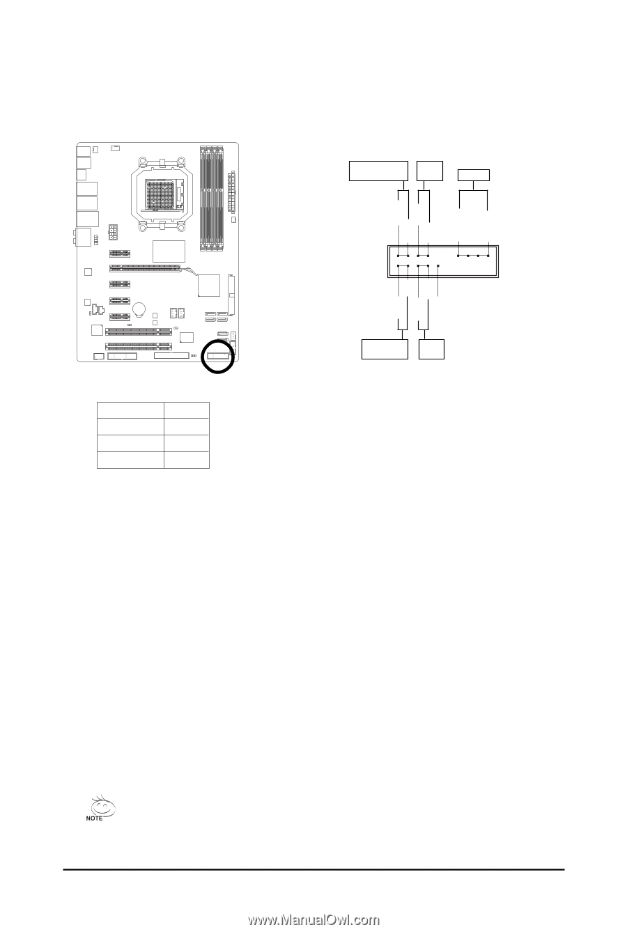
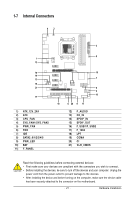
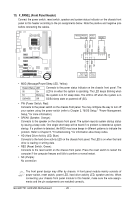
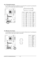
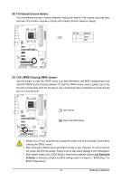
11) F_PANEL (Front Panel Header) Connect the power switch, reset switch, speaker and system status indicator on the chassis front panel to this header according to the pin assignments below. Note the positive and negative pins before connecting the cables. Message/Power/ Power Sleep LED Switch Speaker MSG+ MSG- PW+ PWSPEAK+ SPEAK- 2 20 1 19 HD+ HD- RESRES+ NC Hard Drive Activity LED Reset Switch • MSG (Message/Power/Sleep LED, Yellow): System Status LED Connects to the power status indicator on the chassis front panel. The S0 On LED is on when the system is operating. The LED keeps blinking when S1 Blinking the system is in S1 sleep state. The LED is off when the system is in S3/S4/S5 Off S3/S4 sleep state or powered off (S5). • PW (Power Switch, Red): Connects to the power switch on the chassis front panel. You may configure the way to turn off your system using the power switch (refer to Chapter 2, "BIOS Setup," "Power Management Setup," for more information). • SPEAK (Speaker, Orange): Connects to the speaker on the chassis front panel. The system reports system startup status by issuing a beep code. One single short beep will be heard if no problem is detected at system startup. If a problem is detected, the BIOS may issue beeps in different patterns to indicate the problem. Refer to Chapter 5, "Troubleshooting," for information about beep codes. • HD (Hard Drive Activity LED, Blue) Connects to the hard drive activity LED on the chassis front panel. The LED is on when the hard drive is reading or writing data. • RES (Reset Switch, Green): Connects to the reset switch on the chassis front panel. Press the reset switch to restart the computer if the computer freezes and fails to perform a normal restart. • NC (Purple): No connection The front panel design may differ by chassis. A front panel module mainly consists of power switch, reset switch, power LED, hard drive activity LED, speaker and etc. When connecting your chassis front panel module to this header, make sure the wire assignments and the pin assignments are matched correctly. GA-MA770T-UD3/US3 Motherboard - 26 -
-
 1
1 -
2
-
3
-
4
-
5
-
6
-
7
-
8
-
9
-
10
-
11
-
12
-
13
-
14
-
15
-
16
-
17
-
18
-
19
-
20
-
 21
21 -
 22
22 -
 23
23 -
 24
24 -
 25
25 -
 26
26 -
 27
27 -
 28
28 -
 29
29 -
 30
30 -
 31
31 -
32
-
33
-
34
-
35
-
36
-
37
-
38
-
39
-
40
-
41
-
42
-
43
-
44
-
45
-
46
-
47
-
48
-
49
-
50
-
51
-
52
-
53
-
54
-
55
-
56
-
57
-
58
-
59
-
60
-
61
-
62
-
63
-
64
-
65
-
66
-
67
-
68
-
69
-
70
-
71
-
72
-
73
-
74
-
75
-
76
-
77
-
78
-
79
-
80
-
81
-
82
-
83
-
84
-
85
-
86
-
87
-
88
-
89
-
90
-
91
-
92
-
93
-
94
-
95
-
96
-
97
-
98
-
99
-
100
 |
 |