Gigabyte GA-MA790FX-DS5 Manual
Gigabyte GA-MA790FX-DS5 Manual
 |
UPC - 818313004536
View all Gigabyte GA-MA790FX-DS5 manuals
Add to My Manuals
Save this manual to your list of manuals |
Gigabyte GA-MA790FX-DS5 manual content summary:
- Gigabyte GA-MA790FX-DS5 | Manual - Page 1
GA-MA790FX-DS5 AM2+/AM2 socket motherboard for AMD PhenomTM FX processor/ AMD PhenomTM processor/ AMD AthlonTM 64 FX processor/ AMD AthlonTM 64 X2 Dual-Core processor/ AMD AthlonTM 64 processor/AMD SempronTM processor User's Manual Rev. 1003 12ME-MA79FX5-1003R - Gigabyte GA-MA790FX-DS5 | Manual - Page 2
Motherboard GA-MA790FX-DS5 Oct. 12, 2007 Motherboard GA-MA790FX-DS5 Oct. 12, 2007 - Gigabyte GA-MA790FX-DS5 | Manual - Page 3
at: http://www.gigabyte.com.tw Identifying Your Motherboard Revision The revision number on your motherboard looks like this: "REV: X.X." For example, "REV: 1.0" means the revision of the motherboard is 1.0. Check your motherboard revision before updating motherboard BIOS, drivers, or when looking - Gigabyte GA-MA790FX-DS5 | Manual - Page 4
...6 GA-MA790FX-DS5 Motherboard Layout 7 Block Diagram ...8 Chapter 1 Hardware Installation 9 1-1 Installation Precautions 9 1-2 Product Specifications 10 1-3 Installing the CPU and CPU Cooler 13 1-3-1 Installing the CPU 13 1-3-2 Installing the CPU Cooler 15 1-4 Installing the Memory 16 - Gigabyte GA-MA790FX-DS5 | Manual - Page 5
Configuring AMD SB600 SATA Controllers 77 5-1-2 Configuring GIGABYTE SATA2 SATA Controller 83 5-1-3 Making a SATA RAID/AHCI Driver Diskette 90 5-1-4 Installing the SATA RAID/AHCI Driver and Operating System 91 5-2 ConfiguringAudio Input and Output 99 5-2-1 Configuring 2/4/5.1/7.1-Channel Audio - Gigabyte GA-MA790FX-DS5 | Manual - Page 6
Box Contents GA-MA790FX-DS5 motherboard Motherboard driver disk User's Manual Quick Installation Guide One IDE cable and one floppy disk drive cable Four SATA 3Gb/s cables I/O Shield • The box contents above are for reference only and the actual - Gigabyte GA-MA790FX-DS5 | Manual - Page 7
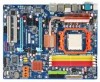
-MA790FX-DS5 Motherboard Layout KB_MS OPTICAL ATX_12V_2X CPU_FAN Socket AM2 COMA COAXIAL ATX V1394 USB_1394 PWR_FAN USB_LAN1 GA-MA790FX-DS5 DDRII_1 DDRII_2 DDRII_3 DDRII_4 USB_ESATA AUDIO RTL8111B F_AUDIO PCIE_1_1 NB_FAN AMD 790FX IDE FDD GIGABYTE SATA2 PCIE_1_2 PCIE_16_A AMD - Gigabyte GA-MA790FX-DS5 | Manual - Page 8
PCIe CLK (100 MHz) AMD Socket AM2+/AM2 CPU CPU CLK+/-(200 MHz) DDR2 1066/800/667 MHz DIMM Dual Channel Memory Hyper Transport 3.0 PCI Express x16 Bus 3 PCI Express x1 LAN RJ45 PCIe CLK (100 MHz) RTL8111B x1 PCI Express Bus 4 SATA 3Gb/s x1 GIGABYTE SATA2 x 2 AMD 790FX AMD SB600 PCI Bus - Gigabyte GA-MA790FX-DS5 | Manual - Page 9
's manual and follow these procedures: • Prior to installation, do not remove or break motherboard S/N wrist strap when handling electronic components such as a motherboard, CPU or memory. If you do not have an ESD wrist steps or have a problem related to the use of the product, please consult - Gigabyte GA-MA790FX-DS5 | Manual - Page 10
for the latest CPU support list.) 5200/2000 MT/s North Bridge: AMD 790FX South Bridge: AMD SB600 4 x 1.8V DDR2 DIMM sockets supporting up to 16 GB of system memory (Note 1) Dual channel memory architecture Support for DDR2 1066 (Note 2)/800/667 MHz memory modules (Go to GIGABYTE's website for the - Gigabyte GA-MA790FX-DS5 | Manual - Page 11
ATX 12V power connector Š 1 x 4-pin PCIe 12V power connector Š 1 x floppy disk drive connector Š 1 x IDE connector Š 6 x SATA 3Gb/s connectors Š 1 x CPU fan header Š 2 x system fan headers Š 1 x power fan header Š 1 x North Bridge fan header Š 1 x front panel header Š 1 x front panel audio - Gigabyte GA-MA790FX-DS5 | Manual - Page 12
ECC memory. (Note 4) Whether the CPU/system fan speed control function is supported will depend on the CPU/ system cooler you install. (Note 5) Available functions in Easytune may differ by motherboard model. (Note 6) The adjustable CPU voltage range depends on the CPU being used. GA-MA790FX-DS5 - Gigabyte GA-MA790FX-DS5 | Manual - Page 13
before you begin to install the CPU: • Make sure that the motherboard supports the CPU. (Go to GIGABYTE's website for the latest CPU support list.) • Always turn off the computer and unplug the power cord from the power outlet before installing the CPU to prevent hardware damage. • Locate the - Gigabyte GA-MA790FX-DS5 | Manual - Page 14
into its socket, place one finger down on the middle of the CPU, lowering the locking lever and latching it into the fully locked position. Do not force the CPU into the CPU socket. The CPU cannot fit in if oriented incorrectly. Adjust the CPU orientation if this occurs. GA-MA790FX-DS5 Motherboard - Gigabyte GA-MA790FX-DS5 | Manual - Page 15
lock into place. (Refer to your CPU cooler installation manual for instructions on installing the cooler.) Step 5: Finally, attach the power connector of the CPU cooler to the CPU fan header (CPU_FAN) on the motherboard. Use extreme care when removing the CPU cooler because the thermal grease/tape - Gigabyte GA-MA790FX-DS5 | Manual - Page 16
only one DDR2 memory module is installed. 2. When enabling Dual Channel mode with two or four memory modules, it is recommended that memory of the same capacity, brand, speed, and chips be used and installed in the same colored DDR2 sockets for optimum performance. GA-MA790FX-DS5 Motherboard - 16 - Gigabyte GA-MA790FX-DS5 | Manual - Page 17
to install DDR2 DIMMs on this motherboard. Notch DDR2 DIMM A DDR2 memory module has a notch, so it can only fit in one direction. Follow the steps below to correctly install your memory modules in the memory sockets. Step 1: Note the orientation of the memory module. Spread the retaining clips at - Gigabyte GA-MA790FX-DS5 | Manual - Page 18
expansion card: • Make sure the motherboard supports the expansion card. Carefully read the manual that came with your expansion card. necessary, go to BIOS Setup to make any required BIOS changes for your expansion card(s). 7. Install the driver provided with the GA-MA790FX-DS5 Motherboard - 18 - - Gigabyte GA-MA790FX-DS5 | Manual - Page 19
card straight up from the slot. You can also press the latch on the back of the white-drawable bar to release the card. • The motherboard provides a PCIE_12V power connector, which can supply extra power to the onboard PCI Express x16 slots. When you install two graphics cards, connect the power - Gigabyte GA-MA790FX-DS5 | Manual - Page 20
to a back panel connector, first remove the cable from your device and then remove it from the motherboard. • When removing the cable, pull it straight out from the connector. Do not rock it side to side to prevent an electrical short inside the cable connector. GA-MA790FX-DS5 Motherboard - 20 - - Gigabyte GA-MA790FX-DS5 | Manual - Page 21
to perform different functions via the audio software. Only microphones still MUST be connected to the default Mic in jack ( ). Refer to the instructions on setting up a 2/4/5.1/ 7.1-channel audio configuration in Chapter 5, "Configuring 2/4/5.1/7.1-Channel Audio." - 21 - Hardware Installation - Gigabyte GA-MA790FX-DS5 | Manual - Page 22
1-7 Internal Connectors 13 5 2 14 6 15 16 19 17 4 7 1) ATX_12V_2X 2) ATX 3) CPU_FAN 4) SYS_FAN1/SYS_FAN2 5) PWR_FAN 6) NB_FAN 7) PCIE_12V 8) FDD 9) IDE 10) SATAII0/1/2/3 11) GSATAII_1/ device cable has been securely attached to the connector on the motherboard. GA-MA790FX-DS5 Motherboard - 22 - - Gigabyte GA-MA790FX-DS5 | Manual - Page 23
ATX (2x4 12V Power Connector and 2x12 Main Power Connector) With the use of the power connector, the power supply can supply enough stable power to all the components on the motherboard . The 12V power connector mainly supplies power to the CPU. If the 12V power connector is not connected, the - Gigabyte GA-MA790FX-DS5 | Manual - Page 24
to the fan headers to prevent your CPU, North Bridge and system from overheating. Overheating may result in damage to the CPU/North Bridge or the system may hang. • These fan headers are not configuration jumper blocks. Do not place a jumper cap on the headers. GA-MA790FX-DS5 Motherboard - 24 - - Gigabyte GA-MA790FX-DS5 | Manual - Page 25
extra power to the PCI Express x16 slots on the motherboard. Connect the power supply cable to this connector when Drive Connector) This connector is used to connect a floppy disk drive. The types of floppy disk drives supported are: 360 KB, 720 KB, 1.2 MB, 1.44 MB, and 2.88 MB. Before connecting - Gigabyte GA-MA790FX-DS5 | Manual - Page 26
Each SATA connector supports a single SATA device. The AMD SB600 controller supports RAID 0, RAID 1 and RAID 0+1. Refer to Chapter 5, "Configuring SATA Hard Drive(s)," for instructions on configuring a and the total number of hard drives must be an even number. GA-MA790FX-DS5 Motherboard - 26 - - Gigabyte GA-MA790FX-DS5 | Manual - Page 27
and are compatible with SATA 1.5Gb/s standard. Each SATA connector supports a single SATA device. The GIGABYTE SATA2 controller supports RAID 0 and RAID 1. Refer to Chapter 5, "Configuring SATA Hard Drive(s)," for instructions on configuring a RAID array. Pin No. Definition 1 GND 2 TXP - Gigabyte GA-MA790FX-DS5 | Manual - Page 28
heard if no problem is detected at system startup. If a problem is detected, the BIOS may issue beeps in different patterns to indicate the problem. Refer to Chapter 5, "Troubleshooting," for information about and the pin assignments are matched correctly. GA-MA790FX-DS5 Motherboard - 28 - - Gigabyte GA-MA790FX-DS5 | Manual - Page 29
GND 10 NC • The front panel audio header supports HD audio by default. If your chassis provides an AC'97 front panel audio module, refer to the instructions on how to activate AC'97 functioninality via the audio software in Chapter 5, "Configuring 2/4/5.1/7.1-Channel Audio." • When using an AC'97 - Gigabyte GA-MA790FX-DS5 | Manual - Page 30
an HDMI display to the graphics card and have digital audio output from the HDMI display at the same time. For information about connecting the S/PDIF digital audio cable, carefully read the manual for your expansion card. Pin No. Definition 1 1 SPDIFO 2 GND GA-MA790FX-DS5 Motherboard - 30 - - Gigabyte GA-MA790FX-DS5 | Manual - Page 31
18) F_USB1/F_USB2 (USB Headers, Yellow) The headers conform to USB 2.0/1.1 specification. Each USB header can provide two USB ports via an optional USB bracket. For purchasing the optional USB bracket, please contact the local dealer. 10 9 2 1 Pin No. 1 2 3 4 5 6 7 8 9 10 Definition Power (5V) - Gigabyte GA-MA790FX-DS5 | Manual - Page 32
No Pin SLCT GND 21) BATTERY The battery provides power to keep the values (such as BIOS configurations, date, and time information) in the CMOS when the computer is turned off. Replace batteries must be handled in accordance with local environmental regulations. GA-MA790FX-DS5 Motherboard - 32 - - Gigabyte GA-MA790FX-DS5 | Manual - Page 33
the jumper. Failure to do so may cause damage to the motherboard. • After system restart, go to BIOS Setup to load factory defaults (select Load Optimized Defaults) or manually configure the BIOS settings (refer to Chapter 2, "BIOS Setup," for BIOS configurations). - 33 - Hardware Installation - Gigabyte GA-MA790FX-DS5 | Manual - Page 34
GA-MA790FX-DS5 Motherboard - 34 - - Gigabyte GA-MA790FX-DS5 | Manual - Page 35
latest version of BIOS from the Internet and updates the BIOS. For instructions on using the Q-Flash and @BIOS utilities, refer to Chapter 4, "BIOS Update Utilities." • Because BIOS flashing is potentially risky, if you do not encounter problems using the current version of BIOS, it is recommended - Gigabyte GA-MA790FX-DS5 | Manual - Page 36
Screen The following screen may appear when the computer boots. Motherboard Model BIOS Version Award Modular BIOS v6.00PG, An Energy Star Ally Copyright (C) 1984-2007, Award Software, Inc. GA-MA790FX-DS5 F1a . . . . : BIOS Setup : XpressRecovery2 : Boot Menu : Qflash 09/20 - Gigabyte GA-MA790FX-DS5 | Manual - Page 37
the Item Help block on the right (submenus only) Restore the previous BIOS settings for the current submenus Load the Fail-Safe BIOS default settings for the current submenus Load the Optimized BIOS default settings for the current submenus Access the Q-Flash utility - Gigabyte GA-MA790FX-DS5 | Manual - Page 38
your CPU, memory, BIOS Setup. (Pressing can also carry out this task.) „ Exit Without Saving Abandon all changes and the previous settings remain in effect. Pressing to the confirmation message will exit BIOS Setup. (Pressing can also carry out this task.) GA-MA790FX-DS5 Motherboard - Gigabyte GA-MA790FX-DS5 | Manual - Page 39
] Drive A Floppy 3 Mode Support [1.44M, 3.5"] [Disabled] Halt On [All, But Keyboard] KLJI: Move Enter: Select F5: Previous Values +/-/PU/PD: Value F10: Save F6: Fail-Safe Default ESC: Exit F1: General Help F7: Optimized Defaults Base Memory Extended Memory CMOS Setup Utility-Copyright - Gigabyte GA-MA790FX-DS5 | Manual - Page 40
: None, 360K/5.25", 1.2M/5.25", 720K/3.5", 1.44M/3.5", 2.88M/3.5". Floppy 3 Mode Support Allows you to specify whether the installed floppy disk drive is 3-mode floppy disk drive, a Japanese standard floppy disk drive. Options are: Disabled (default), Drive A. GA-MA790FX-DS5 Motherboard - 40 - - Gigabyte GA-MA790FX-DS5 | Manual - Page 41
boot will not stop for a keyboard or a floppy disk drive error but it will stop for all other errors. Memory These fields are read-only and are determined by the BIOS POST. Base Memory Also called conventional memory. Typically, 640 KB will be reserved for the MS-DOS operating system. Extended - Gigabyte GA-MA790FX-DS5 | Manual - Page 42
the password(s) under the Set Supervisor/User Password item in the BIOS Main Menu. Setup A password is only required for entering the BIOS Setup program. (Default) System A password is required for booting the system and for entering the BIOS Setup program. GA-MA790FX-DS5 Motherboard - 42 - - Gigabyte GA-MA790FX-DS5 | Manual - Page 43
card on the PCIE_16_A slot as the first display. PEG1 Sets the PCI Express graphics card on the PCIE_16_B slot as the first display. - 43 - BIOS Setup - Gigabyte GA-MA790FX-DS5 | Manual - Page 44
Onboard Audio Function Onboard 1394 Function OnChip USB Controller USB EHCI Controller USB Keyboard Support USB Mouse Support Legacy F1: General Help F7: Optimized Defaults OnChip IDE Channel0 Enables or disables the integrated IDE controller. (Default: Enabled) GA-MA790FX-DS5 Motherboard - 44 - - Gigabyte GA-MA790FX-DS5 | Manual - Page 45
SATA Type (AMD SB600 chip) you wish to install operating systems that support Native mode, e.g. Windows XP/2000. that allows the storage driver to enable advanced Serial -Safe Defaults ESC: Exit F1: General Help F7: Optimized Defaults Onboard LAN Function Enables or disables BIOS Setup - Gigabyte GA-MA790FX-DS5 | Manual - Page 46
Defaults ESC: Exit F1: General Help F7: Optimized Defaults This motherboard incorporates cable diagnostic feature designed to the LAN Boot ROM is activated. When a Cable Problem Occurs... If a cable problem occurs on a specified pair of wires, the Status field GA-MA790FX-DS5 Motherboard - 46 - - Gigabyte GA-MA790FX-DS5 | Manual - Page 47
driver to enable advanced Serial ATA features such as Native Command Queuing and hot plug. RAID Enables RAID for the SATA controller. Onboard Audio Function Enables or disables the onboard audio Support Allows USB keyboard to be used in MS-DOS. (Default: Disabled) USB Mouse Support Allows - Gigabyte GA-MA790FX-DS5 | Manual - Page 48
)(default), EPP (Enhanced Parallel Port), ECP (Extended Capabilities Port), ECP+EPP. ECP Mode Use DMA Selects DMA channel for the LPT port in ECP mode. This item is configurable only if Parallel Port Mode is set to ECP or ECP+EPP mode. Options are: 3 (default), 1. GA-MA790FX-DS5 Motherboard - 48 - - Gigabyte GA-MA790FX-DS5 | Manual - Page 49
from S3 PME Event Wake Up HPET Support (Note) Power On By Mouse ESC: Exit F1: General Help F7: Optimized Defaults ACPI Suspend Type Specifies to enter the ACPI S3 (Suspend to RAM) sleep state. In S3 sleep state, wake-up signal from a modem that supports wake-up function. (Default: Disabled) - Gigabyte GA-MA790FX-DS5 | Manual - Page 50
a PS/2 keyboard wake-up event. Note: you need an ATX power supply providing at least 1A on the +5VSB lead. turned on upon the return of the AC power. Memory The system returns to its last known awake state Supported on Windows® Vista® operating system only. GA-MA790FX-DS5 Motherboard - 50 - - Gigabyte GA-MA790FX-DS5 | Manual - Page 51
,14,15 PCI2 IRQ Assignment Auto 3,4,5,7,9,10,11,12,14,15 +/-/PU/PD: Value F10: Save F6: Fail-Safe Defaults ESC: Exit F1: General Help F7: Optimized Defaults BIOS auto-assigns IRQ to the first PCI slot. (Default) Assigns IRQ 3,4,5,7,9,10,11,12,14,15 to the first PCI slot - Gigabyte GA-MA790FX-DS5 | Manual - Page 52
Help F7: motherboard CI header. If the system chassis cover is removed, this field will show "Yes", otherwise it will show "No". To clear the chassis intrusion status record, set Reset Case Open Status to Enabled, save the settings to CMOS, and then restart your system. GA-MA790FX-DS5 Motherboard - Gigabyte GA-MA790FX-DS5 | Manual - Page 53
Smart FAN Control is set to Enabled. Auto Lets BIOS autodetect the type of CPU fan installed and sets the optimal CPU fan control mode. (Default) Voltage Sets Voltage mode for a 3-pin CPU fan. PWM Sets PWM mode for a 4-pin CPU fan. System Smart FAN Control Enables or disables the system - Gigabyte GA-MA790FX-DS5 | Manual - Page 54
to reset the board to default values. CPU Frequency (MHz) Allows you to manually set the CPU host frequency. The adjustable range is from 200 MHz to 500 MHz Important It is highly recommended that the CPU frequency be set in accordance with the CPU specifications. GA-MA790FX-DS5 Motherboard - 54 - - Gigabyte GA-MA790FX-DS5 | Manual - Page 55
set the frequency for the HT Link between the CPU and chipset. Auto lets BIOS automatically set the HT Link frequency as required. Options are: Auto (default), 200 MHz, 400 MHz, 600 MHz, 800 MHz, 1 GHz. PCIE Clock (MHz) Allows you to manually set the PCIe clock frequency. The adjustable range is - Gigabyte GA-MA790FX-DS5 | Manual - Page 56
Increases Chipset voltage by 0.05V to 0.40V at 0.05V increment. PCIE OverVoltage Control Allows you to to set PCIe voltage. Normal Supplies the PCIe bus voltage as required. (Default) +0.05V ~ +0.45V Increases PCIe bus voltage by 0.05V to 0.45V at 0.05V increment. GA-MA790FX-DS5 Motherboard - Gigabyte GA-MA790FX-DS5 | Manual - Page 57
. Normal Supplies the Hyper Transport Receive voltage as required. (Default) +0.05V ~ +0.45V Increases Hyper Transport Receive voltage by 0.05V to 0.45V at 0.05V increment. - 57 - BIOS Setup - Gigabyte GA-MA790FX-DS5 | Manual - Page 58
Press on this item and then press the key to load the optimal BIOS default settings. The BIOS defaults settings helps the system to operate in optimum state. Always load the Optimized defaults after updating the BIOS or after clearing the CMOS values. GA-MA790FX-DS5 Motherboard - 58 - - Gigabyte GA-MA790FX-DS5 | Manual - Page 59
Password Save & Exit Setup Exit Without Saving ESC: Quit F8: Q-Flash KLJI: Select Item F10: Save & Exit Setup F11: Save CMOS to BIOS F12: Load CMOS from BIOS Change/Set/Disable Password Press on this item and type the password with up to 8 characters and then press . You will be - Gigabyte GA-MA790FX-DS5 | Manual - Page 60
F11: Save CMOS to BIOS F12: Load CMOS from BIOS Abandon all Data Press on this item and press the key. This exits the BIOS Setup without saving the changes made in BIOS Setup to the CMOS. Press or to return to the BIOS Setup Main Menu. GA-MA790FX-DS5 Motherboard - 60 - - Gigabyte GA-MA790FX-DS5 | Manual - Page 61
other drivers. • After the drivers are installed, follow the onscreen instructions to restart your system. You can install other applications included in the motherboard driver disk. • For USB 2.0 driver support under the Windows XP operating system, please install the Windows XP Service Pack - Gigabyte GA-MA790FX-DS5 | Manual - Page 62
all the tools and applications that GIGABYTE develops and some free software. You may press the Install button following an item to install it. 3-3 Driver CD Information This page provides information about the drivers, applications and tools in this driver disk. GA-MA790FX-DS5 Motherboard - 62 - - Gigabyte GA-MA790FX-DS5 | Manual - Page 63
3-4 Hardware Information This page provides information about the hardware devices on this motherboard. 3-5 Contact Us Check the contacts information of the GIGABYTE headquarter in Taiwan and the overseas branch offices on the last page of this manual. - 63 - Drivers Installation - Gigabyte GA-MA790FX-DS5 | Manual - Page 64
GA-MA790FX-DS5 Motherboard - 64 - - Gigabyte GA-MA790FX-DS5 | Manual - Page 65
system data and perform restoration of it. Supporting NTFS, FAT32, and FAT16 file systems, your system soon after the operating system and drivers are installed. • The amount of data and hard Intel® x86 platform • At least 64 MB of system memory • VESA compatible graphics card • Windows® 2000 with SP3 - Gigabyte GA-MA790FX-DS5 | Manual - Page 66
Drive 1. Set CD-ROM drive as the first boot device under "Advanced BIOS Features" in the BIOS Setup program. Save the changes and exit. 2. When partitioning your hard drive for example, NTFS) and begin the installation of the operating system (Figure 3). Figure 3 GA-MA790FX-DS5 Motherboard - 66 - - Gigabyte GA-MA790FX-DS5 | Manual - Page 67
4. After the operating system is installed, right-click the My Computer icon on your desktop and select Manage (Figure 4). Go to Computer Management to check disk allocation. Xpress Recovery2 will save the backup file to the unallocated space (black stripe along the top)(Figure 5). Please note that - Gigabyte GA-MA790FX-DS5 | Manual - Page 68
from the motherboard driver disk to Award Modular BIOS v6.00PG, An Energy Star Ally Copyright (C) 1984-2007, Award Software, Inc. GA-MA790FX-DS5 F1a . . . . : BIOS Setup to check disk allocation. Figure 12 GA-MA790FX-DS5 Motherboard Xpress Recovery2 will automatically create a new partition to - Gigabyte GA-MA790FX-DS5 | Manual - Page 69
D. Using the Restore Function in Xpress Recovery2 Select RESTORE to restore the backup to your hard drive in case the system breaks down. The RESTORE option will not be present if no backup is created before (Figure 13, 14). Figure 13 Figure 14 E. Removing the Backup 1. If you wish to remove the - Gigabyte GA-MA790FX-DS5 | Manual - Page 70
. GA-MA790FX-DS5 F1a . . . . : BIOS Setup : XpressRecovery2 : Boot Menu : Qflash 09/20/2007-RD790-SB600-6A66AG02C-00 Because BIOS flashing is potentially risky, please do it with caution. Inadequate BIOS flashing may result in system malfunction. GA-MA790FX-DS5 Motherboard - 70 - Gigabyte GA-MA790FX-DS5 | Manual - Page 71
Update BIOS from Drive and press . • The Save Main BIOS to Drive option allows you to save the current BIOS file. • Q-Flash only supports USB BIOS update file and press . Make sure the BIOS update file matches your motherboard model. Step 2: The process of the system reading the BIOS - Gigabyte GA-MA790FX-DS5 | Manual - Page 72
Setup F11: Save CMOS to BIOS F12: Load CMOS from BIOS Load Optimized Defaults Press to load BIOS defaults Step 6: Select Save & Exit Setup and then press to save settings to CMOS and exit BIOS Setup. The procedure is complete after the system restarts. GA-MA790FX-DS5 Motherboard - 72 - - Gigabyte GA-MA790FX-DS5 | Manual - Page 73
and Using @BIOS: Use the motherboard driver disk included with the motherboard to install @BIOS. • Installing the @BIOS utility. • Accessing the @BIOS utility. Click Start>All Programs>GIGABYTE>@BIOS Select @BIOS and click Install. C. Options and Instructions: 1. Save the Current BIOS File In - Gigabyte GA-MA790FX-DS5 | Manual - Page 74
matches your motherboard model. Updating the BIOS with an incorrect BIOS file could result in an unbootable system. Step 4: As the system boots, press to enter the BIOS Setup program. Select Load Optimized Defaults and press to load BIOS defaults. GA-MA790FX-DS5 Motherboard - 74 - Gigabyte GA-MA790FX-DS5 | Manual - Page 75
the CPU frequency Shows the supported function(s) Go to GIGABYTE website to update EasyTune 5 Pro Opens EasyTune 5 Pro help file Quits or minimizes the EasyTune 5 Pro interface Performance Enhancement Incorrectly doing overclock/overvoltage may result in damage to CPU, chipset, or memory and - Gigabyte GA-MA790FX-DS5 | Manual - Page 76
. Click Apply and then OK to turn on ReadyBoost. • The USB flash drive must have at least 256 MB of space. • The recommended amount of memory to use for ReadyBoost acceleration is one to three times the amount of RAM installed in your computer. GA-MA790FX-DS5 Motherboard - 76 - - Gigabyte GA-MA790FX-DS5 | Manual - Page 77
An empty formatted floppy disk. • Windows Vista/XP/2000 setup disk. • Motherboard driver disk. 5-1-1 Configuring AMD SB600 SATA Controllers A. Installing SATA hard (For example, on this motherboard, the SATAII0, SATAII1, SATAII2 and SATAII3 ports are supported by AMD SB600 Southbridge.) Then connect - Gigabyte GA-MA790FX-DS5 | Manual - Page 78
F7: Optimized Defaults Step 2: Save changes and exit BIOS Setup. The BIOS Setup menus described in this section may differ from the exact settings for your motherboard. The actual BIOS Setup menu options you will see shall depend on the motherboard you have and the BIOS version. GA-MA790FX-DS5 - Gigabyte GA-MA790FX-DS5 | Manual - Page 79
C. Configuring RAID set in RAID BIOS Enter the RAID BIOS setup utility to configure a RAID array. Skip this step if you do not want to create RAID. Step 1: After the POST memory test begins and before the operating system boot begins, look for a message which says "Press to enter FastBuild - Gigabyte GA-MA790FX-DS5 | Manual - Page 80
Mode: WriteThru [ Drives Assignments] ] Channel:ID Drive Model 1:Mas WDC WD800JD-22LSA0 2:Mas WDC WD800JD-22LSA0 Capacity (MB) 80026 80026 Assignment N N [K] Up [L] Down [ Keys Available] ] [ESC] Exit [Space] Change Option Figure 5 [Ctrl-Y] Save GA-MA790FX-DS5 Motherboard - 80 - - Gigabyte GA-MA790FX-DS5 | Manual - Page 81
Main Menu and press again if you want to exit the RAID BIOS utility. View Drive Assignments The View Drive Assignments option in the Main Menu if unassigned. FastBuild (tm) Utility (c) 2006 ATI Technology, Inc. Channel:ID [ View Drives Assignments ] Drive Model Capacity (MB) 1:Mas WDC - Gigabyte GA-MA790FX-DS5 | Manual - Page 82
Block: 64KB Cache Mode: WriteThru [ Drives Assignments] ] Channel:ID Drive Model 1:Mas WDC WD800JD-22LSA0 2:Mas WDC WD800JD-22LSA0 Capacity (MB) 80026 80026 Are you sure you want to delete this array? Press Ctrl-Y to Delete, or others to abort... Figure 8 GA-MA790FX-DS5 Motherboard - 82 - - Gigabyte GA-MA790FX-DS5 | Manual - Page 83
to "Chapter 1," Hardware Installation," to identify the SATA controller for the SATA port. (For example, on this motherboard, the GSATAII_1, GSATAII_2 and eSATA ports are supported by GIGABYTE SATA2.) Then connect the power connector from your power supply to the hard drive. B. Configuring SATA - Gigabyte GA-MA790FX-DS5 | Manual - Page 84
: Exit F1: General Help F7: Optimized Defaults The BIOS Setup menus described in this section may differ from the exact settings for your motherboard. The actual BIOS Setup menu options you will see shall depend on the motherboard you have and the BIOS version. GA-MA790FX-DS5 Motherboard - 84 - - Gigabyte GA-MA790FX-DS5 | Manual - Page 85
memory test begins and before the operating system boot begins, look for a message which says "Press to enter RAID Setup Utility" (Figure 3). Press + to enter the GIGABYTE SATA2 RAID BIOS utility. GIGABYTE Non-RAID [ RAID Disk Drive List ] [IJTAB]-Switch Window [KL]-Select - Gigabyte GA-MA790FX-DS5 | Manual - Page 86
RAID drive to be identified by system BIOS or OS. [IJ]-Move Cursor [DEL List ] [ Help ] Select RAID Level RAID 0 RAID 1 JBOD - Data striped for performance Data mirrored for redundancy Data concatenated for huge temporarily disk required [KL]-Switch RAID Level GA-MA790FX-DS5 Motherboard - Gigabyte GA-MA790FX-DS5 | Manual - Page 87
Disks: After a RAID mode is selected, RAID BIOS automatically assigns the two hard drives installed as the 4 KB to 128 KB. Press . GIGABYTE Technology Corp. PCIE-to-SATAII/IDE RAID Controller BIOSv1.06.59 [ Create New RAID ] [ Hard Disk Drive List ] Name: GRAID Level: 0-Stripe Disks: - Gigabyte GA-MA790FX-DS5 | Manual - Page 88
key while in the Main Menu block to move the selection bar to the RAID Disk Drive List block. Select the array and press . A small window displaying the array information will appear in Switch Window [KL]-Select RAID [ENTER]-Detail Figure 10 [ESC]-Exit GA-MA790FX-DS5 Motherboard - 88 - - Gigabyte GA-MA790FX-DS5 | Manual - Page 89
BIOS utility, then press (Figure 11). GIGABYTE Technology Corp. PCIE-to-SATAII/IDE RAID Controller BIOSv1.06.59 [ Main Menu ] [ Hard Disk Drive List proceed to create the SATA RAID/AHCI driver diskette and the installation of the SATA RAID/AHCI driver and operating system. Delete the RAID - Gigabyte GA-MA790FX-DS5 | Manual - Page 90
users without a startup disk: Use an alternative system and insert the motherboard driver disk. From your optical drive folder, double click the MENU.exe file in the BootDrv folder (Figure 3). A command prompt window will open similar to that in Figure 2. GA-MA790FX-DS5 Motherboard Figure 3 - 90 - - Gigabyte GA-MA790FX-DS5 | Manual - Page 91
Now that you have prepared the SATA RAID/AHCI driver diskette and configured the required BIOS settings, you are ready to install Windows Vista/XP/2000 onto your hard drive(s). The following is an example of Windows XP and Vista installation. A. Installing Windows XP Step 1: Restart your system to - Gigabyte GA-MA790FX-DS5 | Manual - Page 92
correctly recognizes the AMD SB600 SATA RAID/AHCI driver in the support disks from a mass storage device manufacturer, or do not want to specify additional mass storage devices for use with Windows, press ENTER. S=Specify Additional Device ENTER=Continue F3=Exit Figure 4 GA-MA790FX-DS5 Motherboard - Gigabyte GA-MA790FX-DS5 | Manual - Page 93
the motherboard driver disk. When the screen as shown below appears, press to continue the driver installation from the floppy disk. The driver installation will be finished in about one minute. Windows Setup Setup will load support for the following mass storage device(s): GIGABYTE GBB363 - Gigabyte GA-MA790FX-DS5 | Manual - Page 94
Step 4: After the SATA RAID/AHCI driver installation is completed, you can proceed with the Windows XP installation. WindowsXP Professional Setup Welcome to , press R. To quit Setup without installing Windows XP, press F3. Enter= Continue R=Repair F3=Exit Figure 7 GA-MA790FX-DS5 Motherboard - 94 - - Gigabyte GA-MA790FX-DS5 | Manual - Page 95
exists in your system.) AMD SB600 SATA controllers: Step 1: Restart your system to boot from the Windows Vista setup disk and perform the motherboard driver disk into your system and browse to the following directory: \Chipset\RS690\Vista\Packages\Drivers\SBDrv\SB6xx\RAID\LH For Windows Vista - Gigabyte GA-MA790FX-DS5 | Manual - Page 96
as shown in Figure 10 appears, select AMD AHCI Compatible RAID Controller and press Next. Figure 10 Step 4: After the driver is loaded, the RAID drive will appear. Select the RAID drive and then press Next to continue the OS installation (Figure 11). Figure 11 GA-MA790FX-DS5 Motherboard - 96 - - Gigabyte GA-MA790FX-DS5 | Manual - Page 97
GIGABYTE SATA2 controllers: Step 1: Restart your system to boot from the Windows Vista setup disk and perform standard OS installation steps. When a screen similar to that below appears (RAID/AHCI hard drive(s) will not be detected at this stage), select Load Driver. (Figure 12). Figure 12 Step 2: - Gigabyte GA-MA790FX-DS5 | Manual - Page 98
14 appears, select GIGABYTE GBB36X Controller and press Next. Figure 14 Step 4: After the driver is loaded, select the RAID/AHCI drive(s) where you want to install the operating system and then press Next to continue the OS installation (Figure 15). Figure 15 GA-MA790FX-DS5 Motherboard - 98 - - Gigabyte GA-MA790FX-DS5 | Manual - Page 99
Before installing the audio driver, make sure the "Microsoft UAA Bus driver for High Definition Audio" has been installed from the motherboard driver disk and your operating system has been updated with the latest Service Pack for Windows. (Note) 2/4/5.1/7.1- Channel Audio Configurations: Refer to - Gigabyte GA-MA790FX-DS5 | Manual - Page 100
front panel jack detection check box. Click OK to activiate the AC'97 functionality. When using an AC'97 front panel audio module, you can only have audio signals present on either the front or the back panel audio connections, but not both at the same time. GA-MA790FX-DS5 Motherboard - 100 - - Gigabyte GA-MA790FX-DS5 | Manual - Page 101
In: The S/PDIF in jacks allow you to input digital audio signals to the computer for audio processing. A. Installing the S/PDIF In Cable: Step 1: First, attach the connector at the end of the cable to the SPDIF_IN header on your motherboard. Step 2: Secure the metal bracket to the chassis back - Gigabyte GA-MA790FX-DS5 | Manual - Page 102
audio signals. S/PDIF Coaxial Cable S/PDIF Optical Cable C. Configuring S/PDIF out: Click the tool icon in the DIGITAL section. In the S/PDIF In/Out Settings dialog box, select an output sampling rate and select (or disable) the output source. Click OK to complete the configuration. GA-MA790FX-DS5 - Gigabyte GA-MA790FX-DS5 | Manual - Page 103
effects. With DTS enabled, the system will transform two-channel stereo source material into multi-channel audio output, creating a virtual surround sound environment(Note). After installing the audio driver, at the center bottom of the Audio Control Panel, you should find the DTS control button as - Gigabyte GA-MA790FX-DS5 | Manual - Page 104
list, click Digital PCM Output. Enable this function to allow digital audio sources that are not digitally processed by DTS encoding to be output from the S/PDIF OUT. 5-2-4 Configuring Microphone Recording Step 1: After installing the audio driver, the Audio panel GA-MA790FX-DS5 Motherboard - 104 - - Gigabyte GA-MA790FX-DS5 | Manual - Page 105
to show and click OK to complete. Step 5: Next, while in Master Volume, go to Options and click Properties. In the Mixer device list, select Realtek HD Audio Input. Then set the recording sound level properly. Do NOT mute the recording sound, or you will not hear any sound when playing back - Gigabyte GA-MA790FX-DS5 | Manual - Page 106
the sound recording. 5-2-5 Using the Sound Recorder Recording the Sound: 1. Make sure you have connected the audio input device (e.g. microphone) to the computer. 2. On the File menu, choose New. 3. To record of a file or the Fast Backward button to the end. GA-MA790FX-DS5 Motherboard - 106 - - Gigabyte GA-MA790FX-DS5 | Manual - Page 107
5-3 Troubleshooting 5-3-1 Frequently Asked Questions To read more FAQs for your motherboard, please go to the Support\Motherboard\FAQ page on GIGABYTE's website. Q: In the BIOS Setup program, why are some BIOS options missing? A: Some advanced options are hidden in the BIOS Setup program. Press < - Gigabyte GA-MA790FX-DS5 | Manual - Page 108
insert the memory into the memory socket. The problem is verified and solved. Press to enter BIOS Setup. Select "Load Fail-Safe Defaults" (or "Load Optimized Defaults"). Select "Save & Exit Setup" to save changes and exit BIOS Setup. A (Continued...) GA-MA790FX-DS5 Motherboard - 108 - Gigabyte GA-MA790FX-DS5 | Manual - Page 109
CPU socket might fail. The problem is verified and solved. No The graphics card, expansion slot, or monitor might fail. The problem is verified and solved. Check if the keyboard is working properly. Yes Press to enter BIOS Setup. Select "Load Fail-Safe Defaults" (or "Load Optimized - Gigabyte GA-MA790FX-DS5 | Manual - Page 110
please contact your local government office, your household waste disposal service or where you purchased the product for details of environmentally the Customer Care number listed in your product's user's manual and we will be glad to help you with your effort. GA-MA790FX-DS5 Motherboard - 110 - - Gigabyte GA-MA790FX-DS5 | Manual - Page 111
Finally, we suggest that you practice other environmentally friendly actions by understanding and using the energy-saving features of this product (where applicable), recycling the inner and outer packaging (including shipping containers) this product was delivered in, and by disposing of or - Gigabyte GA-MA790FX-DS5 | Manual - Page 112
GA-MA790FX-DS5 Motherboard - 112 - - Gigabyte GA-MA790FX-DS5 | Manual - Page 113
- 113 - Appendix - Gigabyte GA-MA790FX-DS5 | Manual - Page 114
GA-MA790FX-DS5 Motherboard - 114 - - Gigabyte GA-MA790FX-DS5 | Manual - Page 115
(Soporte de habla hispano) FAX: +1-626-854-9339 Correo: [email protected] Tech. Support: http://rma.gigabyte-usa.com Web address: http://www.gigabyte.com.mx Singapore GIGA-BYTE SINGAPORE PTE. LTD. WEB address : http://www.gigabyte.sg Thailand WEB address : http://th.giga-byte.com Vietnam WEB - Gigabyte GA-MA790FX-DS5 | Manual - Page 116
language in the language list on the top right corner of the website. GIGABYTE Global Service System To submit a technical or non-technical (Sales/ Marketing) question, please link to : http://ggts.gigabyte.com.tw Then select your language to enter the system. GA-MA790FX-DS5 Motherboard - 116 -
-
 1
1 -
 2
2 -
 3
3 -
 4
4 -
 5
5 -
 6
6 -
 7
7 -
8
-
9
-
10
-
11
-
12
-
13
-
14
-
15
-
16
-
17
-
18
-
19
-
20
-
21
-
22
-
23
-
24
-
25
-
26
-
27
-
28
-
29
-
30
-
31
-
32
-
33
-
34
-
35
-
36
-
37
-
38
-
39
-
40
-
41
-
42
-
43
-
44
-
45
-
46
-
47
-
48
-
49
-
50
-
51
-
52
-
53
-
54
-
55
-
56
-
57
-
58
-
59
-
60
-
61
-
62
-
63
-
64
-
65
-
66
-
67
-
68
-
69
-
70
-
71
-
72
-
73
-
74
-
75
-
76
-
77
-
78
-
79
-
80
-
81
-
82
-
83
-
84
-
85
-
86
-
87
-
88
-
89
-
90
-
91
-
92
-
93
-
94
-
95
-
96
-
97
-
98
-
99
-
100
-
101
-
102
-
103
-
104
-
105
-
106
-
107
-
108
-
109
-
110
-
111
-
112
-
113
-
114
-
115
-
116
 |
 |

GA-MA790FX-DS5
AM2+/AM2 socket motherboard for
AMD Phenom
TM
FX processor/
AMD Phenom
TM
processor/
AMD Athlon
TM
64 FX processor/
AMD Athlon
TM
64 X2 Dual-Core processor/
AMD Athlon
TM
64 processor/AMD Sempron
TM
processor
User's Manual
Rev. 1003
12ME-MA79FX5-1003R