Gigabyte GA-MA790X-UD4P Manual
Gigabyte GA-MA790X-UD4P Manual
 |
UPC - 818313007513
View all Gigabyte GA-MA790X-UD4P manuals
Add to My Manuals
Save this manual to your list of manuals |
Gigabyte GA-MA790X-UD4P manual content summary:
- Gigabyte GA-MA790X-UD4P | Manual - Page 1
GA-MA790X-UD4P AM2+/AM2 socket motherboard for AMD PhenomTM II X3 processor/AMD PhenomTM II X4 processor/ AMD PhenomTM FX processor/AMD PhenomTM X4 processor/ AMD PhenomTM X3 processor/AMD AthlonTM X2 processor/ AMD AthlonTM processor/AMD SempronTM X2 processor/ AMD SempronTM processor User's Manual - Gigabyte GA-MA790X-UD4P | Manual - Page 2
Motherboard GA-MA790X-UD4P Apr. 30, 2009 Motherboard GA-MA790X-UD4P Apr. 30, 2009 - Gigabyte GA-MA790X-UD4P | Manual - Page 3
, read the Quick Installation Guide included with the product. For detailed product information, carefully read the User's Manual. For instructions on how to use GIGABYTE's unique features, read or download the information on/from the Support\Motherboard\Technology Guide page on our website - Gigabyte GA-MA790X-UD4P | Manual - Page 4
...6 GA-MA790X-UD4P Motherboard Layout 7 Block Diagram ...8 Chapter 1 Hardware Installation 9 1-1 Installation Precautions 9 1-2 Product Specifications 10 1-3 Installing the CPU and CPU Cooler 13 1-3-1 Installing the CPU 13 1-3-2 Installing the CPU Cooler 15 1-4 Installing the Memory 16 - Gigabyte GA-MA790X-UD4P | Manual - Page 5
Chapter 3 Drivers Installation 59 3-1 Installing Chipset Drivers 59 3-2 Application Software 60 3-3 Technical Manuals 60 3-4 Contact ...61 3-5 System ...61 3-6 Download Center 62 Chapter 4 Unique Features 63 4-1 Xpress Recovery2 63 4-2 BIOS Update Utilities 66 4-2-1 Updating the BIOS with - Gigabyte GA-MA790X-UD4P | Manual - Page 6
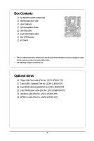
Box Contents GA-MA790X-UD4P motherboard Motherboard driver disk User's Manual Quick Installation Guide One IDE cable Four SATA 3Gb/s cables One SATA bracket I/O Shield • The box contents above are for reference only and the actual items shall depend - Gigabyte GA-MA790X-UD4P | Manual - Page 7
ATX R_USB Socket AM2 USB_1394_1 USB_1394 PWR_FAN USB IT8720 LAN AUDIO F_AUDIO PCIEX1_1 RTL8111C/D(L) PCIEX16_1 PCIEX1_2 CD_IN CODEC PCIEX1_3 SPDIF_IN SPDIF_OUT PCIEX8_1 PCI1 PCI2 COM FDD CI DDR2_1 DDR2_2 DDR2_3 DDR2_4 AMD 790X IDE GA-MA790X-UD4P CLR_CMOS BATTERY AMD SB750 - Gigabyte GA-MA790X-UD4P | Manual - Page 8
AM3/AM2+/AM2 CPU CPU CLK+/-(200 MHz) DDR2 1333(O.C.)/1066(Note 2)/800 MHz Hyper Transport 3.0 Dual Channel Memory Switch PCI Express Bus PCI Express Bus x1 x1 x1 x1 PCIe CLK (100 MHz) 3 PCI Express x1 RJ45 RTL8111C/D(L) LAN 2 SATA 3Gb/s PCI Bus GIGABYTE SATA2 TSB43AB23 AMD 790X AMD SB750 - Gigabyte GA-MA790X-UD4P | Manual - Page 9
to installing the motherboard, please have it on top of an antistatic pad or within an electrostatic shielding container. • Before unplugging the power supply cable from the motherboard, make sure the power supply has been turned off. • Before turning on the power, make sure the power supply voltage - Gigabyte GA-MA790X-UD4P | Manual - Page 10
(Go to GIGABYTE's website for the latest CPU support list.) 5200/2000 MT/s North Bridge: AMD 790X South Bridge: AMD SB750 4 x 1.8V DDR2 DIMM sockets supporting up to 16 GB of system memory (Note 1) Dual channel memory architecture Support for DDR2 1333(O.C.)/1066 (Note 2)/800 MHz memory modules (Go - Gigabyte GA-MA790X-UD4P | Manual - Page 11
1 x 24-pin ATX main power connector 1 x 8-pin ATX 12V power connector 1 x floppy disk drive connector 1 x IDE connector 8 x SATA 3Gb/s connectors 1 x CPU fan header 2 x system fan header 1 x power fan header 1 x front panel header 1 x front panel audio header 1 x CD - Gigabyte GA-MA790X-UD4P | Manual - Page 12
depend on the CPU/ system cooler you install. (Note 5) Available functions in EasyTune may differ by motherboard model. (Note 6) Due to the hardware limitation, you must install the AMD AM3 PhenomTM II/AM2+ PhenomTM Series CPU toenable support for Easy Energy Saver. GA-MA790X-UD4P Motherboard - 12 - Gigabyte GA-MA790X-UD4P | Manual - Page 13
guidelines before you begin to install the CPU: • Make sure that the motherboard supports the CPU. (Go to GIGABYTE's website for the latest CPU support list.) • Always turn off the computer and unplug the power cord from the power outlet before installing the CPU to prevent hardware damage. • Locate - Gigabyte GA-MA790X-UD4P | Manual - Page 14
socket, place one finger down on the middle of the CPU, lowering the locking lever and latching it into the fully locked position. Do not force the CPU into the CPU socket. The CPU cannot fit in if oriented incorrectly. Adjust the CPU orientation if this occurs. GA-MA790X-UD4P Motherboard - 14 - - Gigabyte GA-MA790X-UD4P | Manual - Page 15
lock into place. (Refer to your CPU cooler installation manual for instructions on installing the cooler.) Step 5: Finally, attach the power connector of the CPU cooler to the CPU fan header (CPU_FAN) on the motherboard. Use extreme care when removing the CPU cooler because the thermal grease/tape - Gigabyte GA-MA790X-UD4P | Manual - Page 16
only one DDR2 memory module is installed. 2. When enabling Dual Channel mode with two or four memory modules, it is recommended that memory of the same capacity, brand, speed, and chips be used and installed in the same colored DDR2 sockets for optimum performance. GA-MA790X-UD4P Motherboard - 16 - Gigabyte GA-MA790X-UD4P | Manual - Page 17
, make sure to turn off the computer and unplug the power cord from the power outlet to prevent damage to the memory module. DDR2 DIMMs are not compatible to DDR DIMMs. Be sure to install DDR2 DIMMs on this motherboard. Notch DDR2 DIMM A DDR2 memory module has a notch, so it can only fit in one - Gigabyte GA-MA790X-UD4P | Manual - Page 18
install an expansion card: • Make sure the motherboard supports the expansion card. Carefully read the manual that came with your expansion card. • Always turn off the computer and unplug the power cord from the power outlet before installing out from the slot. GA-MA790X-UD4P Motherboard - 18 - • - Gigabyte GA-MA790X-UD4P | Manual - Page 19
components in your system. We recommend a power supply that provides at least 20A 12V current. The exact power requirements depend on your overall system configurations. B. Supported Operating Systems: Windows Vista and Windows XP. C. BIOS Settings: Before configuring your system for CrossFireX - Gigabyte GA-MA790X-UD4P | Manual - Page 20
ends of the SATA signal cable and SATA power cable to your SATA device. For SATA device in external enclosure, you only need to connect the SATA signal cable. Before connecting the SATA signal cable, make sure to turn off the power of the external enclosure. GA-MA790X-UD4P Motherboard - 20 - - Gigabyte GA-MA790X-UD4P | Manual - Page 21
audio out to an external audio system that supports digital coaxial audio. Before using this feature, ensure that your audio system provides a coaxial digital audio remove the cable from your device and then remove it from the motherboard. • When removing the cable, pull it straight out from the - Gigabyte GA-MA790X-UD4P | Manual - Page 22
perform different functions via the audio software. Only microphones still MUST be connected to the default Mic in jack ( ). Refer to the instructions on setting up a 2/4/5.1/ 7.1-channel audio configuration in Chapter 5, "Configuring 2/4/5.1/7.1-Channel Audio." GA-MA790X-UD4P Motherboard - 22 - - Gigabyte GA-MA790X-UD4P | Manual - Page 23
16 4 11 4 1) ATX_12V_2X4 2) ATX 3) CPU_FAN 4) SYS_FAN1/SYS_FAN2 5) PWR_FAN power cord from the power outlet to prevent damage to the devices. • After installing the device and before turning on the computer, make sure the device cable has been securely attached to the connector on the motherboard - Gigabyte GA-MA790X-UD4P | Manual - Page 24
16 GND 17 +5V 18 GND 19 Power Good 20 5V SB(stand by +5V) 21 +12V 22 +12V(Onlyfor2x12-pinATX) 23 3.3V(Onlyfor2x12-pinATX) 24 Definition 3.3V -12V GND PS_ON(soft On/Off) GND GND GND -5V +5V +5V +5V (Only for 2x12-pin ATX) GND (Only for 2x12-pin ATX) GA-MA790X-UD4P Motherboard - 24 - - Gigabyte GA-MA790X-UD4P | Manual - Page 25
orientation (the black connector wire is the ground wire). The motherboard supports CPU fan speed control, which requires the use of a CPU fan with fan speed control design. For optimum heat dissipation, it is recommended that a system fan be installed inside the chassis. 1 CPU_FAN CPU_FAN: Pin No - Gigabyte GA-MA790X-UD4P | Manual - Page 26
number. • A RAID 5 configuration requires at least three hard drives. (The total number of hard drives does not have to be an even number.) • A RAID 10 configuration requires at least four hard drives and the total number of hard drives must be an even number. GA-MA790X-UD4P Motherboard - 26 - - Gigabyte GA-MA790X-UD4P | Manual - Page 27
supports a single SATA device. The GIGABYTE SATA2 controller supports RAID 0 and RAID 1. Refer to Chapter 5, "Configuring SATA Hard Drive(s)," for instructions on configuring a RAID when the system is in S3/S4 sleep state or powered off (S5). Pin No. Definition 1 MPD+ 2 MPD- 3 MPD- 1 - Gigabyte GA-MA790X-UD4P | Manual - Page 28
. A front panel module mainly consists of power switch, reset switch, power LED, hard drive activity LED, speaker and etc. When connecting your chassis front panel module to this header, make sure the wire assignments and the pin assignments are matched correctly. GA-MA790X-UD4P Motherboard - 28 - - Gigabyte GA-MA790X-UD4P | Manual - Page 29
• The front panel audio header supports HD audio by default. If your chassis provides an AC'97 front panel audio module, refer to the instructions on how to activate AC'97 functioninality via the audio software in Chapter 5, "Configuring 2/4/5.1/7.1-Channel Audio." • Audio signals will be present - Gigabyte GA-MA790X-UD4P | Manual - Page 30
an HDMI display to the graphics card and have digital audio output from the HDMI display at the same time. For information about connecting the S/PDIF digital audio cable, carefully read the manual for your expansion card. Pin No. Definition 1 SPDIFO 1 2 GND GA-MA790X-UD4P Motherboard - 30 - - Gigabyte GA-MA790X-UD4P | Manual - Page 31
NC • Do not plug the IEEE 1394 bracket (2x5-pin) cable into the USB header. • Prior to installing the USB bracket, be sure to turn off your computer and unplug the power cord from the power outlet to prevent damage to the USB bracket. 17) F_1394 (IEEE 1394a Header) The header conforms to - Gigabyte GA-MA790X-UD4P | Manual - Page 32
No Pin 19) CI (Chassis Intrusion Header) This motherboard provides a chassis detection feature that detects if the chassis cover has been removed. This function requires a chassis with chassis intrusion detection design. Pin No. Definition 1 Signal 1 2 GND GA-MA790X-UD4P Motherboard - 32 - - Gigabyte GA-MA790X-UD4P | Manual - Page 33
power cord from the power outlet before clearing the CMOS values. • After clearing the CMOS values and before turning on your computer, be sure to remove the jumper cap from the jumper. Failure to do so may cause damage to the motherboard. • After system restart, go to BIOS When installing the - Gigabyte GA-MA790X-UD4P | Manual - Page 34
GA-MA790X-UD4P Motherboard - 34 - - Gigabyte GA-MA790X-UD4P | Manual - Page 35
that searches and downloads the latest version of BIOS from the Internet and updates the BIOS. For instructions on using the Q-Flash and @BIOS utilities, refer to Chapter 4, "BIOS Update Utilities." • Because BIOS flashing is potentially risky, if you do not encounter problems using the current - Gigabyte GA-MA790X-UD4P | Manual - Page 36
POST Screen Motherboard Model BIOS Version Award Modular BIOS v6.00PG, An Energy Star Ally Copyright (C) 1984-2009, Award Software, Inc. GA-MA790X-UD4P E3 . . . . Function Keys : BIOS Setup : XpressRecovery2 : Boot Menu : Qflash 01/23/2009-RD790-SB750-7A66AG08C-00 Function - Gigabyte GA-MA790X-UD4P | Manual - Page 37
to accept or enter a sub-menu. (Sample BIOS Version: E3) CMOS Setup Utility-Copyright (C) 1984-2009 Award Software MB Intelligent Tweaker(M.I.T.) Standard CMOS Features Advanced BIOS Features Integrated Peripherals Power Management Setup PC Health Status Load Fail-Safe Defaults - Gigabyte GA-MA790X-UD4P | Manual - Page 38
the CMOS and exit BIOS Setup. (Pressing can also carry out this task.) Exit Without Saving Abandon all changes and the previous settings remain in effect. Pressing to the confirmation message will exit BIOS Setup. (Pressing can also carry out this task.) GA-MA790X-UD4P Motherboard - Gigabyte GA-MA790X-UD4P | Manual - Page 39
) allows BIOS to automatically adjust the CPU host frequency. Manual allows the CPU Frequency (Mhz) item below to be configurable. Note: If your system fails to boot after overclocking, please wait for 20 seconds to allow for automated system reboot, or clear the CMOS values to reset the board - Gigabyte GA-MA790X-UD4P | Manual - Page 40
Sets Memory Clock to X4.00. X5.33 Sets Memory Clock to X5.33. When you use a AM3 CPU: X2.00 Sets Memory Clock to X2.00. X2.66 Sets Memory Clock to X2.66. X3.33 Sets Memory Clock to X3.33. X4.00 Sets Memory Clock to X4.00. X5.33 Sets Memory Clock to X5.33. GA-MA790X-UD4P Motherboard - Gigabyte GA-MA790X-UD4P | Manual - Page 41
RAS Delay CMOS Setup Utility- memory control mode to two single-channel.(default) DDRII Timing Items Manual allows all DDRII Timing items below to be configurable. Options are: Auto (default), Manual. (Note) This item is present only if you install a CPU that supports this feature. - 41 - BIOS - Gigabyte GA-MA790X-UD4P | Manual - Page 42
all voltage control items below to be configurable. (Default: Auto) DDR2 Voltage Control Allows you to set memory voltage. Normal Supplies the memory voltage as required. (Default) +0.100V ~ +0.600V Increases memory voltage by 0.100V to 0.600V at 0.100V increment. GA-MA790X-UD4P Motherboard - Gigabyte GA-MA790X-UD4P | Manual - Page 43
being installed. (Default: Normal) Note: Increasing CPU voltage may result in damage to your CPU or reduce the useful life of the CPU. Normal CPU Vcore Displays the normal operating voltage of your CPU. (Note) This item is present only if you install a CPU that supports this feature. - 43 - BIOS - Gigabyte GA-MA790X-UD4P | Manual - Page 44
Software Standard CMOS Features Date Floppy 3 Mode Support [1.44M, 3.5"] [Disabled] Halt On [All, But Keyboard] Base Memory Extended Memory Move Enter: Select of the two methods below: • Auto Lets BIOS automatically detect IDE/SATA devices during the POST. GA-MA790X-UD4P Motherboard - 44 - - Gigabyte GA-MA790X-UD4P | Manual - Page 45
720K/3.5", 1.44M/3.5", 2.88M/3.5". Floppy 3 Mode Support Allows you to specify whether the installed floppy disk drive is 3-mode floppy disk drive Memory it will stop for all other errors. These fields are read-only and are determined by the BIOS POST. Base Memory Also called conventional memory - Gigabyte GA-MA790X-UD4P | Manual - Page 46
the password(s) under the Set Supervisor/User Password item in the BIOS Main Menu. Setup A password is only required for entering the BIOS Setup program. (Default) System A password is required for booting the system and for entering the BIOS Setup program. GA-MA790X-UD4P Motherboard - 46 - - Gigabyte GA-MA790X-UD4P | Manual - Page 47
perform unattended tasks while in a low-power mode that appears off (Default: Disabled) Full Screen LOGO GIGABYTE Logo at system startup. Disabled displays normal POST message. (Default: Enabled) Init Display First Specifies the first initiation of the monitor display from the installed BIOS Setup - Gigabyte GA-MA790X-UD4P | Manual - Page 48
Type The mode depends on the OnChip SATA Type settings. Onboard Audio Function Enables or disables the onboard audio function. (Default: Auto) If you wish to install a 3rd party add-in audio card instead of using the onboard audio, set this item to Disabled. GA-MA790X-UD4P Motherboard - 48 - - Gigabyte GA-MA790X-UD4P | Manual - Page 49
mode. Advanced Host Controller Interface (AHCI) is an interface specification that allows the storage driver to enable advanced Serial ATA features such as Native Command Queuing and hot plug. RAID Enables RAID for the SATA controller. Onboard LAN Function Enables or disables the onboard LAN - Gigabyte GA-MA790X-UD4P | Manual - Page 50
when the LAN Boot ROM is activated. When a Cable Problem Occurs... If a cable problem occurs on a specified pair of wires, the Status field Enabled) USB Keyboard Support Allows USB keyboard to be used in MS-DOS. (Default: Enabled) USB Mouse Support Allows USB mouse GA-MA790X-UD4P Motherboard - 50 - - Gigabyte GA-MA790X-UD4P | Manual - Page 51
signal from the installed USB device. (Default: Enabled) Modem Ring Resume Allows the system to be awakened from an ACPI sleep state by a wake-up signal from a modem that supports wake-up function. (Default: Disabled) (Note) Supported on Windows® Vista® operating system only. - 51 - BIOS Setup - Gigabyte GA-MA790X-UD4P | Manual - Page 52
an ATX power supply providing at powered on automatically. Note: When using this function, avoid inadequate shutdown from the operating system or removal of the AC power, or the settings may not be effective. (Note) Supported on Windows® Vista® operating system only. GA-MA790X-UD4P Motherboard - Gigabyte GA-MA790X-UD4P | Manual - Page 53
Status CMOS Setup Utility-Copyright (C) 1984-2009 Award Software PC Health Status Reset Case Open Status Case Opened Vcore DDR2 1.8V +3.3V +12V Current System Temperature Current CPU Temperature Current CPU FAN Speed Current SYSTEM FAN1 Speed Current SYSTEM FAN2 Speed Current POWER FAN Speed CPU - Gigabyte GA-MA790X-UD4P | Manual - Page 54
system fan speed control function. Enabled allows the system fan to run at different speed according to the system temperature. You can adjust the fan speed with EasyTune based on system requirements. If disabled, system fan runs at full speed. (Default: Enabled) GA-MA790X-UD4P Motherboard - 54 - Gigabyte GA-MA790X-UD4P | Manual - Page 55
Save CMOS to BIOS F12: Load CMOS from BIOS Press on this item and then press the key to load the optimal BIOS default settings. The BIOS defaults settings helps the system to operate in optimum state. Always load the Optimized defaults after updating the BIOS or after clearing the CMOS - Gigabyte GA-MA790X-UD4P | Manual - Page 56
you to view the BIOS settings but not to make changes. To clear the password, press on the password item and when requested for the password, press again. The message "PASSWORD DISABLED" will appear, indicating the password has been cancelled. GA-MA790X-UD4P Motherboard - 56 - - Gigabyte GA-MA790X-UD4P | Manual - Page 57
Supervisor Password Save to CMOS and EXIT (Y/N)? Y Set User Password Power Management Setup Save & Exit Setup PC Health Status Exit Without Saving ESC: Quit F8: Q-Flash Select Item F10: Save & Exit Setup Save Data to CMOS F11: Save CMOS to BIOS F12: Load CMOS from BIOS Press on - Gigabyte GA-MA790X-UD4P | Manual - Page 58
GA-MA790X-UD4P Motherboard - 58 - - Gigabyte GA-MA790X-UD4P | Manual - Page 59
to install other drivers. • After the drivers are installed, follow the onscreen instructions to restart your system. You can install other applications included in the motherboard driver disk. • For USB 2.0 driver support under the Windows XP operating system, please install the Windows XP Service - Gigabyte GA-MA790X-UD4P | Manual - Page 60
that GIGABYTE develops and some free software. You can click the Install button on the right of an item to install it. 3-3 Technical Manuals This page provides GIGABYTE's application guides, content descriptions for this driver disk, and the motherboard manuals. GA-MA790X-UD4P Motherboard - 60 - Gigabyte GA-MA790X-UD4P | Manual - Page 61
3-4 Contact For the detailed contact information of the GIGABYTE Taiwan headquarter or worldwide branch of fices, click the URL on this page to link to the GIGABYTE Website. 3-5 System This page provides the basic system information. - 61 - Drivers Installation - Gigabyte GA-MA790X-UD4P | Manual - Page 62
3-6 Download Center To update the BIOS, drivers, or applications, click the Download Center button to link to the GIGABYTE Web site. The latest version of the BIOS, drivers, or applications will be displayed. GA-MA790X-UD4P Motherboard - 62 - - Gigabyte GA-MA790X-UD4P | Manual - Page 63
is recommended to back up your system soon after the operating system and drivers are installed. • The amount of data and hard drive access speed may affect the • USB hard drives are not supported. • Hard drives in RAID/AHCI mode are not supported. Installation and Configuration Turn on your system - Gigabyte GA-MA790X-UD4P | Manual - Page 64
data) and begin the installation of the operating system. Step 4: After the operating system is installed, rightclick the Computer file. B. Accessing Xpress Recovery2 1. Boot from the motherboard driver disk to access Xpress Recovery2 for the first time. When . GA-MA790X-UD4P Motherboard - 64 - - Gigabyte GA-MA790X-UD4P | Manual - Page 65
D. Using the Restore Function in Xpress Recovery2 Select RESTORE to restore the backup to your hard drive in case the system breaks down. The RESTORE option will not be present if no backup is created before. E. Removing the Backup Step 1: If you wish to remove the backup file, select REMOVE. F. - Gigabyte GA-MA790X-UD4P | Manual - Page 66
, if the BIOS update file is saved to a hard drive in RAID/AHCI mode or a hard drive attached to an independent IDE/SA TA controller, use the key during the POST to access Q-Flash. Award Modular BIOS v6.00PG, An Energy Star Ally Copyright (C) 1984-2009, Award Software, Inc. GA-MA790X-UD4P E3 - Gigabyte GA-MA790X-UD4P | Manual - Page 67
HDD 0-0 Keep DMI Data Enable Update BIOS from Drive Sa0vefilBeI(Os)SfotounDdrive :Move ESC:Reset :Power Off Total size : 0 Free size : 0 3. Select the BIOS update file and press . Make sure the BIOS update file matches your motherboard model. Step 2: The process - Gigabyte GA-MA790X-UD4P | Manual - Page 68
Setup Load Optimized Defaults F11: Save CMOS to BIOS F12: Load CMOS from BIOS Press to load BIOS defaults Step 6: Select Save & Exit Setup and then press to save settings to CMOS and exit BIOS Setup. The procedure is complete after the system restarts. GA-MA790X-UD4P Motherboard - 68 - - Gigabyte GA-MA790X-UD4P | Manual - Page 69
location and then download the BIOS file that matches your motherboard model. Follow the on- screen instructions to complete. If the BIOS update file for your motherboard is not present on the @BIOS server site, please manually download the BIOS update file from GIGABYTE's website and follow - Gigabyte GA-MA790X-UD4P | Manual - Page 70
hardware components such as CPU, chipset, and memory and reduce the useful life of these components. Before you do the overclock/overvoltage, make sure that you fully know each function of EasyTune 6, or system instability or other unexpected results may occur. GA-MA790X-UD4P Motherboard - 70 - - Gigabyte GA-MA790X-UD4P | Manual - Page 71
will continue to run in taskbar) 14 INFO/Help 15 Live Utility Update (Check for the latest utility version) • The above data is for reference only. Actual performance may vary depending on motherboard model. • CPU Power and Power Scores are for reference only. Actual results may vary based on - Gigabyte GA-MA790X-UD4P | Manual - Page 72
of power saved will be recorded until re-activated when only the Easy Energy Saver is under the enable status, and power savings meter is unable to reset to zero. (Note 5) Easy Energy Saver Meter will automatically reset when the total power saving reaches 99999999 Watts. GA-MA790X-UD4P Motherboard - Gigabyte GA-MA790X-UD4P | Manual - Page 73
resources. Directions for using Q-Share After installing Q-Share from the motherboard driver disk, go to Start>All Programs>GIGABYTE> Q-Share.exe to launch the shared data folder Changes the data folder to be shared (Note) Updates Q-Share online Displays the current Q-Share version Exits Q-Share ( - Gigabyte GA-MA790X-UD4P | Manual - Page 74
the Microsoft Volume Shadow Copy Services technology, Time Repair allows you to quickly back up and restore your system data in the Windows Vista operating system. Time Repair supports NTFS file system and can so you cannot edit the contents of a shadow copy. GA-MA790X-UD4P Motherboard - 74 - - Gigabyte GA-MA790X-UD4P | Manual - Page 75
. (For example, on this motherboard, the SA TA2_0, SATA2_1, SATA2_2, SATA2_3, SATA2_4 and SA TA2_5 ports are supported by AMD SB750 South Bridge.) Then connect the power connector from your power supply to the hard drive. (Note 1) Skip this step if you do not want to create RAID array on the SA TA - Gigabyte GA-MA790X-UD4P | Manual - Page 76
Step 2: Save changes and exit BIOS Setup. The BIOS Setup menus described in this section may differ from the exact settings for your motherboard. The actual BIOS Setup menu options you will see shall depend on the motherboard you have and the BIOS version. GA-MA790X-UD4P Motherboard - 76 - - Gigabyte GA-MA790X-UD4P | Manual - Page 77
C. Configuring RAID set in RAID BIOS Enter the RAID BIOS setup utility to configure a RAID array. Skip this step if you do not want to create RAID. Step 1: After the POST memory test begins and before the operating system boot begins, look for a message which says "Press to enter FastBuild - Gigabyte GA-MA790X-UD4P | Manual - Page 78
of manually defining the drive elements and RAID levels for one or multiple disk arrays attached to the AMD SB750 controller. LD No RAID Mode [ Define LD Menu ] Total Drv LD 1 RAID 0 0 Stripe Block: 64 KB Gigabyte Boundary: ON ] Page Change Figure 5 GA-MA790X-UD4P Motherboard - 78 - - Gigabyte GA-MA790X-UD4P | Manual - Page 79
any other key to ignore this option> Figure 6 6. Press + to clear the MBR or press other keys to ignore this option. Then, the window RAID BIOS utility. View Drive Assignments The View Drive Assignments option in the Main Menu displays whether drives attached to the AMD SB750 controller - Gigabyte GA-MA790X-UD4P | Manual - Page 80
2008 Advanced Micro Devices, Inc. LD No [ View LD Definition Menu ] RAID Mode Total Drv Capacity (GB) Status LD 1 RAID 0 2 157.99 Functional Stripe Block: 64KB Cache Mode: WriteThru [ Drives in the disk! or press any other key to abort... Figure 9 GA-MA790X-UD4P Motherboard - 80 - - Gigabyte GA-MA790X-UD4P | Manual - Page 81
port on the motherboard. On this motherboard, the GSATA2_0 and GSATA2_1 ports are supported by the GIGABYTE SATA2 SATA controller.) Then connect the power connector from your power supply to the hard drive. B. Enabling the SATA controllers and configuring hard drive mode in BIOS Setup Make sure - Gigabyte GA-MA790X-UD4P | Manual - Page 82
[ RAID Disk Drive List ] [TAB]-Switch Window []-Select ITEM [ENTER]-Action Figure 3 [ESC]-Exit Note: In the main screen, you can select a hard drive in the Hard Disk Drive List block and press to see detailed information about the selected hard drive. GA-MA790X-UD4P Motherboard - Gigabyte GA-MA790X-UD4P | Manual - Page 83
In the main screen, press on the Create RAID Disk Drive item. Then the Create New RAID screen appears (Figure 4). GIGABYTE Technology Corp. PCIE-to-SATAII/IDE RAID Controller BIOS v1.06.59 [ Create New RAID ] [ Hard Disk Drive List ] Name: GRAID_ Level: 0-Stripe Disks: Select Disk Block - Gigabyte GA-MA790X-UD4P | Manual - Page 84
-RAID Non-RAID Confirm Creation [ RAID Disk Drive List ] Create RAID [onHethlpe ]select HDD(Y/N)?Y CONFIRM RAID CREATION ALL DATA ON THE SELECTED HARD DISK WILL BE LOST WHEN EXIT WITH SAVING []-Switch Unit [DEL,BS]-Delete Number Figure 7 [ENTER]-Next [ESC]-Abort GA-MA790X-UD4P Motherboard - Gigabyte GA-MA790X-UD4P | Manual - Page 85
array will be displayed in the RAID Disk Drive List block (Figure 8). GIGABYTE Technology Corp. PCIE-to-SATAII/IDE RAID Controller BIOS v1.06.59 [ Main Menu ] [ Hard Disk Drive List ] Create RAID Disk Drive Delete RAID Disk Drive Revert HDD to Non-RAID Solve Mirror Conflict Rebuild Mirror Drive - Gigabyte GA-MA790X-UD4P | Manual - Page 86
Inside RAID Inside [ RAID Disk Drive List ] Model Name RDD0: GRAID ALL DATA ON THE RAID WILL LOST!! ARE YOU SURE TO DELETE (Y/N)? N RAID Level Capacity Status 0-Stripe 240 GB Normal Members(HDDx) 01 []-Select RAID [SPACE]-Mark Delete [DEL]-Confirm Figure 11 GA-MA790X-UD4P Motherboard - Gigabyte GA-MA790X-UD4P | Manual - Page 87
load the SA TA RAID driver from the motherboard driver disk during the OS installation process. For more details, refer to the next section, "5-1-3." See the instructions below about how to copy the driver in MS-DOS mode . (Note) Prepare a startup disk that has CD-ROM support and two blank formatted - Gigabyte GA-MA790X-UD4P | Manual - Page 88
by an adapter manufacturer. Select the SCSI Adapter you want from the following list, or press ESC to return to the previous screen. AMD AHCI Compatible RAID Controller-x86 platform AMD AHCI Compatible RAID Controller-x64 platform ENTER=Select F3=Exit GA-MA790X-UD4P Motherboard Figure 2 - 88 - - Gigabyte GA-MA790X-UD4P | Manual - Page 89
, using a device support disk provided by an adapter manufacturer. Select the SCSI Adapter you want from the following list, or press ESC to return to the previous screen. (Windows XP/2003) RAID/AHCI Driver for GIGABYTE GBB36X Controller (Windows 2000) RAID Driver for GIGABYTE GBB363 Controller - Gigabyte GA-MA790X-UD4P | Manual - Page 90
the following directory: \BootDrv\SB750V\LH For Windows Vista 64-bit, browse to the LH64A folder. Method B: Insert the USB flash drive containing the driver files and browse to the LH (for Windows Vista 32-bit) or LH64A (for Windows Vista 64-bit) folder. GA-MA790X-UD4P Motherboard Figure 5 - 90 - - Gigabyte GA-MA790X-UD4P | Manual - Page 91
shown in Figure 6 appears, select AMD AHCI Compatible RAID Controller and press Next. Figure 6 Step 4: After the driver is loaded, the RAID drive will appear. Select the RAID drive and then press Next to continue the OS installation (Figure 7). Figure 7 The install menus described in this chapter - Gigabyte GA-MA790X-UD4P | Manual - Page 92
directory: \BootDrv\GSATA\32Bit For Windows Vista 64-bit, browse to the 64Bit folder. Method B: Insert the USB flash drive containing the driver files and browse to \GSATA\32Bit (for Windows V ista 32-bit) or \GSATA\64Bit (for Windows Vista 64-bit). GA-MA790X-UD4P Motherboard Figure 9 - 92 - - Gigabyte GA-MA790X-UD4P | Manual - Page 93
as shown in Figure 10 appears, select GIGABYTE GBB36X Controller and press Next. Figure 10 Step 4: After the driver is loaded, select the RAID/AHCI drive(s) where you want to install the operating system and then press Next to continue the OS installation (Figure 1 1). Figure 11 - 93 - Appendix - Gigabyte GA-MA790X-UD4P | Manual - Page 94
RAID 1 array. • AMD SB750 SATA controller: While in the operating system, make sure the chipset drivers and ATi SB700/750 RAID Utility have been installed from the motherboard driver disk. Then launch the AMD /Restart during the rebuilding process. GA-MA790X-UD4P Motherboard Step 5: When done, the - Gigabyte GA-MA790X-UD4P | Manual - Page 95
, the status of the array will display as Normal. GIGABYTE Technology Corp. PCIE-to-SATAII/IDE RAID Controller BIOS v1.06.59 [ Main Menu ] [ Hard Disk Drive List ] Create RAID Disk Drive Delete RAID Disk Drive Revert HDD to Non-RAID Solve Mirror Conflict Rebuild Mirror Drive Save And Exit Setup - Gigabyte GA-MA790X-UD4P | Manual - Page 96
SATA2 SATA controller driver has been installed from the motherboard driver disk. Launch the GIGABYTE RAID CONFIGURER from All Programs in the Start menu. Step 1: In the GIGABYTE RAID CONFIGURER screen, right-click on the array to be rebuilt in the RAID LIST block. Select Rebuild Raid. (Or click - Gigabyte GA-MA790X-UD4P | Manual - Page 97
over the Internet, and etc. all at the same time. A. Configuring Speakers: (The following instructions use Windows Vista as the example operating system.) Step 1: After installing the audio driver, the HD Audio Manager icon will appear in the notification area. Doubleclick the icon to access the HD - Gigabyte GA-MA790X-UD4P | Manual - Page 98
Audio (For HD Audio Only): Click Device advanced settings on the top right corner on the Speaker Configuration tab to open the Device advanced settings dialog box. Select the Mute the rear output device, when a front headphone plugged in check box. Click OK to complete. GA-MA790X-UD4P Motherboard - Gigabyte GA-MA790X-UD4P | Manual - Page 99
allows you to input digital audio signals to the computer for audio processing. S/PDIF In Cable Optical S/PDIF In Coaxial S/PDIF In 1. Installing the S/PDIF In Cable: Step 1: First, attach the connector at the end of the cable to the SPDIF_IN header on your motherboard. Step 2: Secure the metal - Gigabyte GA-MA790X-UD4P | Manual - Page 100
S/PDIF optical cable (either one) to an external decoder for transmitting the S/PDIF digital audio signals. 2. Configuring S/PDIF Out: On the Digital Output screen, click the Default Format tab and then select the sample rate and bit depth. Click OK to complete. GA-MA790X-UD4P Motherboard - 100 - - Gigabyte GA-MA790X-UD4P | Manual - Page 101
With Dolby Home Theater enabled, 2-channel stereo content will be transformed into multi-channel audio, creating a virtual surround sound environment . (Note) Install the Dolby GUI Software driver from the motherboard driver disk. Click the Start icon to All Programs, Dolby Control Center to access - Gigabyte GA-MA790X-UD4P | Manual - Page 102
Microphone Recording Step 1: After installing the audio driver, the HD Audio Manager icon will appear in the notification area. Doubleclick the icon to access the HD Audio Manager. Step 2: Connect your click on Microphone and select Set Default Device. GA-MA790X-UD4P Motherboard - 102 - - Gigabyte GA-MA790X-UD4P | Manual - Page 103
, click Start, point to All Programs, point to Accessories, and then click Sound Recorder to begin the sound recording. * Enabling Stereo Mix If the HD Audio Manager does not display the recording device you wish to use, refer to the steps below. The following steps explain how to enable Stereo Mix - Gigabyte GA-MA790X-UD4P | Manual - Page 104
button . 3. To stop recording audio, click the Stop Recording button . Be sure to save the recorded audio file upon completion. B. Playing the Recorded Sound: You can play your recording in a digital media player program that supports your audio file format. GA-MA790X-UD4P Motherboard - 104 - - Gigabyte GA-MA790X-UD4P | Manual - Page 105
with power/ amplifier. Q:What do the beeps emitted during the POST mean? A: The following Award BIOS beep code descriptions may help you identify possible computer problems. (For reference only.) 1 short: System boots successfully 2 short: CMOS setting error 1 long, 1 short: Memory or motherboard - Gigabyte GA-MA790X-UD4P | Manual - Page 106
insert the memory into the memory socket. The problem is verified and solved. Press to enter BIOS Setup. Select "Load Fail-Safe Defaults" (or "Load Optimized Defaults"). Select "Save & Exit Setup" to save changes and exit BIOS Setup. A (Continued...) GA-MA790X-UD4P Motherboard - 106 - Gigabyte GA-MA790X-UD4P | Manual - Page 107
computer. No The power supply, CPU or CPU socket might fail. The problem is verified and solved. No The graphics card, expansion slot, or monitor might fail. The problem is verified and solved. Check if the keyboard is working properly. Yes Press to enter BIOS Setup. Select "Load - Gigabyte GA-MA790X-UD4P | Manual - Page 108
Restriction of Hazardous Substances (RoHS) Directive Statement GIGABYTE products have not intended to add and safe your household waste disposal service or where you purchased listed in your product's user's manual and we will be glad to help you with your effort. GA-MA790X-UD4P Motherboard - 108 - Gigabyte GA-MA790X-UD4P | Manual - Page 109
that potentially hazardous substances are not released into the environment and are disposed of properly. China Restriction of Hazardous Substances Table The following table is supplied in compliance with China's Restriction of Hazardous Substances (China RoHS) requirements: - 109 - Appendix - Gigabyte GA-MA790X-UD4P | Manual - Page 110
GA-MA790X-UD4P Motherboard - 110 - - Gigabyte GA-MA790X-UD4P | Manual - Page 111
231, Taiwan TEL: +886-2-8912-4000 FAX: +886-2-8912-4003 Tech. and Non-Tech. Support (Sales/Marketing) : http://ggts.gigabyte.com.tw WEB address (English): http://www.gigabyte.com.tw WEB address (Chinese): http://www.gigabyte.tw G.B.T. INC. - U.S.A. TEL: +1-626-854-9338 FAX: +1-626-854-9339 Tech - Gigabyte GA-MA790X-UD4P | Manual - Page 112
language in the language list on the top right corner of the website. GIGABYTE Global Service System To submit a technical or non-technical (Sales/ Marketing) question, please link to : http://ggts.gigabyte.com.tw Then select your language to enter the system. GA-MA790X-UD4P Motherboard - 112 -
-
 1
1 -
 2
2 -
 3
3 -
 4
4 -
 5
5 -
 6
6 -
 7
7 -
8
-
9
-
10
-
11
-
12
-
13
-
14
-
15
-
16
-
17
-
18
-
19
-
20
-
21
-
22
-
23
-
24
-
25
-
26
-
27
-
28
-
29
-
30
-
31
-
32
-
33
-
34
-
35
-
36
-
37
-
38
-
39
-
40
-
41
-
42
-
43
-
44
-
45
-
46
-
47
-
48
-
49
-
50
-
51
-
52
-
53
-
54
-
55
-
56
-
57
-
58
-
59
-
60
-
61
-
62
-
63
-
64
-
65
-
66
-
67
-
68
-
69
-
70
-
71
-
72
-
73
-
74
-
75
-
76
-
77
-
78
-
79
-
80
-
81
-
82
-
83
-
84
-
85
-
86
-
87
-
88
-
89
-
90
-
91
-
92
-
93
-
94
-
95
-
96
-
97
-
98
-
99
-
100
-
101
-
102
-
103
-
104
-
105
-
106
-
107
-
108
-
109
-
110
-
111
-
112
 |
 |

GA-MA790X-UD4P
AM2+/AM2 socket motherboard for
AMD Phenom
TM
II X3 processor/AMD Phenom
TM
II X4 processor/
AMD Phenom
TM
FX processor/AMD Phenom
TM
X4 processor/
AMD Phenom
TM
X3 processor/AMD Athlon
TM
X2 processor/
AMD Athlon
TM
processor/AMD Sempron
TM
X2 processor/
AMD Sempron
TM
processor
User's Manual
Rev. 1003
12ME-MA79U4P-1003R