Gigabyte GA-MA790XT-UD4P Manual
Gigabyte GA-MA790XT-UD4P Manual
 |
View all Gigabyte GA-MA790XT-UD4P manuals
Add to My Manuals
Save this manual to your list of manuals |
Gigabyte GA-MA790XT-UD4P manual content summary:
- Gigabyte GA-MA790XT-UD4P | Manual - Page 1
GA-MA790XT-UD4P AM3 socket motherboard for AMD PhenomTM II X4 processor/AMD PhenomTM II X3 processor User's Manual Rev. 1004 12ME-MA79T4P-1004R - Gigabyte GA-MA790XT-UD4P | Manual - Page 2
Motherboard GA-MA790XT-UD4P May 22, 2009 Motherboard GA-MA790XT-UD4P May 22, 2009 - Gigabyte GA-MA790XT-UD4P | Manual - Page 3
.gigabyte.com.tw Identifying Your Motherboard Revision The revision number on your motherboard looks like this: "REV: X.X." For example, "REV: 1.0" means the revision of the motherboard is 1.0. Check your motherboard revision before updating motherboard BIOS, drivers, or when looking for technical - Gigabyte GA-MA790XT-UD4P | Manual - Page 4
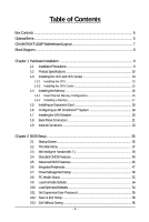
GA-MA790XT-UD4P Motherboard Layout 7 Block Diagram ...8 Chapter 1 Hardware Installation 9 1-1 Installation Precautions 9 1-2 Product Specifications 10 1-3 Installing the CPU and CPU Cooler 13 1-3-1 Installing the CPU 13 1-3-2 Installing the CPU Cooler 15 1-4 Installing the Memory BIOS - Gigabyte GA-MA790XT-UD4P | Manual - Page 5
Chipset Drivers 57 3-2 Application Software 58 3-3 Technical Manuals 58 3-4 Contact ...59 3-5 System ...59 3-6 Download Center 60 Chapter 4 Unique Features 61 4-1 Xpress Recovery2 61 4-2 BIOS Update Utilities 64 4-2-1 Updating the BIOS with the Q-Flash Utility 64 4-2-2 Updating the BIOS with - Gigabyte GA-MA790XT-UD4P | Manual - Page 6
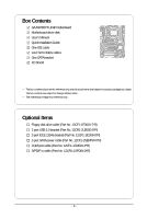
Box Contents GA-MA790XT-UD4P motherboard Motherboard driver disk User's Manual Quick Installation Guide One IDE cable Four SATA 3Gb/s cables One SATA bracket I/O Shield • The box contents above are for reference only and the actual items shall depend - Gigabyte GA-MA790XT-UD4P | Manual - Page 7
GA-MA790XT-UD4P Motherboard Layout KB_MS CPU_FAN ATX RCA_SPDIF ATX_12V_2X4 R_USB Socket AM3 USB_1394_1 USB_1394 PWR_FAN USB IT8720 LAN AUDIO F_AUDIO PCIEX1_1 RTL8111C/D(L) PCIEX16_1 PCIEX1_2 CD_IN CODEC PCIEX1_3 SPDIF_IN SPDIF_OUT PCIEX8_1 PCI1 PCI2 COM FDD CI IDE AMD 790X - Gigabyte GA-MA790XT-UD4P | Manual - Page 8
or AM3 CPU CPU CLK+/-(200 MHz) DDR3 1666(O.C.)/1333/1066 MHz Hyper Transport 3.0 Dual Channel Memory Switch PCI Express Bus PCI Express Bus x1 x1 x1 x1 PCIe CLK (100 MHz) 3 PCI Express x1 RJ45 RTL8111C/D(L) LAN 2 SATA 3Gb/s PCI Bus GIGABYTE SATA2 TSB43AB23 AMD 790X AMD SB750 Dual BIOS - Gigabyte GA-MA790XT-UD4P | Manual - Page 9
's manual and follow these procedures: • Prior to installation, do not remove or break motherboard S/N wrist strap when handling electronic components such as a motherboard, CPU or memory. If you do not have an ESD wrist steps or have a problem related to the use of the product, please consult - Gigabyte GA-MA790XT-UD4P | Manual - Page 10
USB Support for Socket AM3 processors: AMD PhenomTM II X4 processor/AMD PhenomTM II X3 processor (Go to GIGABYTE's website for the latest CPU support list.) 5200 MT/s North Bridge: AMD 790X South Bridge: AMD SB750 4 x 1.5V DDR3 DIMM sockets supporting up to 16 GB of system memory (Note - Gigabyte GA-MA790XT-UD4P | Manual - Page 11
System voltage detection CPU/System temperature detection CPU/System/Power fan speed detection CPU overheating warning CPU/System/Power fan fail warning CPU/System fan speed control (Note 3) BIOS 2 x 8 Mbit flash Use of licensed AWARD BIOS Support for DualBIOSTM PnP - Gigabyte GA-MA790XT-UD4P | Manual - Page 12
Express graphics card, the PCIEX16_1 slot will operate at up to x8 mode. (Note 3) Whether the CPU/system fan speed control function is supported will depend on the CPU/ system cooler you install. (Note 4) Available functions in EasyTune may differ by motherboard model. GA-MA790XT-UD4P Motherboard - Gigabyte GA-MA790XT-UD4P | Manual - Page 13
before you begin to install the CPU: • Make sure that the motherboard supports the CPU. (Go to GIGABYTE's website for the latest CPU support list.) • Always turn off the computer and unplug the power cord from the power outlet before installing the CPU to prevent hardware damage. • Locate the - Gigabyte GA-MA790XT-UD4P | Manual - Page 14
its socket, place one finger down on the middle of the CPU, lowering the locking lever and latching it into the fully locked position. Do not force the CPU into the CPU socket. The CPU cannot fit in if oriented incorrectly. Adjust the CPU orientation if this occurs. GA-MA790XT-UD4P Motherboard - Gigabyte GA-MA790XT-UD4P | Manual - Page 15
lock into place. (Refer to your CPU cooler installation manual for instructions on installing the cooler.) Step 5: Finally, attach the power connector of the CPU cooler to the CPU fan header (CPU_FAN) on the motherboard. Use extreme care when removing the CPU cooler because the thermal grease/tape - Gigabyte GA-MA790XT-UD4P | Manual - Page 16
only one DDR3 memory module is installed. 2. When enabling Dual Channel mode with two or four memory modules, it is recommended that memory of the same capacity, brand, speed, and chips be used and installed in the same colored DDR3 sockets for optimum performance. GA-MA790XT-UD4P Motherboard - 16 - Gigabyte GA-MA790XT-UD4P | Manual - Page 17
. Be sure to install DDR3 DIMMs on this motherboard. Notch DDR3 DIMM A DDR3 memory module has a notch, so it can only fit in one direction. Follow the steps below to correctly install your memory modules in the memory sockets. Step 1: Note the orientation of the memory module. Spread the retaining - Gigabyte GA-MA790XT-UD4P | Manual - Page 18
Make sure the motherboard supports the expansion card. Carefully read the manual that came with your expansion card. • Always turn off the computer and unplug the power cord from the power outlet before installing an expansion card to prevent hardware damage. PCI Express x1 Slot PCI Express x16 Slot - Gigabyte GA-MA790XT-UD4P | Manual - Page 19
Configuration A. System Requirements - Windows Vista or Windows XP operating system - A CrossFireX-supported motherboard with two PCI Express x16 slots and correct driver - Two CrossFireX-ready graphics cards of identical brand and chip and correct driver - Two CrossFire bridge connectors (Note - Gigabyte GA-MA790XT-UD4P | Manual - Page 20
panel with a screw. Step 2: Connect the SATA cable from the bracket to the SATA port on your motherboard. Step 3: Step 4: Connect the power Plug one end of the cable from the bracket SATA signal cable sure to turn off the power of the external enclosure. GA-MA790XT-UD4P Motherboard - 20 - - Gigabyte GA-MA790XT-UD4P | Manual - Page 21
audio in connector. USB Port The USB port supports the USB 2.0/1.1 specification. Use this port for states of the LAN port LEDs. Connection/ Speed LED Activity LED LAN Port Connection/Speed LED from your device and then remove it from the motherboard. • When removing the cable, pull it straight - Gigabyte GA-MA790XT-UD4P | Manual - Page 22
perform different functions via the audio software. Only microphones still MUST be connected to the default Mic in jack ( ). Refer to the instructions on setting up a 2/4/5.1/ 7.1-channel audio configuration in Chapter 5, "Configuring 2/4/5.1/7.1-Channel Audio." GA-MA790XT-UD4P Motherboard - 22 - - Gigabyte GA-MA790XT-UD4P | Manual - Page 23
3 1 5 2 7 12 13 21 8 15 14 20 9 18 10 19 6 17 16 4 11 4 1) ATX_12V_2X4 2) ATX 3) CPU_FAN 4) SYS_FAN1/SYS_FAN2 5) PWR_FAN 6) FDD 7) IDE 8) SATA2_0 / 1 / 2 / 3 / 4 / 5 9) GSATA2_0/GSATA_1 has been securely attached to the connector on the motherboard. - 23 - Hardware Installation - Gigabyte GA-MA790XT-UD4P | Manual - Page 24
the power connector in the correct orientation. The 12V power connector mainly supplies power to the CPU. If the 12V power connector is not connected, the computer will not start. • To GND GND -5V +5V +5V +5V (Only for 2x12-pin ATX) GND (Only for 2x12-pin ATX) GA-MA790XT-UD4P Motherboard - 24 - - Gigabyte GA-MA790XT-UD4P | Manual - Page 25
fan cable, be sure to connect it in the correct orientation (the black connector wire is the ground wire). The motherboard supports CPU fan speed control, which requires the use of a CPU fan with fan speed control design. For optimum heat dissipation, it is recommended that a system fan be installed - Gigabyte GA-MA790XT-UD4P | Manual - Page 26
number. • A RAID 5 configuration requires at least three hard drives. (The total number of hard drives does not have to be an even number.) • A RAID 10 configuration requires at least four hard drives and the total number of hard drives must be an even number. GA-MA790XT-UD4P Motherboard - 26 - - Gigabyte GA-MA790XT-UD4P | Manual - Page 27
with SATA 1.5Gb/s standard. Each SATA connector supports a single SATA device. The GIGABYTE SATA2 controller supports RAID 0, RAID 1, and JBOD. Refer to Chapter 5, "Configuring SATA Hard Drive(s)," for instructions on configuring a RAID array. Pin No. Definition 1 GND 2 TXP 3 TXN - Gigabyte GA-MA790XT-UD4P | Manual - Page 28
problem is detected at system startup. If a problem is detected, the BIOS may issue beeps in different patterns to indicate the problem. Refer to Chapter 5, "Troubleshooting to restart the computer if the computer freezes and fails to perform a normal restart. GA-MA790XT-UD4P Motherboard - 28 - - Gigabyte GA-MA790XT-UD4P | Manual - Page 29
the pin assignments of the motherboard header. Incorrect connection between the module connector and the motherboard header will make the device front panel audio header supports HD audio by default. If your chassis provides an AC'97 front panel audio module, refer to the instructions on how to - Gigabyte GA-MA790XT-UD4P | Manual - Page 30
This header supports digital S/PDIF out and connects a S/PDIF digital audio cable (provided by expansion cards) for digital audio output from your motherboard to certain , carefully read the manual for your expansion card. Pin No. Definition 1 SPDIFO 1 2 GND GA-MA790XT-UD4P Motherboard - 30 - - Gigabyte GA-MA790XT-UD4P | Manual - Page 31
16) F_USB1/F_USB2 (USB Headers) The headers conform to USB 2.0/1.1 specification. Each USB header can provide two USB ports via an optional USB bracket. For purchasing the optional USB bracket, please contact the local dealer. 9 1 10 2 Pin No. 1 2 3 4 5 6 7 8 9 10 Definition Power (5V) Power ( - Gigabyte GA-MA790XT-UD4P | Manual - Page 32
No Pin 19) CI (Chassis Intrusion Header) This motherboard provides a chassis detection feature that detects if the chassis cover has been removed. This function requires a chassis with chassis intrusion detection design. Pin No. Definition 1 Signal 1 2 GND GA-MA790XT-UD4P Motherboard - 32 - - Gigabyte GA-MA790XT-UD4P | Manual - Page 33
Failure to do so may cause damage to the motherboard. • After system restart, go to BIOS Setup to load factory defaults (select Load Optimized Defaults) or manually configure the BIOS settings (refer to Chapter 2, "BIOS Setup," for BIOS configurations). 21) BATTERY The battery provides power to keep - Gigabyte GA-MA790XT-UD4P | Manual - Page 34
GA-MA790XT-UD4P Motherboard - 34 - - Gigabyte GA-MA790XT-UD4P | Manual - Page 35
upgrade or back up BIOS without entering the operating system. • @BIOS is a Windows-based utility that searches and downloads the latest version of BIOS from the Internet and updates the BIOS. For instructions on using the Q-Flash and @BIOS utilities, refer to Chapter 4, "BIOS Update Utilities - Gigabyte GA-MA790XT-UD4P | Manual - Page 36
boots. A. The LOGO Screen (Default) B. The POST Screen Award Modular BIOS v6.00PG, An Energy Star Ally Copyright (C) 1984-2009, Award Software, Inc. Motherboard Model BIOS Version GA-MA790XT-UD4P F4e . . . . : BIOS Setup : XpressRecovery2 : Boot Menu : Qflash 04/30/2009 - Gigabyte GA-MA790XT-UD4P | Manual - Page 37
& Exit Setup Exit Without Saving ESC: Quit F8: Q-Flash Select Item F10: Save & Exit Setup F11: Save CMOS to BIOS F12: Load CMOS from BIOS Time, Date, Hard Disk Type... BIOS Setup Program Function Keys Move the selection bar to select an item Execute command or enter the submenu - Gigabyte GA-MA790XT-UD4P | Manual - Page 38
and exit BIOS Setup. (Pressing can also carry out this task.) Exit Without Saving Abandon all changes and the previous settings remain in effect. Pressing to the confirmation message will exit BIOS Setup. (Pressing can also carry out this task.) GA-MA790XT-UD4P Motherboard - 38 - Gigabyte GA-MA790XT-UD4P | Manual - Page 39
your overall system configurations. Incorrectly doing overclock/overvoltage may result in damage to CPU, chipset, or memory and reduce the useful life of , select Save & Exit Setup in the BIOS Main Menu and then press Y. A message which says "BIOS Is Updating EC Firmware!!! Don't Turn Off Or Reset - Gigabyte GA-MA790XT-UD4P | Manual - Page 40
Frequency toX1~X10 (200 MHz~2000 MHz). Set Memory Clock Determines whether to manually set the memory clock. Auto lets BIOS automatically set the memory clock as required. Manual allows the memory clock control item below to be configurable. (Default: Auto) GA-MA790XT-UD4P Motherboard - 40 - - Gigabyte GA-MA790XT-UD4P | Manual - Page 41
CPU Host Clock Control x CPU Frequency (MHz) Set Memory Clock x Memory Clock DCTs Mode DDR3 memory control mode. Ganged Sets memory control mode to single dual-channel. Unganged Sets memory control mode to two single-channel.(Default) DDR3 Timing Items Manual allows all DDR3 BIOS Setup - Gigabyte GA-MA790XT-UD4P | Manual - Page 42
required. The adjustable range is dependent on the CPU being installed. (Default: Normal) Note: Increasing CPU voltage may result in damage to your CPU or reduce the useful life of the CPU. Normal CPU Vcore Displays the normal operating voltage of your CPU. GA-MA790XT-UD4P Motherboard - 42 - - Gigabyte GA-MA790XT-UD4P | Manual - Page 43
[None] Drive A Floppy 3 Mode Support [1.44M, 3.5"] [Disabled] Halt On [All, But Keyboard] Base Memory Extended Memory Move Enter: Select F5: Previous Values devices by using one of the two methods below: • Auto Lets BIOS automatically detect IDE/SATA devices during the POST. (Default) • - Gigabyte GA-MA790XT-UD4P | Manual - Page 44
manually 3 Mode Support Allows you Memory These fields are read-only and are determined by the BIOS POST. Base Memory Also called conventional memory. Typically, 640 KB will be reserved for the MS-DOS operating system. Extended Memory The amount of extended memory. GA-MA790XT-UD4P Motherboard - Gigabyte GA-MA790XT-UD4P | Manual - Page 45
AMD K8 Cool&Quiet control Auto Lets the AMD Cool'n'Quiet driver dynamically adjust the CPU >) to move it up or down on the list. Press to exit this menu when LAN, Disabled. Password Check Specifies whether a password is required every time the system boots, or only when you enter BIOS - Gigabyte GA-MA790XT-UD4P | Manual - Page 46
or PCI Express graphics card. PCI Slot Sets the PCI graphics card as the first display. (Default) PEG Sets the PCI Express graphics card on the PCIEX16_1 slot as the first display. PEG1 Sets the PCI Express graphics card on the PCIEX8_1 slot as the first display. GA-MA790XT-UD4P Motherboard - Gigabyte GA-MA790XT-UD4P | Manual - Page 47
Port4/5 Type Onboard Audio Function Onboard GSATA-II Ctrl Onboard GSATA-II Ctrl Mode Onboard LAN Function Onboard LAN Boot ROM SMART LAN Onboard 1394 Function OnChip USB Controller USB EHCI Controller USB Keyboard Support USB Mouse Support Legacy USB storage detect Onboard Serial Port 1 [Enabled - Gigabyte GA-MA790XT-UD4P | Manual - Page 48
to the following information for diagnosing your LAN cable: When No LAN Cable Is Attached... If no LAN cable is attached to the motherboard, the Status fields of all four pairs of wires will show Open and the Length fields show 0m, as shown in the figure above. GA-MA790XT-UD4P Motherboard - 48 - - Gigabyte GA-MA790XT-UD4P | Manual - Page 49
of 10/100/1000 Mbps in Windows mode or when the LAN Boot ROM is activated. When a Cable Problem Occurs... If a cable problem occurs on a specified pair of Default: Enabled) USB Keyboard Support Allows USB keyboard to be used in MS-DOS. (Default: Enabled) USB Mouse Support Allows USB mouse to be - Gigabyte GA-MA790XT-UD4P | Manual - Page 50
at any time. Enables the system to enter the ACPI S3 (Suspend to RAM) sleep state (default). In S3 sleep state, the system appears to be off a modem that supports wake-up function. (Default: Disabled) (Note) Supported on Windows® Vista® operating system only. GA-MA790XT-UD4P Motherboard - 50 - - Gigabyte GA-MA790XT-UD4P | Manual - Page 51
PCI or PCIe device. Note: To use this function, you need an ATX power supply providing at least 1A on the +5VSB lead. (Default: Enabled) HPET Support (Note) Enables or disables High Precision Event Timer (HPET) for Windows Memory Supported on Windows® Vista® operating system only. - 51 - BIOS Setup - Gigabyte GA-MA790XT-UD4P | Manual - Page 52
the motherboard CI header. If the system chassis cover is removed, this field will show "Yes", otherwise it will show "No". To clear the chassis intrusion status record, set Reset Case Open Status to Enabled, save the settings to CMOS, and then restart your system. GA-MA790XT-UD4P Motherboard - 52 - Gigabyte GA-MA790XT-UD4P | Manual - Page 53
FAN Control is set to Enabled. Auto Voltage PWM Lets BIOS autodetect the type of CPU fan installed and sets the optimal CPU fan control mode. (Default) Sets Voltage mode for a 3-pin CPU fan. Sets PWM mode for a 4-pin CPU fan. System Smart FAN Control Enables or disables the system fan speed - Gigabyte GA-MA790XT-UD4P | Manual - Page 54
BIOS Press on this item and then press the key to load the optimal BIOS default settings. The BIOS defaults settings helps the system to operate in optimum state. Always load the Optimized defaults after updating the BIOS or after clearing the CMOS values. GA-MA790XT-UD4P Motherboard - Gigabyte GA-MA790XT-UD4P | Manual - Page 55
changes. When the Password Check item is set to System, you must enter the supervisor password (or user password) at system startup and when entering BIOS Setup. User Password When the Password Check item is set to System, you must enter the supervisor password (or user password) at system startup - Gigabyte GA-MA790XT-UD4P | Manual - Page 56
Abandon all Data F11: Save CMOS to BIOS F12: Load CMOS from BIOS Press on this item and press the key. This exits the BIOS Setup without saving the changes made in BIOS Setup to the CMOS. Press or to return to the BIOS Setup Main Menu. GA-MA790XT-UD4P Motherboard - 56 - - Gigabyte GA-MA790XT-UD4P | Manual - Page 57
other drivers. • After the drivers are installed, follow the onscreen instructions to restart your system. You can install other applications included in the motherboard driver disk. • For USB 2.0 driver support under the Windows XP operating system, please install the Windows XP Service Pack - Gigabyte GA-MA790XT-UD4P | Manual - Page 58
that GIGABYTE develops and some free software. You can click the Install button on the right of an item to install it. 3-3 Technical Manuals This page provides GIGABYTE's application guides, content descriptions for this driver disk, and the motherboard manuals. GA-MA790XT-UD4P Motherboard - 58 - - Gigabyte GA-MA790XT-UD4P | Manual - Page 59
3-4 Contact For the detailed contact information of the GIGABYTE Taiwan headquarter or worldwide branch offices, click the URL on this page to link to the GIGABYTE Website. 3-5 System This page provides the basic system information. - 59 - Drivers Installation - Gigabyte GA-MA790XT-UD4P | Manual - Page 60
3-6 Download Center To update the BIOS, drivers, or applications, click the Download Center button to link to the GIGABYTE Web site. The latest version of the BIOS, drivers, or applications will be displayed. GA-MA790XT-UD4P Motherboard - 60 - - Gigabyte GA-MA790XT-UD4P | Manual - Page 61
be restored using Xpress Recovery2. • USB hard drives are not supported. • Hard drives in RAID/AHCI mode are not supported. Installation and Configuration Turn on your system to boot from the Windows Vista setup disk. A. Installing Windows Vista and Partitioning the Hard Drive Step 1: Click Drive - Gigabyte GA-MA790XT-UD4P | Manual - Page 62
Xpress Recovery2 cannot save the backup file. B. Accessing Xpress Recovery2 1. Boot from the motherboard driver disk to access Xpress Recovery2 for the first time. When you see the following message When finished, go to Disk Management to check disk allocation. GA-MA790XT-UD4P Motherboard - 62 - - Gigabyte GA-MA790XT-UD4P | Manual - Page 63
D. Using the Restore Function in Xpress Recovery2 Select RESTORE to restore the backup to your hard drive in case the system breaks down. The RESTORE option will not be present if no backup is created before. E. Removing the Backup Step 1: If you wish to remove the backup file, select REMOVE. F. - Gigabyte GA-MA790XT-UD4P | Manual - Page 64
GA-MA790XT-UD4P F4e . . . . : BIOS Setup : XpressRecovery2 : Boot Menu : Qflash 04/30/2009-RD780-SB750-7A66AG03C-00 Because BIOS flashing is potentially risky, please do it with caution. Inadequate BIOS flashing may result in system malfunction. GA-MA790XT-UD4P Motherboard - 64 - Gigabyte GA-MA790XT-UD4P | Manual - Page 65
arrow key to select Update BIOS from Drive and press . • The Save Main BIOS to Drive option allows you to save the current BIOS file. • Q-Flash only supports USB flash drive or hard drives using FAT32/16/12 file system. • If the BIOS update file is saved to a hard drive in RAID/AHCI mode or - Gigabyte GA-MA790XT-UD4P | Manual - Page 66
Setup Load Optimized Defaults F11: Save CMOS to BIOS F12: Load CMOS from BIOS Press to load BIOS defaults Step 6: Select Save & Exit Setup and then press to save settings to CMOS and exit BIOS Setup. The procedure is complete after the system restarts. GA-MA790XT-UD4P Motherboard - 66 - - Gigabyte GA-MA790XT-UD4P | Manual - Page 67
to your location and then download the BIOS file that matches your motherboard model. Follow the on- screen instructions to complete. If the BIOS update file for your motherboard is not present on the @BIOS server site, please manually download the BIOS update file from GIGABYTE's website and - Gigabyte GA-MA790XT-UD4P | Manual - Page 68
hardware components such as CPU, chipset, and memory and reduce the useful life of these components. Before you do the overclock/overvoltage, make sure that you fully know each function of EasyTune 6, or system instability or other unexpected results may occur. GA-MA790XT-UD4P Motherboard - 68 - - Gigabyte GA-MA790XT-UD4P | Manual - Page 69
will continue to run in taskbar) 14 INFO/Help 15 Live Utility Update (Check for the latest utility version) • The above data is for reference only. Actual performance may vary depending on motherboard model. • CPU Power and Power Scores are for reference only. Actual results may vary - Gigabyte GA-MA790XT-UD4P | Manual - Page 70
continue to run in taskbar) 13 INFO/Help 14 Live Utility Update (Check for the latest utility version) C. Stealth Mode In the application. (Note 1) Maximize system power saving with Dynamic CPU Frequency Function; system performance may be affected. (Note 2) GA-MA790XT-UD4P Motherboard - 70 - - Gigabyte GA-MA790XT-UD4P | Manual - Page 71
LAN connection settings and Q-Share, you are able to share your data with computers on the same network, making full use of Internet resources. Directions for using Q-Share After installing Q-Share from the motherboard driver folder to be shared (Note) Updates Q-Share online Displays the current Q- - Gigabyte GA-MA790XT-UD4P | Manual - Page 72
and over 300 MB of available space. • Each storage volume can accommodate 64 shadow copies. When this limit is reached, the oldest shadow copy will be deleted and unable to be restored. Shadow copies are read-only so you cannot edit the contents of a shadow copy. GA-MA790XT-UD4P Motherboard - 72 - - Gigabyte GA-MA790XT-UD4P | Manual - Page 73
identical model and capacity). If you do not want to create RAID, you may prepare only one hard drive. • An empty formatted floppy disk. • Windows Vista/XP setup disk. • Motherboard driver disk. 5-1-1 Configuring AMD SB750 SATA Controllers A. Installing SATA hard drive(s) in your computer Attach - Gigabyte GA-MA790XT-UD4P | Manual - Page 74
Step 2: Save changes and exit BIOS Setup. The BIOS Setup menus described in this section may differ from the exact settings for your motherboard. The actual BIOS Setup menu options you will see shall depend on the motherboard you have and the BIOS version. GA-MA790XT-UD4P Motherboard - 74 - - Gigabyte GA-MA790XT-UD4P | Manual - Page 75
This is the first option screen when you enter the BIOS RAID Setup utility. (Figure 3). To view the disk drives assigned to arrays, press to enter the View Drive Assignments window. To create an array, press to enter the Define LD window. To delete an array, press to enter the Delete LD - Gigabyte GA-MA790XT-UD4P | Manual - Page 76
window (Figure 4). The Define LD selection from the Main Menu allows users to begin the process of manually defining the drive elements and RAID levels for one or multiple disk arrays attached to the AMD Space] Change [Ctrl-Y] Save [PgUp/Dn] Page Change Figure 5 GA-MA790XT-UD4P Motherboard - 76 - - Gigabyte GA-MA790XT-UD4P | Manual - Page 77
RAID 0 as an example. 1. Under the RAID Mode section, press the key to select RAID 0. 2. Set the Stripe Block size. 64 information. The window below will RAID BIOS utility. View Drive Assignments The View Drive Assignments option in the Main Menu displays whether drives attached to the AMD - Gigabyte GA-MA790XT-UD4P | Manual - Page 78
2008 Advanced Micro Devices, Inc. LD No [ View LD Definition Menu ] RAID Mode Total Drv Capacity (GB) Status LD 1 RAID 0 2 157.99 Functional Stripe Block: 64KB Cache Mode: WriteThru [ Drives in the disk! or press any other key to abort... Figure 9 GA-MA790XT-UD4P Motherboard - 78 - - Gigabyte GA-MA790XT-UD4P | Manual - Page 79
Onboard GSATA-II Ctrl Mode Onboard LAN Function Onboard LAN Boot ROM SMART LAN Onboard 1394 Function OnChip USB Controller USB EHCI Controller USB Keyboard Support USB Mouse Support Legacy USB storage detect Onboard Serial Port 1 [Enabled] [Enabled] [Native IDE] [IDE] [Enabled] [Enabled] [RAID - Gigabyte GA-MA790XT-UD4P | Manual - Page 80
[ RAID Disk Drive List ] [TAB]-Switch Window []-Select ITEM [ENTER]-Action Figure 3 [ESC]-Exit Note: In the main screen, you can select a hard drive in the Hard Disk Drive List block and press to see detailed information about the selected hard drive. GA-MA790XT-UD4P Motherboard - Gigabyte GA-MA790XT-UD4P | Manual - Page 81
or JBOD (Figure 5). Then press to move onto the next step. GIGABYTE Technology Corp. PCIE-to-SATAII/IDE RAID Controller BIOS v1.06.59 [ Create New RAID ] [ Hard Disk Drive List ] Name: GRAID Level: 0-Stripe Disks: Select Disk Block: 128 KB Size: 240 GB Model Name HDD0: ST3120026AS HDD1 - Gigabyte GA-MA790XT-UD4P | Manual - Page 82
RAID Non-RAID Confirm Creation [ RAID Disk Drive List ] Create RAID [onHethlpe ]select HDD(Y/N)?Y CONFIRM RAID CREATION ALL DATA ON THE SELECTED HARD DISK WILL BE LOST WHEN EXIT WITH SAVING []-Switch Unit [DEL,BS]-Delete Number Figure 7 [ENTER]-Next [ESC]-Abort GA-MA790XT-UD4P Motherboard - Gigabyte GA-MA790XT-UD4P | Manual - Page 83
and press . A small window displaying the array information will appear in the center of the screen (Figure 9). GIGABYTE Technology Corp. PCIE-to-SATAII/IDE RAID Controller BIOS v1.06.59 [ Main Menu ] [ Hard Disk Drive List ] Create RAID Disk Drive Delete RAID Disk Drive Revert HDD to Non - Gigabyte GA-MA790XT-UD4P | Manual - Page 84
Inside RAID Inside [ RAID Disk Drive List ] Model Name RDD0: GRAID ALL DATA ON THE RAID WILL LOST!! ARE YOU SURE TO DELETE (Y/N)? N RAID Level Capacity Status 0-Stripe 240 GB Normal Members(HDDx) 01 []-Select RAID [SPACE]-Mark Delete [DEL]-Confirm Figure 11 GA-MA790XT-UD4P Motherboard - Gigabyte GA-MA790XT-UD4P | Manual - Page 85
in Figure 4, • For the AMD SB750, select 3) SB700/710/750 SATA Driver for XP for operating system. • For the GIGABYTE SATA2, select 1) GIGABYTE GSATA driver for 32bit system for Windows 32-bit operating system or 2) GIGABYTE GSATA driver for 64bit system for Windows 64-bit. Your system will then - Gigabyte GA-MA790XT-UD4P | Manual - Page 86
by an adapter manufacturer. Select the SCSI Adapter you want from the following list, or press ESC to return to the previous screen. AMD AHCI Compatible RAID Controller-x86 platform AMD AHCI Compatible RAID Controller-x64 platform ENTER=Select F3=Exit GA-MA790XT-UD4P Motherboard Figure 2 - 86 - - Gigabyte GA-MA790XT-UD4P | Manual - Page 87
for use with Windows, using a device support disk provided by an adapter manufacturer. Select the SCSI Adapter you want from the following list, or press ESC to return to the previous screen. (Windows XP/2003) RAID/AHCI Driver for GIGABYTE GBB36X Controller (Windows 2000) RAID Driver for GIGABYTE - Gigabyte GA-MA790XT-UD4P | Manual - Page 88
the following directory: \BootDrv\SB750V\LH For Windows Vista 64-bit, browse to the LH64A folder. Method B: Insert the USB flash drive containing the driver files and browse to the LH (for Windows Vista 32-bit) or LH64A (for Windows Vista 64-bit) folder. GA-MA790XT-UD4P Motherboard Figure 5 - 88 - - Gigabyte GA-MA790XT-UD4P | Manual - Page 89
Step 3: When a screen as shown in Figure 6 appears, select AMD AHCI Compatible RAID Controller and press Next. Figure 6 Step 4: After the driver is loaded, the RAID drive will appear. Select the RAID drive and then press Next to continue the OS installation (Figure 7). Figure 7 The install menus - Gigabyte GA-MA790XT-UD4P | Manual - Page 90
following directory: \BootDrv\GSATA\Floppy32 For Windows Vista 64-bit, browse to the 64Bit folder. Method B: Insert the USB flash drive containing the driver files and browse to Floppy32 (for Windows Vista 32bit) or Floppy64 (for Windows Vista 64-bit). GA-MA790XT-UD4P Motherboard Figure 9 - 90 - - Gigabyte GA-MA790XT-UD4P | Manual - Page 91
Step 3: When a screen as shown in Figure 10 appears, select GIGABYTE GBB36X Controller and press Next. Figure 10 Step 4: After the driver is loaded, select the RAID/AHCI drive(s) where you want to install the operating system and then press Next to continue the OS installation (Figure 11). Figure - Gigabyte GA-MA790XT-UD4P | Manual - Page 92
sure the chipset drivers and ATi SB700/750 RAID Utility have been installed from the motherboard driver disk. Then launch the AMD RAIDXpert from All Programs select Pause/Resume/ Abort/Restart during the rebuilding process. GA-MA790XT-UD4P Motherboard Step 5: When done, the array's status on the - Gigabyte GA-MA790XT-UD4P | Manual - Page 93
HDD0: ST3120026AS HDD1: ST3120026AS Capacity Type/Status 120 GB RAID Inside 120 GB Non-RAID [ RAID Disk Drive List ] Model Name RDD0: GRAID RAID Level 1-Mirror Capacity Status Members(HDDx) 120 GB Degraded 0? [TAB]-Switch Window []-Select ITEM [ENTER]-Action [ESC]-Exit Step 2: The - Gigabyte GA-MA790XT-UD4P | Manual - Page 94
appears, click Next. Step 3: Select a drive to rebuild the array and click Next. Step 4: Click Finish to start the RAID rebuilding process. Step 6: When finished, restart your system. Step 5: The rebuilding progress is displayed at the bottom of the screen. GA-MA790XT-UD4P Motherboard - 94 - - Gigabyte GA-MA790XT-UD4P | Manual - Page 95
2/4/5.1/7.1-Channel Audio The motherboard provides six audio jacks on the back panel which support 2/4/5.1/7.1-channel audio. The Configuring Speakers: (The following instructions use Windows Vista as the example operating system.) Step 1: After installing the audio driver, the HD Audio Manager - Gigabyte GA-MA790XT-UD4P | Manual - Page 96
OK. Step 3: On the Speakers screen, click the Speaker Configuration tab. In the Speaker Configuration list, select Stereo, Quadraphonic, 5.1 Speaker, or 7.1 Speaker according to the type of speaker configuration plugged in check box. Click OK to complete. GA-MA790XT-UD4P Motherboard - 96 - - Gigabyte GA-MA790XT-UD4P | Manual - Page 97
S/PDIF In 1. Installing the S/PDIF In Cable: Step 1: First, attach the connector at the end of the cable to the SPDIF_I header on your motherboard. Step 2: Secure the metal bracket to the chassis back panel with a screw. 2. Configuring S/PDIF In: On the Digital Input screen, click the Default - Gigabyte GA-MA790XT-UD4P | Manual - Page 98
the S/PDIF digital audio signals. 2. Configuring S/PDIF Out: On the Digital Output screen, click the Default Format tab and then select the sample rate and bit depth. Click OK to complete. GA-MA790XT-UD4P Motherboard - 98 - - Gigabyte GA-MA790XT-UD4P | Manual - Page 99
will be transformed into multi-channel audio, creating a virtual surround sound environment . (Note) Install the Dolby GUI Software driver from the motherboard driver disk. Click the Start icon to All Programs, Dolby Control Center to access the utility. (The following illustration demonstrates - Gigabyte GA-MA790XT-UD4P | Manual - Page 100
5-2-4 Configuring Microphone Recording Step 1: After installing the audio driver, the HD Audio Manager icon will appear in the notification area. Doubleclick the icon input default device to microphone, right-click on Microphone and select Set Default Device. GA-MA790XT-UD4P Motherboard - 100 - - Gigabyte GA-MA790XT-UD4P | Manual - Page 101
Step 4: To raise the recording and playback volume for the microphone, click the Microphone Boost icon on the right of the Recording Volume slider and set the Microphone Boost level. Step 5: After completing the settings above, click Start, point to All Programs, point to Accessories, and then click - Gigabyte GA-MA790XT-UD4P | Manual - Page 102
. Be sure to save the recorded audio file upon completion. B. Playing the Recorded Sound: You can play your recording in a digital media player program that supports your audio file format. GA-MA790XT-UD4P Motherboard - 102 - - Gigabyte GA-MA790XT-UD4P | Manual - Page 103
5-3 Troubleshooting 5-3-1 Frequently Asked Questions To read more FAQs for your motherboard, please go to the Support\Motherboard\FAQ page on GIGABYTE's website. Q:In the BIOS Setup program, why are some BIOS options missing? A: Some advanced options are hidden in the BIOS Setup program. Press < - Gigabyte GA-MA790XT-UD4P | Manual - Page 104
Connect the ATX main power cable and the 12V power cable. Turn on the power to start the computer. Make sure the graphics card is securely seated in the expansion slot and power connectors are firmly attached. A The problem is verified and solved. (Continued...) GA-MA790XT-UD4P Motherboard - 104 - Gigabyte GA-MA790XT-UD4P | Manual - Page 105
CPU socket might fail. The problem is verified and solved. No The graphics card, expansion slot, or monitor might fail. The problem is verified and solved. Check if the keyboard is working properly. Yes Press to enter BIOS Setup. Select "Load Fail-Safe Defaults" (or "Load Optimized - Gigabyte GA-MA790XT-UD4P | Manual - Page 106
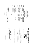
please contact your local government office, your household waste disposal service or where you purchased the product for details of environmentally the Customer Care number listed in your product's user's manual and we will be glad to help you with your effort. GA-MA790XT-UD4P Motherboard - 106 - - Gigabyte GA-MA790XT-UD4P | Manual - Page 107
Finally, we suggest that you practice other environmentally friendly actions by understanding and using the energy-saving features of this product (where applicable), recycling the inner and outer packaging (including shipping containers) this product was delivered in, and by disposing of or - Gigabyte GA-MA790XT-UD4P | Manual - Page 108
GA-MA790XT-UD4P Motherboard - 108 - - Gigabyte GA-MA790XT-UD4P | Manual - Page 109
- 109 - Appendix - Gigabyte GA-MA790XT-UD4P | Manual - Page 110
GA-MA790XT-UD4P Motherboard - 110 - - Gigabyte GA-MA790XT-UD4P | Manual - Page 111
CO., LTD. Address: No.6, Bau Chiang Road, Hsin-Tien, Taipei 231, Taiwan TEL: +886-2-8912-4000 FAX: +886-2-8912-4003 Tech. and Non-Tech. Support (Sales/Marketing) : http://ggts.gigabyte.com.tw WEB address (English): http://www.gigabyte.com.tw WEB address (Chinese): http://www.gigabyte.tw G.B.T. INC - Gigabyte GA-MA790XT-UD4P | Manual - Page 112
in the language list on the top right corner of the website. GIGABYTE Global Service System To submit a technical or non-technical (Sales/ Marketing) question, please link to : http://ggts.gigabyte.com.tw Then select your language to enter the system. GA-MA790XT-UD4P Motherboard - 112 -
-
 1
1 -
 2
2 -
 3
3 -
 4
4 -
 5
5 -
 6
6 -
 7
7 -
8
-
9
-
10
-
11
-
12
-
13
-
14
-
15
-
16
-
17
-
18
-
19
-
20
-
21
-
22
-
23
-
24
-
25
-
26
-
27
-
28
-
29
-
30
-
31
-
32
-
33
-
34
-
35
-
36
-
37
-
38
-
39
-
40
-
41
-
42
-
43
-
44
-
45
-
46
-
47
-
48
-
49
-
50
-
51
-
52
-
53
-
54
-
55
-
56
-
57
-
58
-
59
-
60
-
61
-
62
-
63
-
64
-
65
-
66
-
67
-
68
-
69
-
70
-
71
-
72
-
73
-
74
-
75
-
76
-
77
-
78
-
79
-
80
-
81
-
82
-
83
-
84
-
85
-
86
-
87
-
88
-
89
-
90
-
91
-
92
-
93
-
94
-
95
-
96
-
97
-
98
-
99
-
100
-
101
-
102
-
103
-
104
-
105
-
106
-
107
-
108
-
109
-
110
-
111
-
112
 |
 |

GA-MA790XT-UD4P
AM3 socket motherboard for
AMD Phenom
TM
II X4 processor/AMD Phenom
TM
II X3 processor
User's Manual
Rev. 1004
12ME-MA79T4P-1004R