Gigabyte GA-MF3 Manual
Gigabyte GA-MF3 Manual
 |
View all Gigabyte GA-MF3 manuals
Add to My Manuals
Save this manual to your list of manuals |
Gigabyte GA-MF3 manual content summary:
- Gigabyte GA-MF3 | Manual - Page 1
GA-MF3 AMD Socket AM2 Processor Motherboard User's Manual Rev. 1002 12ME-MF3-1002R * The WEEE marking on the product indicates this product must not be disposed of with user's other household waste and must be handed over - Gigabyte GA-MF3 | Manual - Page 2
Motherboard GA-MF3 Nov. 23, 2006 Motherboard GA-MF3 Nov. 23, 2006 - Gigabyte GA-MF3 | Manual - Page 3
product. „ For detailed product information and specifications, please carefully read the "Product User Manual". „ For detailed information related to Gigabyte's unique features, please go to the "Technology Guide" section on Gigabyte's website to read or download the information you need. For more - Gigabyte GA-MF3 | Manual - Page 4
OptionalAccessories ...6 GA-MF3 Motherboard Layout 7 Block Diagram ...8 Chapter 1 Hardware Installation 9 1-1 Considerations Prior to Installation 9 1-2 Feature Summary 10 1-3 Installation of the CPU and CPU Cooler 12 1-3-1 Installation of the CPU 12 1-3-2 Installation of the CPU Cooler 13 - Gigabyte GA-MF3 | Manual - Page 5
49 Chapter 4 Appendix 51 4-1 Unique Software Utilities 51 4-1-1 EasyTune 5 Introduction 51 4-1-2 Xpress Recovery2 Introduction 52 4-1-3 Flash BIOS Method Introduction 54 4-1-4 Configuring SATA Hard Drive(s 63 4-1-5 2 / 4 / 6 Channel Audio Function Introduction 73 4-2 Troubleshooting 79 - 5 - - Gigabyte GA-MF3 | Manual - Page 6
2.0 Cable (Part Number: 12CR1-1UB030-51/R) Š 4 Ports USB 2.0 Cable (Part Number: 12CR1-1UB030-21/R) Š S/PDIF In and Out Cable (Part Number: 12CR1-1SPINO-11/R) Š 6-Channel Audio Combo Kit (Part Number: 12CR1-1SPAUD-12) - 6 - - Gigabyte GA-MF3 | Manual - Page 7
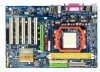
GA-MF3 Motherboard Layout KB_MS R_USB ATX_12V Socket AM2 COMA ATX COMB LPT USB LAN F_AUDIO IDE1 CLR_CMOS AUDIO CPU_FAN RTL AGP 8201 PCI1 AUX_IN CD_IN PCI2 CODEC PCI3 SUR_CEN PCI4 IT8716 PCI5 SPDIF_IO CI SYS_FAN DDRII1 DDRII2 IDE2 SATA0_SB SATA1_SB GA-MF3 BATTERY nVIDIA® - Gigabyte GA-MF3 | Manual - Page 8
Block Diagram AGP Slot 4X / 8X AGP CLK (66 MHz) AMD Socket AM2 CPU CPU CLK+/-(200 MHz) DDRII 667/533 MHz DIMM Dual Channel Memory Hyper Transport Bus 5 PCI PCI CLK (33 MHz) LAN RJ45 RTL8201 PCI Bus BIOS nVIDIA® nForce3 250 2 Serial ATA ATA33/66/100/133 IDE Channels LPC BUS Floppy LPT Port - Gigabyte GA-MF3 | Manual - Page 9
instructions below: 1. Please turn off the computer and unplug its power cord. 2. When handling the motherboard , avoid touching any metal leads or connectors. 3. It is best to wear an electrostatic discharge (ESD) cuff when handling electronic components (CPU motherboard problem manual - Gigabyte GA-MF3 | Manual - Page 10
English 1-2 Feature Summary CPU Front Side Bus Chipset LAN Audio Storage O.S Support Memory Expanstion Slots Internal Connectors Socket AM2 for AMD AthlonTM 64 FX / AthlonTM 64 X2 Dual-Core / AthlonTM 64 / SempronTM processor 1600 MHz nVIDIA® nForce3 250 Realtek RTL8201 phy (10/100 Mbit) - Gigabyte GA-MF3 | Manual - Page 11
CPU warning temperature CPU / System fan failure warning Supports CPU Smart Fan function (Note 2) 1 4 Mbit flash ROM Use of licensed AWARD BIOS Supports @BIOS Supports Download Center Supports Q-Flash Supports EasyTune (Note 3) Supports Xpress Install Supports Xpress Recovery2 Supports Xpress BIOS - Gigabyte GA-MF3 | Manual - Page 12
one finger down on the middle of the CPU and gently press the metal lever back into its original position. Please use extra care when installing the CPU. The CPU will not fit if positioned incorrectly. Rather than applying force, please change the positioning of the CPU. GA-MF3 Motherboard - 12 - - Gigabyte GA-MF3 | Manual - Page 13
paste on the surface of the CPU. Install all the CPU cooler components (Please refer to the cooler manual for detailed installation instructions). Fig.2 Please connect the CPU cooler power connector to the CPU_FAN connector located on the motherboard so that the CPU cooler can properly function to - Gigabyte GA-MF3 | Manual - Page 14
one direction. If you are unable to insert the module, please switch the direction. The motherboard supports DDRII memory modules, whereby BIOS will automatically detect memory capacity and specifications. Memory modules are designed so that they can be inserted only in one direction. The memory - Gigabyte GA-MF3 | Manual - Page 15
Memory Configuration The GA-MF3 supports the Dual Channel Technology. After operating the Dual Channel Technology, the bandwidth of Memory Bus will double. Due to CPU limitation, if you chips, and speed), you must install them into DIMM sockets of the same color. - 15 - Hardware Installation - Gigabyte GA-MF3 | Manual - Page 16
outlined below: 1. Read the related expansion card's instruction document before install the expansion card into the computer. on the computer, if necessary, setup BIOS utility of expansion card from BIOS. 8. Install related driver from the operating system. Installing a GA-MF3 Motherboard - 16 - - Gigabyte GA-MF3 | Manual - Page 17
supports USB controller. If your OS does not support USB controller, please contact OS vendor for possible patch or driver upgrade devices. LAN Port The provided Internet connection is Fast Ethernet, audio software to configure 2-/4-/6-channel audio functioning. - 17 - Hardware Installation - Gigabyte GA-MF3 | Manual - Page 18
6) IDE1 / IDE2 7) SATA0_SB / SATA1_SB 8) PWR_LED 9) BATTERY 10) F_PANEL 11) F_AUDIO 12) CD_IN 13) AUX_IN 14) SUR_CEN 15) SPDIF_IO 16) F_USB1 / F_USB2 17) CLR_CMOS 18) CI GA-MF3 Motherboard - 18 - - Gigabyte GA-MF3 | Manual - Page 19
all components and devices are properly installed. Align the power connector with its proper location on the motherboard and connect tightly. The ATX_12V power connector mainly supplies power to the CPU. If the ATX_12V power connector is not connected, the system will not start. Caution! Please use - Gigabyte GA-MF3 | Manual - Page 20
to connect the CPU/system fan cable to the CPU_FAN/SYS_FAN connector to prevent the CPU/system from overheating supported are: 360KB, 720KB, 1.2MB, 1.44MB and 2.88MB. Before attaching the FDD cable, please take note of the foolproof groove in the FDD connector. 33 1 34 2 GA-MF3 Motherboard - Gigabyte GA-MF3 | Manual - Page 21
other as Slave (for information on settings, please refer to the instructions located on the IDE device). Before attaching the IDE cable, please to 150MB/s transfer rate. Please refer to the BIOS setting for the Serial ATA and install the proper driver in order to work properly. 1 71 7 SATA0_SB - Gigabyte GA-MF3 | Manual - Page 22
Definition 1 MPD+ 1 2 MPD- 3 MPD- 9) BATTERY GA-MF3 Motherboard Danger of explosion if battery is incorrectly replaced. Replace only with the same or equivalent type recommended by the manufacturer. Dispose of used batteries according to the manufacturer's instructions. If you want to erase - Gigabyte GA-MF3 | Manual - Page 23
English 10) F_PANEL (Front Panel Jumper) Please connect the power LED, PC speaker, reset switch and power switch etc. of your chassis front panel to the F_PANEL connector according to the pin assignment below. Message LED/ Power/ Sleep LED Speaker Connector Power Switch MSG+ MSG- PW+ PWSPEAK+ - Gigabyte GA-MF3 | Manual - Page 24
6 7 8 9 10 Definition MIC GND MIC_BIAS Power Front Audio(R) Rear Audio(R)/Return R NC No Pin Front Audio(L) Rear Audio(L)/Return L 12) CD_IN (CD In Connector) Connect CD-ROM or DVD-ROM audio out to the connector. Pin No. Definition 1 1 CD-L 2 GND 3 GND 4 CD-R GA-MF3 Motherboard - 24 - - Gigabyte GA-MF3 | Manual - Page 25
out) to the connector. 1 Pin No. Definition 1 AUX-L 2 GND 3 GND 4 AUX-R 14) SUR_CEN (Surround Center Connector) Attach the connector of the Channel Audio Combo Kit (optional) to this connector. 51 62 Pin No. 1 2 3 4 5 6 Definition SUR OUTL SUR OUTR GND No Pin CENTER_OUT BASS_OUT - 25 - Gigabyte GA-MF3 | Manual - Page 26
SPDIF_IO (S/PDIF In/Out Connector) The S/PDIF output is capable of providing digital audio to external speakers or compressed AC3 data to an external Dolby Digital Decoder. 3 4 5 6 7 8 9 10 Definition Power (5V) Power (5V) USB DXUSB DyUSB DX+ USB Dy+ GND GND No Pin NC GA-MF3 Motherboard - 26 - - Gigabyte GA-MF3 | Manual - Page 27
Intrusion, Case Open) This 2-pin connector allows your system to detect if the chassis cover is removed. You can check the "Case Opened" status in BIOS Setup. Pin No. Definition 1 Signal 1 2 GND - 27 - Hardware Installation - Gigabyte GA-MF3 | Manual - Page 28
English GA-MF3 Motherboard - 28 - - Gigabyte GA-MF3 | Manual - Page 29
a new BIOS, either Gigabyte's Q-Flash or @BIOS utility can be used. Q-Flash allows the user to quickly and easily update or backup BIOS without entering the operating system. @BIOS is a Windows-based utility that does not require users to boot to DOS before upgrading BIOS but directly download and - Gigabyte GA-MF3 | Manual - Page 30
in the BIOS Setup when somehow the system is not stable as usual. This action makes the system reset to the default settings for stability. 3. The BIOS Setup menus described in this chapter are for reference only and may differ from the exact settings for your motherboard. GA-MF3 Motherboard - 30 - Gigabyte GA-MF3 | Manual - Page 31
This setup page includes all the items in standard compatible BIOS. „ Advanced BIOS Features This setup page includes all the items of Award temperature, voltage, fan speed, etc. „ MB Intelligent Tweaker (M.I.T.) This setup page is to control CPU clock and frequency ratio. „ Load Optimized Defaults - Gigabyte GA-MF3 | Manual - Page 32
On Floppy 3 Mode Support [1.44M, 3.5"] [None Manual User can manually BIOS to automatically detect IDE/SATA devices during POST (default) None Select this if no IDE/SATA devices are used and the system will skip the automatic detection step and allow for faster system start up. GA-MF3 Motherboard - Gigabyte GA-MF3 | Manual - Page 33
may be detected and you will be prompted. All Errors Whenever the BIOS detects a non-fatal error the system will be stopped. All, keyboard or disk error; it will stop for all other errors. Floppy 3 Mode Support (for Japan Area) Disabled Drive A Normal Floppy Drive. (Default value) Drive A - Gigabyte GA-MF3 | Manual - Page 34
. Note that BIOS can not tell from 720K, 1.2M or 1.44M drive type as they are all 80 tracks. Disabled BIOS will not search for the type of floppy disk drive by track number. Note that there will not be any warning message if the drive installed is 360K. (Default value) GA-MF3 Motherboard - 34 - Gigabyte GA-MF3 | Manual - Page 35
you to select the first initiation of the monitor display from which card when you install an AGP card and a PCI VGA card on the motherboard. AGP Set Init display first to AGP. PCI slot Set Init display first to PCI. (Default value) - 35 - Gigabyte GA-MF3 | Manual - Page 36
IDE DMA transfer Serial-ATA 2(Internal PHY) SATA DMA transfer USB Memory Type AC97 Audio On-Chip LAN(nVIDIA) OnBoard LAN Boot ROM Onboard Serial Port 1 Onboard Serial Port 2 Onboard Parallel Port Parallel Port Mode channel. It will operate in ATA mode. (Default value) GA-MF3 Motherboard - 36 - - Gigabyte GA-MF3 | Manual - Page 37
Boot ROM This function decide whether to invoke the boot ROM of the onboard LAN chip. Enabled Enable this function. Disabled Disable this function. (Default value) Onboard Serial Port 1 Auto BIOS will automatically setup the port 1 address. 3F8/IRQ4 Enable onboard Serial port 1 and address - Gigabyte GA-MF3 | Manual - Page 38
in legacy operating systems like MS-DOS. Enabled Enable support for USB mouse. Disabled Disable support for USB mouse. (Default value) Legacy USB storage detect POST. Enabled BIOS will scan all USB storage devices. (Default value) Disabled Disable this function. GA-MF3 Motherboard - 38 - - Gigabyte GA-MF3 | Manual - Page 39
to POWER ON system. If Resume by Alarm is Enabled. Day of Month Alarm : Everyday, 1~31 Time (hh: mm: ss) Alarm : (0~23) : (0~59) : (0~59) - 39 - BIOS Setup - Gigabyte GA-MF3 | Manual - Page 40
system, the system will be in "Off" state. (Default value) Full-On When AC-power back to the system, the system always in "On" state. GA-MF3 Motherboard - 40 - - Gigabyte GA-MF3 | Manual - Page 41
3,4,5,7,9,10,11,12,14,15 to PCI 1/PCI 5. Auto assign IRQ to PCI 2. (Default value) Set IRQ 3,4,5,7,9,10,11,12,14,15 to PCI 2. - 41 - BIOS Setup - Gigabyte GA-MF3 | Manual - Page 42
for it. (Default value) Voltage Set to Voltage when you use a CPU fan with a 3-pin fan power cable. PWM Set to PWM when you use a CPU fan with a 4-pin fan power cable. (Note) Whether the CPU Smart FAN Control function is supported will depend on the CPU you install. GA-MF3 Motherboard - 42 - - Gigabyte GA-MF3 | Manual - Page 43
only! CPU Voltage Control Supports adjustable CPU Vcore. The adjustable range is dependent on CPUs. (Default value: Normal) Please note that by overclocking your system through the increase of the CPU voltage, damage to the CPU or decrease in the CPU life expectancy may occur. - 43 - BIOS Setup - Gigabyte GA-MF3 | Manual - Page 44
" in Advance BIOS Features Menu, you will be prompted for the password every time the system is rebooted or any time you try to enter Setup Menu. If you select "Setup" at "Password Check" in Advance BIOS Features Menu, you will be prompted only when you try to enter Setup. GA-MF3 Motherboard - 44 - Gigabyte GA-MF3 | Manual - Page 45
Setup CMOS Setup Utility-Copyright (C) 1984-2006 Award Software ` Standard CMOS Features ` Advanced BIOS Features ` Integrated Peripherals ` Power Management Setup ` PnP/PCI Configurations ` PC Health Status ` MB Intelligent Tweaker(M.I.T.) Load Optimized Defaults Save to CMOS and EXITS(eYt S/Nu - Gigabyte GA-MF3 | Manual - Page 46
English GA-MF3 Motherboard - 46 - - Gigabyte GA-MF3 | Manual - Page 47
Installation Pictures below are shown in Windows XP. Insert the driver CD-title that came with your motherboard into your CD-ROM drive, the driver CD-title will auto start and show the installation guide. If not, please double click the CD-ROM device icon in "My computer", and execute the Setup - Gigabyte GA-MF3 | Manual - Page 48
English 3-2 Software Application This page displays all the tools that GIGABYTE developed and some free software. You can click an item to install it. 3-3 Software Information This page lists the contents of software and drivers in this CD-title. GA-MF3 Motherboard - 48 - - Gigabyte GA-MF3 | Manual - Page 49
English 3-4 Hardware Information This page lists all device you have for this motherboard. 3-5 Contact Us Please see the last page for details. - 49 - Drivers Installation - Gigabyte GA-MF3 | Manual - Page 50
English GA-MF3 Motherboard - 50 - - Gigabyte GA-MF3 | Manual - Page 51
button Toggles between Easy and Advance Mode Display panel of CPU frequency Shows the current functions status Log on to GIGABYTE website Display EasyTuneTM 5 Help file Quit or Minimize EasyTuneTM 5 software (Note) EasyTune 5 functions may vary depending on different motherboards. - 51 - Appendix - Gigabyte GA-MF3 | Manual - Page 52
At least 64M bytes of system memory 3. VESA-supported VGA cards How to use the Xpress Recovery2 Initial access Award Modular BIOS v6.00PG, An Energy Star Ally Copyright (C) 1984-2006, Award Software, Inc. GA-MF3 D12 . . . . :BIOS Setup/Q- drivers as well as software. GA-MF3 Motherboard - 52 - - Gigabyte GA-MF3 | Manual - Page 53
hard disk, so free space available on the not supported. 6. Does not support RAID/ driver CD before data backup. 2. It is normal that data backup takes longer time than data restoration. 3. Xpress Recovery2 is compliant with the GPL regulations. 4. On a few motherboards based on Nvidia chipsets, BIOS - Gigabyte GA-MF3 | Manual - Page 54
first. 1. Download the latest BIOS for your motherboard from Gigabyte's website. 2. Extract the BIOS file downloaded and save the BIOS file (the one with model name.Fxx. For example, 8KNXPU.Fba) to a floppy disk. 3. Reboot your PC and press Del to enter BIOS menu. The BIOS upgrading guides below are - Gigabyte GA-MF3 | Manual - Page 55
-Copyright (C) 1984-2004 Award Software Standard CMOS Features Advanced BIOS Features Integrated Peripherals Power Management Setup PnP/PCI Configurations PC Health Status MB Intelligent Tweaker(M.I.T.) ESC: Quit F8: Dual BIOS/Q-Flash Select Language Load Fail-Safe Defaults Load Optimized Defaults - Gigabyte GA-MF3 | Manual - Page 56
BIOS from Floppy Save Main BIOS to Floppy Save Backup BIOS to Floppy Enter : Run :Move ESC:Reset F10:Power Off Do not turn off power or reset your system at this stage!! After BIOS file is read, you'll see a confirmation dialog box asking you "Are you sure to update BIOS?" GA-MF3 Motherboard - Gigabyte GA-MF3 | Manual - Page 57
CPopleyasMe apirneRssOaMnyDkaetya tto cBoanctkiunpue Load Default Settings Save Settings to CMOS Q-Flash Utility Load Main BIOS from Floppy Load Backup BIOS from Floppy Save Main BIOS to Floppy Save Backup BIOS to Floppy Enter : Run :Move ESC:Reset F10:Power Off You can repeat Step 1 to - Gigabyte GA-MF3 | Manual - Page 58
Status MB Intelligent Tweaker(M.I.T.) ESC: Quit F8: Q-Flash Top Performance Load Fail-Safe Defaults Load Optimized Defaults Set Supervisor Password Set User Password Save & Exit Setup Exit Without Saving : Select Item F10: Save & Exit Setup Time, Date, Hard Disk Type... GA-MF3 Motherboard - 58 - Gigabyte GA-MF3 | Manual - Page 59
file you want to flash and press Enter. In this example, we only download one BIOS file to the floppy disk so only one BIOS file, 8GE800.F4, is listed. Please confirm again you have the correct BIOS file for your motherboard. Q-Flash Utility V1.30 Flash Type/Size SST 49LF003A 256K 8GE800.F4Keep - Gigabyte GA-MF3 | Manual - Page 60
/ Q-Flash 03/18/2003-I845GE-6A69YG01C-00 6. Press Del to enter BIOS menu after system reboots and load BIOS optimized defaults. See how to load BIOS optimized defaults, please kindly refer to Step 6 to 7 in Part One. Congratulation!! You have updated BIOS successfully!! GA-MF3 Motherboard - 60 - - Gigabyte GA-MF3 | Manual - Page 61
"Internet Update" icon b. Click "Update New BIOS" c. Please select "All Files" in dialog box while opening the old file. d. Please search for BIOS unzip file, downloading from internet or any other methods (such as: MF3.F1). e. Complete update process following the instruction. - 61 - Appendix - Gigabyte GA-MF3 | Manual - Page 62
in @BIOSTM server, please go onto Gigabyte's web site for downloading and updating it according to method II. IV. Please note that any interruption during updating will cause system unbooted. V. Do not use @BIOS and C.O.M. (Corporate Online Management) at the same time. GA-MF3 Motherboard - 62 - - Gigabyte GA-MF3 | Manual - Page 63
BIOS Setup. (3) Configure RAID set in RAID BIOS. (Note ) (4) Make a floppy disk containing the SATA controller driver. (Note ) (5) Install the SATA controller driver disk. (Note ) (c) Windows XP/2000 setup disk. (d) Driver CD for your motherboard. (Note ) (1) Installing SATA hard drive(s) in your - Gigabyte GA-MF3 | Manual - Page 64
Memory Type AC97 Audio On-Chip LAN(nVIDIA) OnBoard LAN Boot ROM Onboard BIOS Setup menus described in this section may not show the exact settings for your motherboard. The actual BIOS Setup menu options you will see shall depend on the motherboard you have and the BIOS version. GA-MF3 Motherboard - Gigabyte GA-MF3 | Manual - Page 65
Step 2: To boot from Windows installation CD-ROM, set First Boot Device under the Advanced BIOS Features menu to CDROM (Figure 3). CMOS Setup Utility-Copyright (C) 1984-2006 Award Software Advanced BIOS Features Hard Disk Boot Priority First Boot Device Second Boot Device Third Boot Device Boot - Gigabyte GA-MF3 | Manual - Page 66
BIOS setup utility. NVIDIA RAID IDE ROM BIOS . The supported RAID modes can manually set Free Disks Loc Disk Model Name 1.0.M ST3120026AS 1.1.M ST3120026AS Array Disks Loc Disk Model Name [ ] Add [ ] Del [F6] Back [F7] Finish [TAB] Navigate [ ] Select [ENTER] Popup Figure 5 GA-MF3 Motherboard - Gigabyte GA-MF3 | Manual - Page 67
Y to clear the data from the hard drives.) RAID Mode: Striping NVIDIA RAID Utility May 10 2004 - Define a New Array - Striping Block: Optimal Free Disks Loc Disk Model Name Clear disk daAtrar?ay Disks Loc Disk Model Name [Y[] Y]EASdd [N] 11N..01O..MM ST3120026AS ST3120026AS [ ] Del [F6 - Gigabyte GA-MF3 | Manual - Page 68
Nvidia RAID utility, press ESC in the main menu or Ctrl+X in the Array List screen. Now, you can proceed to install the SATA controller driver and operating system. GA-MF3 Motherboard - 68 - - Gigabyte GA-MF3 | Manual - Page 69
driver for the SATA controller from the motherboard driver CD-ROM to a floppy disk. See the instructions below about how to copy the driver in MS-DOS mode . (Note) Prepare a startup disk that has CD-ROM support an alternative system and insert the GIGABYTE motherboard driver CD-ROM. From the CDROM - Gigabyte GA-MF3 | Manual - Page 70
device manufacturer, press S. * If you do not have any device support disks from a mass storage device manufacturer, or do not want to specify additional mass storage devices for use with Windows, press ENTER. S=Specify Additional Device ENTER=Continue F3=Exit Figure 14 GA-MF3 Motherboard - 70 - - Gigabyte GA-MF3 | Manual - Page 71
=Select F3=Exit Figure 15 Windows Setup Setup will load support for the following mass storage device(s): NVIDIA RAID CLASS DRIVER (required) * To specify additional SCSI adapters, CD-ROM check the floppy disk or copy the correct SATA driver again from the motherboard driver CD. - 71 - Appendix - Gigabyte GA-MF3 | Manual - Page 72
have a device support disk from a mass storage device manufacturer, press S. * If you do not have any device support disks from a , the RAID driver will have to be installed under Windows once for that hard drive. After that, the driver will not have to be installed.) GA-MF3 Motherboard - 72 - - Gigabyte GA-MF3 | Manual - Page 73
or earphone to "Line Out." Line Out STEP 2: After installing the audio driver, you'll find a Sound Effect icon on the lower right hand taskbar. Click the icon to select the function. STEP 3: On the AC97 Audio Configuration menu, click the Speaker Configuration tab and select the 2-channel mode - Gigabyte GA-MF3 | Manual - Page 74
audio driver, you'll find a Sound Effect icon on the lower right hand taskbar. Click the icon to select the function. STEP 3: On the AC97 Audio the sound would be performed as stereo mode (2-channel output). Please select other settings (ex: Living Room) for 4-channel output. GA-MF3 Motherboard - - Gigabyte GA-MF3 | Manual - Page 75
to "Line Out",the rear channels to "Line In", and the Center/Subwoofer channels to "MIC In". MIC In Line Out STEP 2: After installing the audio driver, you'll find a Sound Effect icon on the lower right hand taskbar. Click the icon to select the function. Line In STEP 3: On the AC97 - Gigabyte GA-MF3 | Manual - Page 76
at the same time. "SURROUND-KIT" is included in the GIGABYTE unique "Audio Combo Kit" as picture. STEP 1: Secure the metal bracket of the"Surround Kit" to the chassis back panel with a screw. STEP 2: Connect the "SURROUND-KIT" cable to the SUR_CEN connector on the M/B. GA-MF3 Motherboard - 76 - - Gigabyte GA-MF3 | Manual - Page 77
panel's "Line Out", the rear channels to SURROUND-KIT's REAR R/L, and the Center/Subwoofer channels to SURROUND-KIT's SUB CENTER. STEP 4: After installing the audio driver, you'll find a Sound Effect icon on the lower right hand taskbar. Click the icon to select the function. STEP 5: On the AC97 - Gigabyte GA-MF3 | Manual - Page 78
Device (Optional Device) A "S/PDIF output" connector is available on the motherboard. Cable with rear bracket could link to the "S/PDIF output" connector (As , and fix it with screw. 2. Connect S/PDIF device to the motherboard. 3. Connect S/PDIF to the S/PDIF decoder. GA-MF3 Motherboard - 78 - - Gigabyte GA-MF3 | Manual - Page 79
Troubleshooting Below is a collection of general asked questions. To check general asked questions based on a specific motherboard model, please log on to GIGABYTE's website. Question 1: I cannot see some options that were included in previous BIOS after updating BIOS the manual. If cord from MB. 3. - Gigabyte GA-MF3 | Manual - Page 80
English GA-MF3 Motherboard - 80 - - Gigabyte GA-MF3 | Manual - Page 81
- 81 - Appendix English - Gigabyte GA-MF3 | Manual - Page 82
English GA-MF3 Motherboard - 82 - - Gigabyte GA-MF3 | Manual - Page 83
- 83 - Appendix English - Gigabyte GA-MF3 | Manual - Page 84
English GA-MF3 Motherboard - 84 - - Gigabyte GA-MF3 | Manual - Page 85
- 85 - Appendix English - Gigabyte GA-MF3 | Manual - Page 86
ext. 814 Xian TEL: +86-29-85531943 FAX: +86-29-85539821 Shenyang TEL: +86-24-83992901 FAX: +86-24-83992909 y India GIGABYTE TECHNOLOGY (INDIA) LIMITED WEB address : http://www.gigabyte.in y Australia GIGABYTE TECHNOLOGY PTY. LTD. WEB address : http://www.gigabyte.com.au GA-MF3 Motherboard - 86 - - Gigabyte GA-MF3 | Manual - Page 87
WEB address : http://www.gigabyte.com.ro y Serbia & Montenegro Representative Office Of GIGA-BYTE Technology Co., Ltd. in SERBIA & MONTENEGRO WEB address : http://www.gigabyte.co.yu y GIGABYTE Global Service System To submit a technical or non-technical (Sales/ Marketing) question, please link - Gigabyte GA-MF3 | Manual - Page 88
- 88 -
-
 1
1 -
 2
2 -
 3
3 -
 4
4 -
 5
5 -
 6
6 -
 7
7 -
8
-
9
-
10
-
11
-
12
-
13
-
14
-
15
-
16
-
17
-
18
-
19
-
20
-
21
-
22
-
23
-
24
-
25
-
26
-
27
-
28
-
29
-
30
-
31
-
32
-
33
-
34
-
35
-
36
-
37
-
38
-
39
-
40
-
41
-
42
-
43
-
44
-
45
-
46
-
47
-
48
-
49
-
50
-
51
-
52
-
53
-
54
-
55
-
56
-
57
-
58
-
59
-
60
-
61
-
62
-
63
-
64
-
65
-
66
-
67
-
68
-
69
-
70
-
71
-
72
-
73
-
74
-
75
-
76
-
77
-
78
-
79
-
80
-
81
-
82
-
83
-
84
-
85
-
86
-
87
-
88
 |
 |

GA-MF3
AMD Socket AM2 Processor Motherboard
User's Manual
Rev. 1002
12ME-MF3-1002R
*
The WEEE marking on the product indicates this product must not be disposed of with user's other household waste
and must be handed over to a designated collection point for the recycling of waste electrical and electronic equipment!!
*
The WEEE marking applies only in European Union's member states.