Gigabyte GA-P31-DS3L Manual
Gigabyte GA-P31-DS3L Manual
 |
UPC - 818313004253
View all Gigabyte GA-P31-DS3L manuals
Add to My Manuals
Save this manual to your list of manuals |
Gigabyte GA-P31-DS3L manual content summary:
- Gigabyte GA-P31-DS3L | Manual - Page 1
GA-P31-DS3/ GA-P31-DS3L/ GA-P31-S3L LGA775 socket motherboard for Intel® CoreTM processor family/ Intel® Pentium® processor family/Intel® Celeron® processor family User's Manual Rev. 1001 12ME-P31DS3-1001R * The WEEE marking on the product indicates this product must not be disposed of with user's - Gigabyte GA-P31-DS3L | Manual - Page 2
Motherboard GA-P31-DS3/GA-P31-DS3L/GA-P31-S3L Jul. 20, 2007 Motherboard GA-P31-DS3/GA-P31-DS3L/ GA-P31-S3L Jul. 20, 2007 - Gigabyte GA-P31-DS3L | Manual - Page 3
with the product. „ For detailed product information, carefully read the User's Manual. „ For instructions on how to use GIGABYTE's unique features, read or download the information on/from the Support\Motherboard\Technology Guide page on our website. For product-related information, check on our - Gigabyte GA-P31-DS3L | Manual - Page 4
Contents ...6 OptionalItems ...6 GA-P31-DS3/DS3L/S3L Motherboard Layout 7 Block Diagram ...8 Chapter 1 Hardware Installation 9 1-1 Installation Precautions 9 1-2 Product Specifications 10 1-3 Installing the CPU and CPU Cooler 13 1-3-1 Installing the CPU 13 1-3-2 Installing the CPU Cooler 15 - Gigabyte GA-P31-DS3L | Manual - Page 5
Chipset Drivers 53 3-2 Software Applications 54 3-3 Driver CD Information 54 3-4 Hardware Information 55 3-5 Contact Us ...55 Chapter 4 Unique Features 57 4-1 Xpress Recovery2 57 4-2 BIOS Update Utilities 62 4-2-1 Updating the BIOS with the Q-Flash Utility 62 4-2-2 Updating the BIOS - Gigabyte GA-P31-DS3L | Manual - Page 6
GA-P31-DS3, GA-P31-DS3L or GA-P31-S3L motherboard Motherboard driver disk User's Manual Quick Installation Guide Intel® LGA775 CPU Installation Guide to change without notice. Optional Items 2-port USB 2.0 bracket (Part No. 12CR1-1UB030-51/R) 4-port USB 2.0 bracket (Part No. 12CR1-1UB030-21/R) - Gigabyte GA-P31-DS3L | Manual - Page 7
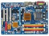
GA-P31-DS3/DS3L/S3L Motherboard Layout KB_MS COAXIAL OPTICAL ATX_12V LGA775 CPU_FAN COMA LPT PWR_FAN GA-P31-DS3/DS3L/S3L USB USB LAN F_AUDIO Intel® P31 AUDIO SYS_FAN1 DDRII1 PCIE_3 ATX CD_IN RTL8111B PCIE_16 DDRII2 DDRII3 DDRII4 PCIE_1 CLR_CMOS SPDIF_O CODEC PCIE_2 PCI1 - Gigabyte GA-P31-DS3L | Manual - Page 8
x1 x 1 x1 x1 PCIe CLK (100 MHz) PCI Bus Host Interface DDR2 800/667 MHz Intel® P31 Dual Channel Memory MCH CLK (333/266/200 MHz) Intel® ICH7 CODEC BIOS ATA-100/66/33 IDE Channel 4 SATA 3Gb/s 8 USB Ports IT8718 Floppy LPT Port COM Port PS/2 KB/Mouse Surround Speaker Out Center/Subwoofer - Gigabyte GA-P31-DS3L | Manual - Page 9
user's manual and follow these procedures: • Prior to installation, do not remove or break motherboard wrist strap when handling electronic components such as a motherboard, CPU or memory. If you do not have an the user. • If you are uncertain about any installation steps or have a problem related - Gigabyte GA-P31-DS3L | Manual - Page 10
in the LGA 775 package (Go to GIGABYTE's website for the latest CPU support list.) Š Support for Intel® Hyper-Threading Technology Š L2 cache varies with CPU Š 1333/1066/800 MHz FSB Š North Bridge: Intel® P31 Express Chipset Š South Bridge: Intel® ICH7 Š 4 x 1.8V DDR2 DIMM sockets supporting up to - Gigabyte GA-P31-DS3L | Manual - Page 11
USB 2.0/1.1 ports Š 1 x RJ-45 port Š 6 x audio CPU/System temperature detection Š CPU/System/Power fan speed detection Š CPU overheating warning Š CPU/System/Power fan fail warning Š CPU fan speed control BIOS Š 1 x 4 Mbit flash Š Use of licensed AWARD BIOS Š PnP 1.0a, DMI 2.0, SM BIOS - Gigabyte GA-P31-DS3L | Manual - Page 12
Factor Š Support for @BIOS Š Support for Download Center Š Support for Q-Flash Š Support for EasyTune (Note 3) Š Support for Xpress Install Š Support for Xpress Recovery2 Š Support for Virtual Dual BIOS Š Norton Internet Security (OEM version) Š Support for Microsoft® Windows® Vista/XP/2000 Š ATX - Gigabyte GA-P31-DS3L | Manual - Page 13
enabled (Refer to Chapter 2, "BIOS Setup," "Advanced BIOS Features," for instructions on enabling the HT Technology.) 1-3-1 Installing the CPU A. Locate the alignment keys on the motherboard CPU socket and the notches on the CPU. LGA775 CPU Socket Alignment Key LGA 775 CPU Alignment Key Pin One - Gigabyte GA-P31-DS3L | Manual - Page 14
corner of the CPU socket (or you may align the CPU notches with the socket alignment keys) and gently insert the CPU into position. Step 5: Once the CPU is properly inserted, replace the load plate and push the CPU socket lever back into its locked position. GA-P31-DS3/DS3L/S3L Motherboard - 14 - - Gigabyte GA-P31-DS3L | Manual - Page 15
. Check that the Male and Female push pins are joined closely. (Refer to your CPU cooler installation manual for instructions on installing the cooler.) Step 5: After the installation, check the back of the motherboard. If the push pin is inserted as the picture above, the installation is complete - Gigabyte GA-P31-DS3L | Manual - Page 16
table for optimum performance. 3. Because of chipset limitations, do not populate both DIMM sockets of the same channel (e.g. DDRII1 and DDRII2) with double-sided memory modules to prevent system's failure to start or incorrect detection of memory modules. GA-P31-DS3/DS3L/S3L Motherboard - 16 - - Gigabyte GA-P31-DS3L | Manual - Page 17
power outlet to prevent damage to the memory module. DDR2 DIMMs are not compatible to DDR DIMMs. Be sure to install DDR2 DIMMs on this motherboard. Notch DDR2 DIMM A DDR2 memory module has a notch, so it can only fit in one direction. Follow the steps below to correctly install your memory - Gigabyte GA-P31-DS3L | Manual - Page 18
. Make sure the graphics card is locked by the latch at the end of the PCI Express x16 slot. • Removing the Card: Press the white latch at the end of the PCI Express x16 slot to release the card and then pull the card straight up from the slot. GA-P31-DS3/DS3L/S3L Motherboard - 18 - - Gigabyte GA-P31-DS3L | Manual - Page 19
audio in connector. Serial Port Use the serial port to connect devices such as a mouse, modem or other peripherals. USB Port The USB port supports the USB 2.0/1.1 specification. Use this port for USB devices such as an USB keyboard/mouse, USB printer, USB flash it from the motherboard. • When - Gigabyte GA-P31-DS3L | Manual - Page 20
different functions via the audio software. Only microphones still MUST be connected to the default Mic in jack ( ). Refer to the instructions on setting up a 2/4/5.1/ 7.1-channel audio configuration in Chapter 5, "Configuring 2/4/5.1/7.1-Channel Audio." GA-P31-DS3/DS3L/S3L Motherboard - 20 - - Gigabyte GA-P31-DS3L | Manual - Page 21
devices. • After installing the device and before turning on the computer, make sure the device cable has been securely attached to the connector on the motherboard. - 21 - Hardware Installation - Gigabyte GA-P31-DS3L | Manual - Page 22
to the power connector in the correct orientation. The 12V power connector mainly supplies power to the CPU. If the 12V power connector is not connected, the computer will not start. • To meet 5V +5V +5V (Only for 2x12-pinATX) GND (Only for 2x12-pin ATX) GA-P31-DS3/DS3L/S3L Motherboard - 22 - - Gigabyte GA-P31-DS3L | Manual - Page 23
wire indicates a positive connection and requires a +12V voltage. The black connector wire is the ground wire. The motherboard supports CPU fan speed control, which requires the use of a CPU fan with fan speed control design. For optimum heat dissipation, it is recommended that a system fan be - Gigabyte GA-P31-DS3L | Manual - Page 24
master/slave settings for the IDE devices, read the instructions from the device manufacturers.) 2 40 1 39 9) supports a single SATA device. SATAII0 SATAII2 7 17 1 1 71 7 SATAII1 SATAII3 Pin No. 1 2 3 4 5 6 7 Definition GND TXP TXN GND RXN RXP GND GA-P31-DS3/DS3L/S3L Motherboard - Gigabyte GA-P31-DS3L | Manual - Page 25
10 NC • The front panel audio header supports HD audio by default. If your chassis provides an AC'97 front panel audio module, refer to the instructions on how to activate AC'97 functioninality via the audio software in Chapter 5, "Configuring 2/4/5.1/7.1-Channel Audio." • When using an AC'97 - Gigabyte GA-P31-DS3L | Manual - Page 26
panel module mainly consists of power switch, reset switch, power LED, hard drive activity LED, speaker and etc. When connecting your chassis front panel module to this header, make sure the wire assignments and the pin assignments are matched correctly. GA-P31-DS3/DS3L/S3L Motherboard - 26 - - Gigabyte GA-P31-DS3L | Manual - Page 27
the header. Pin No. Definition 1 1 CD-L 2 GND 3 GND 4 CD-R 14) SPDIF_I (S/PDIF In Header) This header supports digital S/PDIF in and can connect to an audio device that supports digital audio out via an optional S/PDIF in cable. For purchasing the optional S/PDIF in cable, please contact - Gigabyte GA-P31-DS3L | Manual - Page 28
8 GND 9 No Pin 10 NC • Do not plug the IEEE 1394 bracket (2x5-pin) cable into the USB header. • Prior to installing the USB bracket, be sure to turn off your computer and unplug the power cord from the power outlet to prevent damage to the USB bracket. GA-P31-DS3/DS3L/S3L Motherboard - 28 - - Gigabyte GA-P31-DS3L | Manual - Page 29
the CMOS values and before turning on your computer, be sure to remove the jumper cap from the jumper. Failure to do so may cause damage to the motherboard. • After system restart, go to BIOS Setup to load factory defaults (select Load Optimized Defaults) or manually configure the BIOS settings - Gigabyte GA-P31-DS3L | Manual - Page 30
(such as BIOS configurations, date, and time information) in the CMOS when the computer is turned off. Replace the battery when the battery voltage drops to a low level, or the CMOS values may not be handled in accordance with local environmental regulations. GA-P31-DS3/DS3L/S3L Motherboard - 30 - - Gigabyte GA-P31-DS3L | Manual - Page 31
the GIGABYTE Q-Flash or @BIOS utility. • Q-Flash allows the user to quickly and easily upgrade or back up BIOS without entering the operating system. • @BIOS is a Windows-based utility that searches and downloads the latest version of BIOS from the Internet and updates the BIOS. For instructions on - Gigabyte GA-P31-DS3L | Manual - Page 32
device boot order will still be based on BIOS Setup settings. You can access Boot Menu again to change the first boot device setting as needed. : Q-Flash Press the key to access the Q-Flash utility directly without having to enter BIOS Setup first. GA-P31-DS3/DS3L/S3L Motherboard - 32 - Gigabyte GA-P31-DS3L | Manual - Page 33
Sample BIOS Version: GA-P31-DS3 E14) CMOS Setup Utility-Copyright (C) 1984-2007 Award Software ` Standard CMOS Features ` Advanced BIOS Flash utility Display system information Save all the changes and exit the BIOS Setup program Save CMOS to BIOS Load CMOS from BIOS - Gigabyte GA-P31-DS3L | Manual - Page 34
exit BIOS Setup. (Pressing can also carry out this task.) „ Exit Without Saving Abandon all changes and the previous settings remain in effect. Pressing to the confirmation message will exit BIOS Setup. (Pressing can also carry out this task.) GA-P31-DS3/DS3L/S3L Motherboard - 34 - Gigabyte GA-P31-DS3L | Manual - Page 35
Award Software Standard CMOS Features Tue, Jul 3 2007 22:31:24 Item Help Menu Level` ` IDE Channel 0 Master ` IDE Channel 0 Slave ` IDE Channel 2 Master ` IDE Channel 2 Slave ` IDE Channel 3 Master ` IDE Channel 3 Slave [None] [None] [None] [None] [None] [None] Drive A Floppy 3 Mode Support - Gigabyte GA-P31-DS3L | Manual - Page 36
are determined by the BIOS POST. Base Memory Also called conventional memory. Typically, 640 KB will be reserved for the MS-DOS operating system. Extended Memory The amount of extended memory. Total Memory The total amount of memory installed on the system. GA-P31-DS3/DS3L/S3L Motherboard - 36 - - Gigabyte GA-P31-DS3L | Manual - Page 37
English 2-4 Advanced BIOS Features CMOS Setup Utility-Copyright (C) 1984-2007 Award Software Advanced BIOS Features ` Hard Disk Boot Priority First Boot Device Second Boot Device Third Boot Device Password Check HDD S.M.A.R.T. Capability CPU Hyper-Threading (Note) Limit CPUID Max. to 3 (Note) No- - Gigabyte GA-P31-DS3L | Manual - Page 38
whether to display the GIGABYTE Logo at system startup. graphics card as the first display. (Note) This item is present only if you install a CPU that supports this feature. For more information about Intel CPUs' unique features, please visit Intel's website. GA-P31-DS3/DS3L/S3L Motherboard - Gigabyte GA-P31-DS3L | Manual - Page 39
CMOS Setup Utility-Copyright (C) 1984-2007 Award Software Integrated Peripherals On-Chip Primary PCI IDE On-Chip SATA Mode x PATA IDE Set to SATA Port 0/2 Set to SATA Port 1/3 Set to USB Controller USB 2.0 Controller USB Keyboard Support USB Mouse Support Legacy USB BIOS you can manually re-configure - Gigabyte GA-P31-DS3L | Manual - Page 40
following information for diagnosing your LAN cable: When No LAN Cable Is Attached... If no LAN cable is attached to the motherboard, the Status fields of all four pairs of wires will show Open and the Length fields show 0.0m, as shown in the figure above. GA-P31-DS3/DS3L/S3L Motherboard - 40 - - Gigabyte GA-P31-DS3L | Manual - Page 41
will operate at a normal speed of 10/100/1000Mbps in Windows mode or when the LAN Boot ROM is activated. When a Cable Problem Occurs... If a cable problem occurs on a specified pair of wires, the Status field will Enhanced Parallel Port), ECP (Extended Capabilities Port), ECP+EPP. - 41 - BIOS Setup - Gigabyte GA-P31-DS3L | Manual - Page 42
lead. (Default: Enabled) Power On by Ring Allows the system to be awakened from an ACPI sleep state by a wake-up signal from a modem that supports wake-up function. (Default: Enabled) (Note) Supported on Windows® Vista® operating system only. GA-P31-DS3/DS3L/S3L Motherboard - 42 - - Gigabyte GA-P31-DS3L | Manual - Page 43
the date and time as following: Date (of Month) Alarm : Turn on the system at a specific time on each day or on a specific day in a month. Time (hh: mm: ss) Alarm : Set the time at which the the return of the AC power. (Note) Supported on Windows® Vista® operating system only. - 43 - BIOS Setup - Gigabyte GA-P31-DS3L | Manual - Page 44
,15 to the first PCI slot. BIOS auto-assigns IRQ to the second PCI slot. (Default) Assigns IRQ 3,4,5,7,9,10,11,12,14,15 to the second PCI slot. BIOS auto-assigns IRQ to the third PCI slot. (Default) Assigns IRQ 3,4,5,7,9,10,11,12,14,15 to the third PCI slot. GA-P31-DS3/DS3L/S3L Motherboard - 44 - - Gigabyte GA-P31-DS3L | Manual - Page 45
Status CMOS Setup Utility-Copyright (C) 1984-2007 Award Software PC Health Status Reset Case Open Status Case Opened Vcore DDR18V +3.3V +12V Current System Temperature Current CPU Temperature Current CPU FAN Speed Current SYSTEM FAN Speed Current POWER FAN Speed CPU Warning Temperature CPU FAN - Gigabyte GA-P31-DS3L | Manual - Page 46
PWM mode for a 4-pin CPU fan. Note: The Voltage mode can be set for a 3-pin CPU fan or a 4-pin CPU fan. However, for a 4-pin CPU fan that is not designed following Intel PWM fan specifications, selecting PWM mode may not effectively reduce the fan speed. GA-P31-DS3/DS3L/S3L Motherboard - 46 - - Gigabyte GA-P31-DS3L | Manual - Page 47
: If your system fails to boot after overclocking, please wait for 20 seconds to allow for automated system reboot, or clear the CMOS values to reset the board to default values. (Default: Disabled) CPU Host Frequency (Mhz) Allows you to manually set the CPU host frequency. This item is configurable - Gigabyte GA-P31-DS3L | Manual - Page 48
Timing Configuration 2. System Voltage Control Determines whether to manually set the system voltages. Auto lets BIOS automatically set the system voltages as required. Manual allows all voltage control items below to be configurable. (Default: Manual) GA-P31-DS3/DS3L/S3L Motherboard - 48 - - Gigabyte GA-P31-DS3L | Manual - Page 49
the CPU voltage as required. The adjustable range is dependent on the CPU being installed. (Default: Normal) Note: Increasing CPU voltage may result in damage to your CPU or reduce the useful life of the CPU. Normal CPU Vcore Displays the normal operating voltage of your CPU. - 49 - BIOS Setup - Gigabyte GA-P31-DS3L | Manual - Page 50
on this item and then press the key to load the optimal BIOS default settings. The BIOS defaults settings helps the system to operate in optimum state. Always load the Optimized defaults after updating the BIOS or after clearing the CMOS values. GA-P31-DS3/DS3L/S3L Motherboard - 50 - - Gigabyte GA-P31-DS3L | Manual - Page 51
Fail-Safe Defaults Load Optimized Defaults Set Supervisor Password Set User Password Save & Exit Setup Exit Without Saving ESC: Quit F8: Q-Flash KLJI: Select Item F10: Save & Exit Setup F11: Save CMOS to BIOS F12: Load CMOS from BIOS Change/Set/Disable Password Press on this item and - Gigabyte GA-P31-DS3L | Manual - Page 52
F11: Save CMOS to BIOS F12: Load CMOS from BIOS Abandon all Data Press on this item and press the key. This exits the BIOS Setup without saving the changes made in BIOS Setup to the CMOS. Press or to return to the BIOS Setup Main Menu. GA-P31-DS3/DS3L/S3L Motherboard - 52 - Gigabyte GA-P31-DS3L | Manual - Page 53
other drivers. • After the drivers are installed, follow the onscreen instructions to restart your system. You can install other applications included in the motherboard driver disk. • For USB 2.0 driver support under the Windows XP operating system, please install the Windows XP Service Pack - Gigabyte GA-P31-DS3L | Manual - Page 54
the tools and applications that GIGABYTE develops and some free software. You may press the Install button following an item to install it. 3-3 Driver CD Information This page provides information about the drivers, applications and tools in this driver disk. GA-P31-DS3/DS3L/S3L Motherboard - 54 - - Gigabyte GA-P31-DS3L | Manual - Page 55
English 3-4 Hardware Information This page provides information about the hardware devices on this motherboard. 3-5 Contact Us Check the contacts information of the GIGABYTE headquarter in Taiwan and the overseas branch offices on the last page of this manual. - 55 - Drivers Installation - Gigabyte GA-P31-DS3L | Manual - Page 56
English GA-P31-DS3/DS3L/S3L Motherboard - 56 - - Gigabyte GA-P31-DS3L | Manual - Page 57
graphics card • Windows® 2000 with SP3 or later; Windows® XP with SP1 or later • Xpress Recovery and Xpress Recovery2 are different utilities. For example, a backup file created with Xpress Recovery cannot be restored using Xpress Recovery2. • USB hard drives are not supported. • Hard drives in RAID - Gigabyte GA-P31-DS3L | Manual - Page 58
Windows XP as the example operating system.) A. Installing Windows XP and Partitioning the Hard Drive 1. Set CD-ROM drive as the first boot device under "Advanced BIOS Features" in the BIOS begin the installation of the operating system (Figure 3). Figure 3 GA-P31-DS3/DS3L/S3L Motherboard - 58 - - Gigabyte GA-P31-DS3L | Manual - Page 59
Figure 4 Figure 5 5. If your hard drive is not properly partitioned before you install the operating system, you may create new partitions using free space on your hard drive (Figure 6, 7). However, if Disk Management shows the hard drive only contains the System partition without any unallocated - Gigabyte GA-P31-DS3L | Manual - Page 60
Software, Inc. Intel P31 BIOS for P31-DS3 E14 . . . . : BIOS Setup/Q-Flash : XpressRecovery2 : Boot Menu : Qflash 07/02/2007-P31 to Disk Management to check disk allocation. Figure 12 GA-P31-DS3/DS3L/S3L Motherboard Xpress Recovery2 will automatically create a new partition to - Gigabyte GA-P31-DS3L | Manual - Page 61
English D. Using the Restore Function in Xpress Recovery2 Select RESTORE to restore the backup to your hard drive in case the system breaks down. The RESTORE option will not be present if no backup is created before (Figure 13, 14). Figure 13 Figure 14 E. Removing the Backup 1. If you wish to - Gigabyte GA-P31-DS3L | Manual - Page 62
for P31-DS3 E14 . . . . : BIOS Setup/Q-Flash : XpressRecovery2 : Boot Menu : Qflash 07/02/2007-P31-ICH7-6A79OG0WC-00 Because BIOS flashing is potentially risky, please do it with caution. Inadequate BIOS flashing may result in system malfunction. GA-P31-DS3/DS3L/S3L Motherboard - Gigabyte GA-P31-DS3L | Manual - Page 63
use the up or down arrow key to select Update BIOS from Drive and press . • The Save Main BIOS to Drive option allows you to save the current BIOS file. • Q-Flash only supports USB flash drive or hard drives using FAT32/16/12 file system. • If the BIOS update file is saved to a hard drive in - Gigabyte GA-P31-DS3L | Manual - Page 64
F11: Save CMOS to BIOS F12: Load CMOS from BIOS Load Optimized Defaults Press to load BIOS defaults Step 6: Select Save & Exit Setup and then press to save settings to CMOS and exit BIOS Setup. The procedure is complete after the system restarts. GA-P31-DS3/DS3L/S3L Motherboard - 64 - - Gigabyte GA-P31-DS3L | Manual - Page 65
BIOS flashing. B. Installing and Using @BIOS: Use the motherboard driver disk included with the motherboard to install @BIOS. • Installing the @BIOS utility. • Accessing the @BIOS utility. Select @BIOS and click Install. Click Start>Programs>GIGABYTE>@BIOS C. Options and Instructions - Gigabyte GA-P31-DS3L | Manual - Page 66
your motherboard model. Updating the BIOS with an incorrect BIOS file could result in an unbootable system. Step 4: As the system boots, press to enter the BIOS Setup program. Select Load Optimized Defaults and press to load BIOS defaults. GA-P31-DS3/DS3L/S3L Motherboard - 66 - Gigabyte GA-P31-DS3L | Manual - Page 67
the BIOS Setup program. EasyTune 5 provides the following functions (Note 1): overclocking/overvoltage, C.I.A./ M.I.B. (Note 2), smart fan control, and hardware monitoring and warning. (For instructions on using EasyTune5, read or download the information on/from the Support\Motherboard\Utility - Gigabyte GA-P31-DS3L | Manual - Page 68
or spin box. Click Apply and then OK to turn on ReadyBoost. • The USB flash drive must have at least 256 MB of space. • The recommended amount of memory to use for ReadyBoost acceleration is one to three times the amount of RAM installed in your computer. GA-P31-DS3/DS3L/S3L Motherboard - 68 - - Gigabyte GA-P31-DS3L | Manual - Page 69
Before installing the audio driver, make sure the "Microsoft UAA Bus driver for High Definition Audio" has been installed from the motherboard driver disk and your operating system has been updated with the latest Service Pack for Windows. (Note) 2/4/5.1/7.1 Channel Audio Configurations: Refer to - Gigabyte GA-P31-DS3L | Manual - Page 70
front panel jack detection check box. Click OK to activiate the AC'97 functionality. When using an AC'97 front panel audio module, you can only have audio signals present on either the front or the back panel audio connections, but not both at the same time. GA-P31-DS3/DS3L/S3L Motherboard - 70 - - Gigabyte GA-P31-DS3L | Manual - Page 71
In: The S/PDIF in jacks allow you to input digital audio signals to the computer for audio processing. A. Installing the S/PDIF In Cable: Step 1: First, attach the connector at the end of the cable to the SPDIF_IN header on your motherboard. Step 2: Secure the metal bracket to the chassis back - Gigabyte GA-P31-DS3L | Manual - Page 72
English S/PDIF Out: The S/PDIF out jacks can transmit audio signals to an external decoder for decoding to get the best audio quality. B. Conneting a S/PDIF out Cable Connect a S/PDIF coaxial cable ) the output source. Click OK to complete the configuration. GA-P31-DS3/DS3L/S3L Motherboard - 72 - - Gigabyte GA-P31-DS3L | Manual - Page 73
English 5-1-3 Configuring Microphone Recording Step 1: After installing the audio driver, the Audio Manager icon will appear in your system tray. Double-click the icon to access the Audio Control Panel. Step 2: Connect your microphone to the Mic in jack (pink) on the back panel or the Line in jack - Gigabyte GA-P31-DS3L | Manual - Page 74
device list, select Realtek HD Audio Input. Then set the recording sound level properly. Do NOT mute the recording sound, or you will not hear any sound when playing back the recording you just made. Select Realtek HD Audio Input in the Mixer devie list GA-P31-DS3/DS3L/S3L Motherboard Recording - Gigabyte GA-P31-DS3L | Manual - Page 75
, point to Programs, point to Accessories, point to Entertainment, and then click Sound Recorder to begin the sound recording. 5-1-4 Using the Sound Recorder Recording the Sound: 1. Make sure you have connected the audio input device (e.g. microphone) to the computer. 2. On the File menu, choose New - Gigabyte GA-P31-DS3L | Manual - Page 76
2 short: CMOS setting error 1 long, 1 short: Memory or motherboard error 1 long, 2 short: Monitor or graphics card error 1 long, 3 short: Keyboard error 1 long, 9 short: BIOS ROM error Continuous long beeps: Graphics card not inserted properly Continuous short beeps: Power error GA-P31-DS3/DS3L/S3L - Gigabyte GA-P31-DS3L | Manual - Page 77
Procedure If you encounter any troubles during system startup, follow the troubleshooting procedure below to solve the problem. START Turn off the power. Remove all peripherals, connecting cables, and power cord etc. Make sure the motherboard does not short-circuit with the chassis or - Gigabyte GA-P31-DS3L | Manual - Page 78
. END If the procedure above is unable to solve your problem, contact the place of purchase or local dealer for help. Or go to the Support\Technical Service Zone page to submit your question. Our customer service staff will reply you as soon as possible. GA-P31-DS3/DS3L/S3L Motherboard - 78 - - Gigabyte GA-P31-DS3L | Manual - Page 79
- 79 - Appendix English - Gigabyte GA-P31-DS3L | Manual - Page 80
English GA-P31-DS3/DS3L/S3L Motherboard - 80 - - Gigabyte GA-P31-DS3L | Manual - Page 81
- 81 - Appendix English - Gigabyte GA-P31-DS3L | Manual - Page 82
: +86-24-83992901 FAX: +86-24-83992909 India GIGABYTE TECHNOLOGY (INDIA) LIMITED WEB address : http://www.giga-byte.co.in/ Saudi Arabia WEB address : http://www.gigabyte.com.sa Australia GIGABYTE TECHNOLOGY PTY. LTD. WEB address : http://www.gigabyte.com.au GA-P31-DS3/DS3L/S3L Motherboard - 82 - - Gigabyte GA-P31-DS3L | Manual - Page 83
.co.yu You may go to the GIGABYTE website, select your language in the language list on the top right corner of the website. GIGABYTE Global Service System To submit a technical or non-technical (Sales/ Marketing) question, please link to : http://ggts.gigabyte.com.tw Then select your language to - Gigabyte GA-P31-DS3L | Manual - Page 84
- 84 -
-
 1
1 -
 2
2 -
 3
3 -
 4
4 -
 5
5 -
 6
6 -
 7
7 -
8
-
9
-
10
-
11
-
12
-
13
-
14
-
15
-
16
-
17
-
18
-
19
-
20
-
21
-
22
-
23
-
24
-
25
-
26
-
27
-
28
-
29
-
30
-
31
-
32
-
33
-
34
-
35
-
36
-
37
-
38
-
39
-
40
-
41
-
42
-
43
-
44
-
45
-
46
-
47
-
48
-
49
-
50
-
51
-
52
-
53
-
54
-
55
-
56
-
57
-
58
-
59
-
60
-
61
-
62
-
63
-
64
-
65
-
66
-
67
-
68
-
69
-
70
-
71
-
72
-
73
-
74
-
75
-
76
-
77
-
78
-
79
-
80
-
81
-
82
-
83
-
84
 |
 |

GA-P31-DS3/
GA-P31-DS3L/
GA-P31-S3L
LGA775 socket motherboard for Intel
®
Core
TM
processor family/
Intel
®
Pentium
®
processor family/Intel
®
Celeron
®
processor family
User's Manual
Rev. 1001
12ME-P31DS3-1001R
*
The WEEE marking on the product indicates this product must not be disposed of with user's other household waste
and must be handed over to a designated collection point for the recycling of waste electrical and electronic equipment!!
*
The WEEE marking applies only in European Union's member states.