Gigabyte GA-P35-DS3L Manual
Gigabyte GA-P35-DS3L Manual
 |
UPC - 818313003522
View all Gigabyte GA-P35-DS3L manuals
Add to My Manuals
Save this manual to your list of manuals |
Gigabyte GA-P35-DS3L manual content summary:
- Gigabyte GA-P35-DS3L | Manual - Page 1
GA-P35-DS3L/ GA-P35-S3L LGA775 socket motherboard for Intel® CoreTM processor family/ Intel® Pentium® processor family/Intel® Celeron® processor family User's Manual Rev. 2001 12ME-P35DS3L-2001R * The WEEE marking on the product indicates this product must not be disposed of with user's other - Gigabyte GA-P35-DS3L | Manual - Page 2
Motherboard GA-P35-DS3L/GA-P35-S3L Jul. 31, 2007 Motherboard GA-P35-DS3L/GA-P35-S3L Jul. 31, 2007 - Gigabyte GA-P35-DS3L | Manual - Page 3
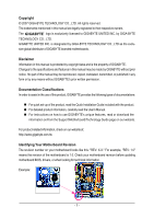
with the product. „ For detailed product information, carefully read the User's Manual. „ For instructions on how to use GIGABYTE's unique features, read or download the information on/from the Support\Motherboard\Technology Guide page on our website. For product-related information, check on our - Gigabyte GA-P35-DS3L | Manual - Page 4
...6 GA-P35-DS3L/S3L Motherboard Layout 7 Block Diagram ...8 Chapter 1 Hardware Installation 9 1-1 Installation Precautions 9 1-2 Product Specifications 10 1-3 Installing the CPU and CPU Cooler 13 1-3-1 Installing the CPU 13 1-3-2 Installing the CPU Cooler 15 1-4 Installing the Memory 16 - Gigabyte GA-P35-DS3L | Manual - Page 5
Unique Features 57 4-1 Xpress Recovery2 57 4-2 BIOS Update Utilities 62 4-2-1 Updating the BIOS with the Q-Flash Utility 62 4-2-2 Updating the BIOS with the @BIOS Utility 65 4-3 EasyTune 5 ...67 4-4 Windows Vista ReadyBoost 68 Chapter 5 Appendix ...69 5-1 Configuring Audio Input and Output 69 - Gigabyte GA-P35-DS3L | Manual - Page 6
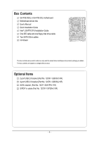
Box Contents GA-P35-DS3L or GA-P35-S3L motherboard Motherboard driver disk User's Manual Quick Installation Guide Intel® LGA775 CPU Installation Guide One IDE cable and one floppy disk drive cable Two SATA 3Gb/s cables I/O Shield The box contents above are for reference only and the actual items - Gigabyte GA-P35-DS3L | Manual - Page 7
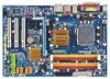
GA-P35-DS3L/S3L Motherboard Layout KB_MS COAXIAL OPTICAL ATX_12V LGA775 CPU_FAN ATX COM LPT DDRII1 GA-P35-DS3L/S3L R_USB SYS_FAN2 USB LAN F_AUDIO AUDIO SYS_FAN1 PCIE_3 RTL8111B PCIE_16 PCIE_1 SPDIF_O CODEC PCIE_2 SPDIF_I PCI1 PCI2 IT8718 PCI3 CD_IN Intel® P35 FDD DDRII3 DDRII4 - Gigabyte GA-P35-DS3L | Manual - Page 8
/33 IDE Channel JMicron 368 x1 PCI Express Bus RJ45 RTL 8111B x1 3 PCI Express x1 x 1 x1 x1 PCIe CLK (100 MHz) PCI Bus Host Interface DDR2 1066/800/667 MHz Intel® P35 Dual Channel Memory MCH CLK (333/266/200 MHz) Intel® ICH9 BIOS 4 SATA 3Gb/s 12 USB Ports CODEC IT8718 Floppy LPT Port - Gigabyte GA-P35-DS3L | Manual - Page 9
, carefully read the user's manual and follow these procedures: • Prior to installation, do not remove or break motherboard S/N (Serial Number) discharge (ESD) wrist strap when handling electronic components such as a motherboard, CPU or memory. If you do not have an ESD wrist strap, keep your hands - Gigabyte GA-P35-DS3L | Manual - Page 10
disk drive connector supporting up to 1 floppy disk drive Š Integrated in the South Bridge Š Up to 12 USB 2.0/1.1 ports (6 on the back panel, 6 via the USB brackets connected to the internal USB headers) "*" Only the GA-P35-DS3L adopts All-Solid Capacitor design. GA-P35-DS3L/S3L Motherboard - 10 - Gigabyte GA-P35-DS3L | Manual - Page 11
Š 1 x 24-pin ATX main power connector Š 1 x 4-pin ATX 12V power connector Š 1 x floppy disk drive connector Š 1 x IDE connector Š 4 x SATA 3Gb/s connectors Š 1 x CPU fan header Š 2 x system fan headers Š 1 x power fan header Š 1 x front panel header Š 1 x front panel audio header Š 1 x CD - Gigabyte GA-P35-DS3L | Manual - Page 12
Windows Vista (on ICH9, hot plug is supported in Windows Vista only) and configure the SATA connectors for AHCI mode. (Refer to Chapter 2, "BIOS Setup," "Integrated Peripherals," for details on enabling AHCI.) (Note 3) Available functions in Easytune may differ by motherboard model. GA-P35-DS3L/S3L - Gigabyte GA-P35-DS3L | Manual - Page 13
specifications including the CPU, graphics card, memory, hard drive, etc. Hyper-Threading Technology System Requirements: (Go to Intel's website for more information about the Hyper-Threading Technology) • An Intel® CPU that supports HT Technology • A chipset that supports HT Technology • An - Gigabyte GA-P35-DS3L | Manual - Page 14
one corner of the CPU socket (or you may align the CPU notches with the socket alignment keys) and gently insert the CPU into position. Step 5: Once the CPU is properly inserted, replace the load plate and push the CPU socket lever back into its locked position. GA-P35-DS3L/S3L Motherboard - 14 - - Gigabyte GA-P35-DS3L | Manual - Page 15
. Check that the Male and Female push pins are joined closely. (Refer to your CPU cooler installation manual for instructions on installing the cooler.) Step 5: After the installation, check the back of the motherboard. If the push pin is inserted as the picture above, the installation is complete - Gigabyte GA-P35-DS3L | Manual - Page 16
, a message which says memory is operating in Flex Memory Mode will appear during the POST. Intel® Flex Memory Technology offers greater flexibility to upgrade by allowing different memory sizes to be populated and remain in Dual Channel mode/performance. GA-P35-DS3L/S3L Motherboard - 16 - - Gigabyte GA-P35-DS3L | Manual - Page 17
computer and unplug the power cord from the power outlet to prevent damage to the memory module. DDR2 DIMMs are not compatible to DDR DIMMs. Be sure to install DDR2 DIMMs on this motherboard. Notch DDR2 DIMM A DDR2 memory module has a notch, so it can only fit in one direction. Follow the steps - Gigabyte GA-P35-DS3L | Manual - Page 18
the PCI Express x16 slot. Make sure the graphics card is locked by the latch at the end of the PCI Express x16 slot. • Removing the Card: Press the white latch at the end of the PCI Express x16 slot to release the card and then pull the card straight up from the slot. GA-P35-DS3L/S3L Motherboard - Gigabyte GA-P35-DS3L | Manual - Page 19
an optical digital audio in connector. Serial Port Use the serial port to connect devices such as a mouse, modem or other peripherals. USB Port The USB port supports the USB 2.0/1.1 specification. Use this port for USB devices such as an USB keyboard/mouse, USB printer, USB flash drive and etc - Gigabyte GA-P35-DS3L | Manual - Page 20
perform different functions via the audio software. Only microphones still MUST be connected to the default Mic in jack ( ). Refer to the instructions on setting up a 2/4/5.1/ 7.1-channel audio configuration in Chapter 5, "Configuring 2/4/5.1/7.1-Channel Audio." GA-P35-DS3L/S3L Motherboard - 20 - - Gigabyte GA-P35-DS3L | Manual - Page 21
Connectors 1 3 2 12 4 19 15 13 14 7 5 6 18 9 8 16 17 11 10 1) ATX_12V 2) ATX (Power Connector) 3) CPU_FAN 4) SYS_FAN1 5) SYS_FAN2 6) PWR_FAN 7) FDD 8) IDE1 9) SATAII0/1/4/5 10) F_PANEL 11) PWR_LED has been securely attached to the connector on the motherboard. - 21 - Hardware Installation - Gigabyte GA-P35-DS3L | Manual - Page 22
to the power connector in the correct orientation. The 12V power connector mainly supplies power to the CPU. If the 12V power connector is not connected, the computer will not start. • To meet 5V +5V +5V +5V (Only for 2x12-pinATX) GND (Only for 2x12-pin ATX) GA-P35-DS3L/S3L Motherboard - 22 - - Gigabyte GA-P35-DS3L | Manual - Page 23
wire. The motherboard supports CPU fan speed control, which requires the use of a CPU fan with fan Drive Connector) This connector is used to connect a floppy disk drive. The types of floppy disk drives supported are: 360 KB, 720 KB, 1.2 MB, 1.44 MB, and 2.88 MB. Before connecting a floppy disk drive - Gigabyte GA-P35-DS3L | Manual - Page 24
) The IDE connector supports up to two IDE devices such as hard drives and optical drives. Before attaching the supports a single SATA device. SATAII0 7 1 1 7 SATAII1 SATAII4 7 1 Pin No. 1 2 3 4 5 6 7 Definition GND TXP TXN GND RXN RXP GND 1 7 SATAII5 GA-P35-DS3L/S3L Motherboard - Gigabyte GA-P35-DS3L | Manual - Page 25
, the BIOS may issue beeps in different patterns to indicate the problem. Refer to Chapter 5, "Troubleshooting," for information about beep codes. • HD (IDE Hard Drive Activity LED, Blue) Connects to the hard drive activity LED on the chassis front panel. The LED is on when the hard drive is reading - Gigabyte GA-P35-DS3L | Manual - Page 26
. • Some chassis provide a front panel audio module that has separated connectors on each wire instead of a single plug. For information about connecting the front panel audio module that has different wire assignments, please contact the chassis manufacturer. GA-P35-DS3L/S3L Motherboard - 26 - - Gigabyte GA-P35-DS3L | Manual - Page 27
) You may connect the audio cable that came with your optical drive to the header. Pin No. Definition 1 CD-L 1 2 GND 3 GND 4 CD-R 14) SPDIF_I (S/PDIF In Header) This header supports digital S/PDIF in and can connect to an audio device that supports digital audio out via an optional - Gigabyte GA-P35-DS3L | Manual - Page 28
GND 8 GND 9 No Pin 10 NC • Do not plug the IEEE 1394 bracket (2x5-pin) cable into the USB header. • Prior to installing the USB bracket, be sure to turn off your computer and unplug the power cord from the power outlet to prevent damage to the USB bracket. GA-P35-DS3L/S3L Motherboard - 28 - - Gigabyte GA-P35-DS3L | Manual - Page 29
the jumper. Failure to do so may cause damage to the motherboard. • After system restart, go to BIOS Setup to load factory defaults (select Load Optimized Defaults) or manually configure the BIOS settings (refer to Chapter 2, "BIOS Setup," for BIOS configurations). - 29 - Hardware Installation - Gigabyte GA-P35-DS3L | Manual - Page 30
English 19) BATTERY The battery provides power to keep the values (such as BIOS configurations, date, and time information) in the CMOS when the computer is turned face up). • Used batteries must be handled in accordance with local environmental regulations. GA-P35-DS3L/S3L Motherboard - 30 - - Gigabyte GA-P35-DS3L | Manual - Page 31
the GIGABYTE Q-Flash or @BIOS utility. • Q-Flash allows the user to quickly and easily upgrade or back up BIOS without entering the operating system. • @BIOS is a Windows-based utility that searches and downloads the latest version of BIOS from the Internet and updates the BIOS. For instructions on - Gigabyte GA-P35-DS3L | Manual - Page 32
the device boot order will still be based on BIOS Setup settings. You can access Boot Menu again to change the first boot device setting as needed. : Q-Flash Press the key to access the Q-Flash utility directly without having to enter BIOS Setup first. GA-P35-DS3L/S3L Motherboard - 32 - Gigabyte GA-P35-DS3L | Manual - Page 33
> to accept or enter a sub-menu. (Sample BIOS Version: GA-P35-DS3L F3a) CMOS Setup Utility-Copyright (C) 1984-2007 Award Software ` Standard CMOS Features ` Advanced BIOS Features ` Integrated Peripherals ` Power Management Setup ` PnP/PCI Configurations ` PC Health Status ` MB Intelligent Tweaker - Gigabyte GA-P35-DS3L | Manual - Page 34
and exit BIOS Setup. (Pressing can also carry out this task.) „ Exit Without Saving Abandon all changes and the previous settings remain in effect. Pressing to the confirmation message will exit BIOS Setup. (Pressing can also carry out this task.) GA-P35-DS3L/S3L Motherboard - 34 - Gigabyte GA-P35-DS3L | Manual - Page 35
of the device during the POST for faster system startup. • Manual Allows you to manually enter the specifications of the hard drive when the hard drive access mode is set to CHS. Access Mode Sets the hard drive access mode. Options are: Auto (default), CHS, LBA, Large. - 35 - BIOS Setup - Gigabyte GA-P35-DS3L | Manual - Page 36
are determined by the BIOS POST. Base Memory Also called conventional memory. Typically, 640 KB will be reserved for the MS-DOS operating system. Extended Memory The amount of extended memory. Total Memory The total amount of memory installed on the system. GA-P35-DS3L/S3L Motherboard - 36 - - Gigabyte GA-P35-DS3L | Manual - Page 37
the hard drive and to issue warnings when a third party hardware monitor utility is installed. (Default: Disabled) (Note) This item is present only if you install a CPU that supports this feature. For more information about Intel CPUs' unique features, please visit Intel's website. - 37 - BIOS - Gigabyte GA-P35-DS3L | Manual - Page 38
as the first display. (Default) PEG Sets the PCI Express graphics card as the first display. (Note) This item is present only if you install a CPU that supports this feature. For more information about Intel CPUs' unique features, please visit Intel's website. GA-P35-DS3L/S3L Motherboard - 38 - - Gigabyte GA-P35-DS3L | Manual - Page 39
USB Controller USB 2.0 Controller USB Keyboard Support USB Mouse Support Legacy USB storage detect Azalia Codec Onboard H/W LAN ` SMART LAN Onboard LAN Boot ICH9 Southbridge) Configures the SATA controllers integrated in the Intel ICH9 storage driver to not support Native mode, e.g. Windows 9X/ME - Gigabyte GA-P35-DS3L | Manual - Page 40
Gigabit hub will only operate at a speed of 10/100Mbps in MS-DOS mode; it will operate at a normal speed of 10/100/1000Mbps in Windows mode or when the LAN Boot ROM is activated. GA-P35-DS3L/S3L Motherboard - 40 - - Gigabyte GA-P35-DS3L | Manual - Page 41
English When a Cable Problem Occurs... If a cable problem occurs on a approximate length of the attached LAN cable. Onboard LAN Boot ROM Allows you to decide whether to activate the boot ROM integrated with the onboard LAN chip. (Default: Extended Capabilities Port), ECP+EPP. - 41 - BIOS Setup - Gigabyte GA-P35-DS3L | Manual - Page 42
S3(STR) Enables the system to enter the ACPI S3 (Suspend to RAM) sleep state (default). In S3 PCI or PCIe device. Note: To use this function, you need an ATX supports wake-up function. (Default: Enabled) (Note) Supported on Windows® Vista® operating system only. GA-P35-DS3L/S3L Motherboard - 42 - - Gigabyte GA-P35-DS3L | Manual - Page 43
effective. HPET Support (Note) Enables or disables High Precision Event Timer (HPET) for Windows® Vista® PS/2 keyboard wake-up event. Note: you need an ATX power supply providing at least 1A on the 5VSB lead. of the AC power. (Default) Full-On Memory The system is turned on upon the return - Gigabyte GA-P35-DS3L | Manual - Page 44
12,14,15 to the first PCI slot. BIOS auto-assigns IRQ to the second PCI slot. (Default) Assigns IRQ 3,4,5,7,9,10,11,12,14,15 to the second PCI slot. BIOS auto-assigns IRQ to the third PCI slot. (Default) Assigns IRQ 3,4,5,7,9,10,11,12,14,15 to the third PCI slot. GA-P35-DS3L/S3L Motherboard - 44 - - Gigabyte GA-P35-DS3L | Manual - Page 45
of previous chassis intrusion status and the Case Opened field will show "No" at next boot. (Default: Disabled) Case Opened Displays the detection status of the chassis intrusion detection device attached to the motherboard CI header. If the system chassis cover is removed, this field will show "Yes - Gigabyte GA-P35-DS3L | Manual - Page 46
Sets PWM mode for a 4-pin CPU fan. Note: The Voltage mode can be set for a 3-pin CPU fan or a 4-pin CPU fan. However, for a 4-pin CPU fan that is not designed following Intel PWM fan specifications, selecting PWM mode may not effectively reduce the fan speed. GA-P35-DS3L/S3L Motherboard - 46 - - Gigabyte GA-P35-DS3L | Manual - Page 47
: If your system fails to boot after overclocking, please wait for 20 seconds to allow for automated system reboot, or clear the CMOS values to reset the board to default values. (Default: Disabled) (Note) This item appears only if you install a CPU that supports this feature. - 47 - BIOS Setup - Gigabyte GA-P35-DS3L | Manual - Page 48
two different memory timing configurations. If your system becomes unstable after you overclock the DDR2 memory, select Option 1 or Option 2 to help make your system more stable. Option 1 Option 2 Memory Timing Configuration 1. (Default) Memory Timing Configuration 2. GA-P35-DS3L/S3L Motherboard - Gigabyte GA-P35-DS3L | Manual - Page 49
the system voltages. Auto lets BIOS automatically set the system voltages as required. Manual allows all voltage control items below to be configurable. (Default: Manual) DDR2 OverVoltage Control Allows you to set memory voltage. Normal Supplies the memory voltage as required. (Default) +0.1V - Gigabyte GA-P35-DS3L | Manual - Page 50
Press on this item and then press the key to load the optimal BIOS default settings. The BIOS defaults settings helps the system to operate in optimum state. Always load the Optimized defaults after updating the BIOS or after clearing the CMOS values. GA-P35-DS3L/S3L Motherboard - 50 - - Gigabyte GA-P35-DS3L | Manual - Page 51
, you must enter the supervisor password (or user password) at system startup to continue system boot. In BIOS Setup, you must enter the supervisor password if you wish to make changes to BIOS settings. The user password only allows you to view the BIOS settings but not to make changes. To clear - Gigabyte GA-P35-DS3L | Manual - Page 52
` PnP/PCI Configurations Save BIOS F12: Load CMOS from BIOS Abandon all Data Press on this item and press the key. This exits the BIOS Setup without saving the changes made in BIOS Setup to the CMOS. Press or to return to the BIOS Setup Main Menu. GA-P35-DS3L/S3L Motherboard - Gigabyte GA-P35-DS3L | Manual - Page 53
other drivers. • After the drivers are installed, follow the onscreen instructions to restart your system. You can install other applications included in the motherboard driver disk. • For USB 2.0 driver support under the Windows XP operating system, please install the Windows XP Service Pack - Gigabyte GA-P35-DS3L | Manual - Page 54
all the tools and applications that GIGABYTE develops and some free software. You may press the Install button following an item to install it. 3-3 Driver CD Information This page provides information about the drivers, applications and tools in this driver disk. GA-P35-DS3L/S3L Motherboard - 54 - - Gigabyte GA-P35-DS3L | Manual - Page 55
English 3-4 Hardware Information This page provides information about the hardware devices on this motherboard. 3-5 Contact Us Check the contacts information of the GIGABYTE headquarter in Taiwan and the overseas branch offices on the last page of this manual. - 55 - Drivers Installation - Gigabyte GA-P35-DS3L | Manual - Page 56
English GA-P35-DS3L/S3L Motherboard - 56 - - Gigabyte GA-P35-DS3L | Manual - Page 57
® 2000 with SP3 or later; Windows® XP with SP1 or later • Xpress Recovery and Xpress Recovery2 are different utilities. For example, a backup file created with Xpress Recovery cannot be restored using Xpress Recovery2. • USB hard drives are not supported. • Hard drives in RAID/AHCI mode are not - Gigabyte GA-P35-DS3L | Manual - Page 58
Windows XP and Partitioning the Hard Drive 1. Set CD-ROM drive as the first boot device under "Advanced BIOS Features" in the BIOS Setup program. Save the changes and exit. 2. When partitioning your hard drive of the operating system (Figure 3). Figure 3 GA-P35-DS3L/S3L Motherboard - 58 - - Gigabyte GA-P35-DS3L | Manual - Page 59
you will not be able to create new partitions or use Xpress Recovery2. If this occurs, reinstall the operating system and re-partition your hard drive. Figure 6 In the New Partition Wizard, you MUST select Primary partition. This will reserve unallocated space for Xpress Recovery2 to use. Figure - Gigabyte GA-P35-DS3L | Manual - Page 60
this hard drive contains the Windows operating system. When the Windows operating system is detected, Xpress Recovery2 will begin the backup process (Figure 11). Figure 10 Figure 11 3. When finished, go to Disk Management to check disk allocation. Figure 12 GA-P35-DS3L/S3L Motherboard Xpress - Gigabyte GA-P35-DS3L | Manual - Page 61
the backup file, select REMOVE (Figure 15). 2. After the backup file is removed, no backup image file will be present in Disk Management and hard drive space will be freed up (Figure 16). Figure 15 F. Exiting Xpress Recovery2 Select REBOOT to exit Xpress Recovery2. Figure 16 Figure 17 - 61 - Gigabyte GA-P35-DS3L | Manual - Page 62
You Begin: 1. From GIGABYTE's website, download the latest compressed BIOS update file that matches your motherboard model. 2. Extract the file and save the new BIOS file (e.g. p35ds3l.f1) to your floppy disk, USB flash drive, or hard drive. Note: The USB flash drive or hard drive must use FAT32/16 - Gigabyte GA-P35-DS3L | Manual - Page 63
select Update BIOS from Drive and press . • The Save Main BIOS to Drive option allows you to save the current BIOS file. • Q-Flash only supports USB flash drive or hard drives using FAT32/16/12 file system. • If the BIOS update file is saved to a hard drive in RAID/AHCI mode or a hard drive - Gigabyte GA-P35-DS3L | Manual - Page 64
F11: Save CMOS to BIOS F12: Load CMOS from BIOS Load Optimized Defaults Press to load BIOS defaults Step 6: Select Save & Exit Setup and then press to save settings to CMOS and exit BIOS Setup. The procedure is complete after the system restarts. GA-P35-DS3L/S3L Motherboard - 64 - - Gigabyte GA-P35-DS3L | Manual - Page 65
and Using @BIOS: Use the motherboard driver disk included with the motherboard to install @BIOS. • Installing the @BIOS utility. • Accessing the @BIOS utility. Select @BIOS and click Install. Click Start>Programs>GIGABYTE>@BIOS C. Options and Instructions: 1. Save the Current BIOS File In the - Gigabyte GA-P35-DS3L | Manual - Page 66
matches your motherboard model. Updating the BIOS with an incorrect BIOS file could result in an unbootable system. Step 4: As the system boots, press to enter the BIOS Setup program. Select Load Optimized Defaults and press to load BIOS defaults. GA-P35-DS3L/S3L Motherboard - 66 - Gigabyte GA-P35-DS3L | Manual - Page 67
the BIOS Setup program. EasyTuneTM 5 provides the following functions (Note 1): overclocking/overvoltage, C.I.A./ M.I.B. (Note 2), smart fan control, and hardware monitoring and warning. (For instructions on using EasyTune5, read or download the information on/from the Support\Motherboard\Utility - Gigabyte GA-P35-DS3L | Manual - Page 68
slider or spin box. Click Apply and then OK to turn on ReadyBoost. • The USB flash drive must have at least 256 MB of space. • The recommended amount of memory to use for ReadyBoost acceleration is one to three times the amount of RAM installed in your computer. GA-P35-DS3L/S3L Motherboard - 68 - - Gigabyte GA-P35-DS3L | Manual - Page 69
in or Line in jack and manually configure the jack for microphone functionality. • If your front panel audio supports Intel HD Audio standard, you can have both the front and back panel audio connectors active simultaneously. High Definition Audio (HD Audio) HD Audio includes multiple high quality - Gigabyte GA-P35-DS3L | Manual - Page 70
Panel. Before installing the audio driver, make sure the "Microsoft UAA Bus driver for High Definition Audio" has been installed from the motherboard driver disk and your operating system has been updated with the latest Service Pack for Windows. Step 2: Click the Audio I/O tab. In the speaker list - Gigabyte GA-P35-DS3L | Manual - Page 71
Global Connector Settings box, select the Disable front panel jack detection check box. Click OK to activiate the AC'97 functionality. When using an AC'97 front panel audio module, you can only have audio signals present on either the front or the back panel audio connections, but not both at the - Gigabyte GA-P35-DS3L | Manual - Page 72
audio signals to the computer for audio processing. A. Installing the S/PDIF In Cable: Step 1: First, attach the connector at the end of the cable to the SPDIF_I header on your motherboard. Step 2: Secure the metal bracket to the chassis back panel with a screw. GA-P35-DS3L/S3L Motherboard - Gigabyte GA-P35-DS3L | Manual - Page 73
a S/PDIF out Cable Connect a S/PDIF coaxial cable or a S/PDIF optical cable (either one) to an external decoder for transmitting the S/PDIF digital audio signals. S/PDIF Coaxial Cable S/PDIF Optical Cable C. Configuring S/PDIF out: Click the tool icon in the DIGITAL section. In the S/PDIF In/Out - Gigabyte GA-P35-DS3L | Manual - Page 74
the front panel. Then configure the jack for microphone functionality. Note: The microphone functions on the front panel and back panel cannot be used at the same time. Step 3: Locate the Volume icon in your system tray and click it to open the volume control panel GA-P35-DS3L/S3L Motherboard - 74 - Gigabyte GA-P35-DS3L | Manual - Page 75
using the microphone function on or the front panel, do not select the Mute check box under Front Pink In or Front Green In in Master Volume. It , go to Options and click Properties. In the Mixer device list, select Realtek HD Audio Input. Then set the recording sound level properly. Do NOT mute - Gigabyte GA-P35-DS3L | Manual - Page 76
the Advanced button under a volume control option (e.g. Front Green In, Front Pink In). In the Other Controls field, select Sound Recorder Recording the Sound: 1. Make sure you have connected the audio input device (e.g. microphone) to the computer. 2. On the File GA-P35-DS3L/S3L Motherboard - 76 - - Gigabyte GA-P35-DS3L | Manual - Page 77
English 5-2 Troubleshooting 5-2-1 Frequently Asked Questions To read more FAQs for your motherboard, please go to the Support\Motherboard\FAQ page on GIGABYTE's website. Q: In the BIOS Setup program, why are some BIOS options missing? A: Some advanced options are hidden in the BIOS Setup program. - Gigabyte GA-P35-DS3L | Manual - Page 78
insert the memory into the memory socket. The problem is verified and solved. Press to enter BIOS Setup. Select "Load Fail-Safe Defaults" (or "Load Optimized Defaults"). Select "Save & Exit Setup" to save changes and exit BIOS Setup. A (Continued...) GA-P35-DS3L/S3L Motherboard - 78 - Gigabyte GA-P35-DS3L | Manual - Page 79
is verified and solved. END If the procedure above is unable to solve your problem, contact the place of purchase or local dealer for help. Or go to the Support\Technical Service Zone page to submit your question. Our customer service staff will reply you as soon as possible. - 79 - Appendix - Gigabyte GA-P35-DS3L | Manual - Page 80
English GA-P35-DS3L/S3L Motherboard - 80 - - Gigabyte GA-P35-DS3L | Manual - Page 81
- 81 - Appendix English - Gigabyte GA-P35-DS3L | Manual - Page 82
TEL: +86-24-83992901 FAX: +86-24-83992909 India GIGABYTE TECHNOLOGY (INDIA) LIMITED WEB address : http://www.giga-byte.co.in/ Saudi Arabia WEB address : http://www.gigabyte.com.sa Australia GIGABYTE TECHNOLOGY PTY. LTD. WEB address : http://www.gigabyte.com.au GA-P35-DS3L/S3L Motherboard - 82 - - Gigabyte GA-P35-DS3L | Manual - Page 83
Technology Co., Ltd. in SERBIA & MONTENEGRO WEB address : http://www.gigabyte.co.yu You may go to the GIGABYTE website, select your language in the language list on the top right corner of the website. GIGABYTE Global Service System To submit a technical or non-technical (Sales/ Marketing) question - Gigabyte GA-P35-DS3L | Manual - Page 84
- 84 -
-
 1
1 -
 2
2 -
 3
3 -
 4
4 -
 5
5 -
 6
6 -
 7
7 -
8
-
9
-
10
-
11
-
12
-
13
-
14
-
15
-
16
-
17
-
18
-
19
-
20
-
21
-
22
-
23
-
24
-
25
-
26
-
27
-
28
-
29
-
30
-
31
-
32
-
33
-
34
-
35
-
36
-
37
-
38
-
39
-
40
-
41
-
42
-
43
-
44
-
45
-
46
-
47
-
48
-
49
-
50
-
51
-
52
-
53
-
54
-
55
-
56
-
57
-
58
-
59
-
60
-
61
-
62
-
63
-
64
-
65
-
66
-
67
-
68
-
69
-
70
-
71
-
72
-
73
-
74
-
75
-
76
-
77
-
78
-
79
-
80
-
81
-
82
-
83
-
84
 |
 |

GA-P35-DS3L/
GA-P35-S3L
LGA775 socket motherboard for Intel
®
Core
TM
processor family/
Intel
®
Pentium
®
processor family/Intel
®
Celeron
®
processor family
User's Manual
Rev. 2001
12ME-P35DS3L-2001R
*
The WEEE marking on the product indicates this product must not be disposed of with user's other household waste
and must be handed over to a designated collection point for the recycling of waste electrical and electronic equipment!!
*
The WEEE marking applies only in European Union's member states.