Gigabyte GA-P35-DS3R Manual
Gigabyte GA-P35-DS3R Manual
 |
UPC - 818313003379
View all Gigabyte GA-P35-DS3R manuals
Add to My Manuals
Save this manual to your list of manuals |
Gigabyte GA-P35-DS3R manual content summary:
- Gigabyte GA-P35-DS3R | Manual - Page 1
GA-P35-DS3R/ GA-P35-DS3/ GA-P35-S3 LGA775 socket motherboard for Intel® CoreTM processor family/ Intel® Pentium® processor family/Intel® Celeron® processor family User's Manual Rev. 2002 12ME-P35DS3R-2002R - Gigabyte GA-P35-DS3R | Manual - Page 2
Motherboard GA-P35-DS3R/GA-P35-DS3/GA-P35-S3 Jul. 25, 2007 Motherboard GA-P35-DS3R/GA-P35-DS3/ GA-P35-S3 Jul. 25, 2007 - Gigabyte GA-P35-DS3R | Manual - Page 3
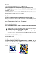
with the product. „ For detailed product information, carefully read the User's Manual. „ For instructions on how to use GIGABYTE's unique features, read or download the information on/from the Support\Motherboard\Technology Guide page on our website. For product-related information, check on our - Gigabyte GA-P35-DS3R | Manual - Page 4
...6 GA-P35-DS3R/DS3/S3 Motherboard Layout 7 Block Diagram ...8 Chapter 1 Hardware Installation 9 1-1 Installation Precautions 9 1-2 Product Specifications 10 1-3 Installing the CPU and CPU Cooler 13 1-3-1 Installing the CPU 13 1-3-2 Installing the CPU Cooler 15 1-4 Installing the Memory 16 - Gigabyte GA-P35-DS3R | Manual - Page 5
with the @BIOS Utility 71 4-3 EasyTune 5 ...73 4-4 Windows Vista ReadyBoost 74 Chapter 5 Appendix ...75 5-1 Configuring SATA Hard Drive(s 75 5-1-1 Configuring Intel® ICH9R SATA Controllers 75 5-1-2 Configuring GIGABYTE SATA2 SATA Controller 81 5-1-3 Making a SATA RAID/AHCI Driver Diskette 87 - Gigabyte GA-P35-DS3R | Manual - Page 6
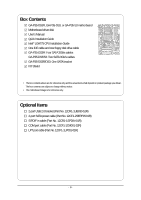
GA-P35-DS3R, GA-P35-DS3, or GA-P35-S3 motherboard Motherboard driver disk User's Manual Quick Installation Guide Intel® LGA775 CPU Installation Guide One IDE cable and one floppy disk drive cable GA-P35-DS3R: Four SATA 3Gb/s cables GA-P35-DS3/S3: Two SATA 3Gb/s cables GA-P35-DS3R/DS3: One SATA - Gigabyte GA-P35-DS3R | Manual - Page 7
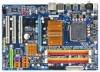
BATTERY Intel® ICH9R Intel® ICH9 CLR_CMOS SATAII2 SATAII3 GSATAII0 GIGABYTE SATA2 BIOS GSATAII1 IDE1 SATAII0 SATAII1 SATAII4 SATAII5 F_USB2 F_USB1 CI F_PANEL LPT PWR_LED SYS_FAN2 Only for GA-P35-DS3R. Only for GA-P35-DS3. Only for GA-P35-S3. "*" Only the GA-P35-DS3R/DS3 adopt - Gigabyte GA-P35-DS3R | Manual - Page 8
GIGABYTE SATA2 LAN RJ45 RTL 8111B x1 PCI Express Bus x1 3 PCI Express x1 x 1 x 1 x 1 PCIe CLK (100 MHz) PCI Bus Intel® P35 Intel® ICH9R Intel® ICH9 CODEC Dual Channel Memory MCH CLK (400(O.C.)/333/266/200 MHz) BIOS 6 SATA 3Gb/s 4 SATA 3Gb/s 12 USB Ports IT8718 Floppy LPT Port COM Port - Gigabyte GA-P35-DS3R | Manual - Page 9
's manual and follow these procedures: • Prior to installation, do not remove or break motherboard S/N wrist strap when handling electronic components such as a motherboard, CPU or memory. If you do not have an ESD wrist steps or have a problem related to the use of the product, please consult - Gigabyte GA-P35-DS3R | Manual - Page 10
- Support for SATA RAID 0, RAID 1, and JBOD Š iTE IT8718 chip: - 1 x floppy disk drive connector supporting up to 1 floppy disk drive Only for GA-P35-DS3R. Only for GA-P35-DS3. Only for GA-P35-S3. "*" Only the GA-P35-DS3R/DS3 adopt All-Solid Capacitor design. GA-P35-DS3R/DS3/S3 Motherboard - 10 - Gigabyte GA-P35-DS3R | Manual - Page 11
Hardware Monitor Š System voltage detection Š CPU/System temperature detection Š CPU/System/Power fan speed detection Š CPU overheating warning Š CPU/System/Power fan fail warning Š CPU fan speed control (Note 3) Only for GA-P35-DS3R. Only for GA-P35-DS3. Only for GA-P35-S3. - 11 - Hardware - Gigabyte GA-P35-DS3R | Manual - Page 12
CPU fan speed control function is supported will depend on the CPU cooler you install. (Note 4) Available functions in Easytune may differ by motherboard model. (Note 5) Due to chipset limitation, Intel ICH9R RAID driver does not support Windows 2000 operating system. GA-P35-DS3R/DS3/S3 Motherboard - Gigabyte GA-P35-DS3R | Manual - Page 13
enabled (Refer to Chapter 2, "BIOS Setup," "Advanced BIOS Features," for instructions on enabling the HT Technology.) 1-3-1 Installing the CPU A. Locate the alignment keys on the motherboard CPU socket and the notches on the CPU. LGA775 CPU Socket Alignment Key LGA 775 CPU Alignment Key Pin One - Gigabyte GA-P35-DS3R | Manual - Page 14
corner of the CPU socket (or you may align the CPU notches with the socket alignment keys) and gently insert the CPU into position. Step 5: Once the CPU is properly inserted, replace the load plate and push the CPU socket lever back into its locked position. GA-P35-DS3R/DS3/S3 Motherboard - 14 - - Gigabyte GA-P35-DS3R | Manual - Page 15
. Check that the Male and Female push pins are joined closely. (Refer to your CPU cooler installation manual for instructions on installing the cooler.) Step 5: After the installation, check the back of the motherboard. If the push pin is inserted as the picture above, the installation is complete - Gigabyte GA-P35-DS3R | Manual - Page 16
, a message which says memory is operating in Flex Memory Mode will appear during the POST. Intel® Flex Memory Technology offers greater flexibility to upgrade by allowing different memory sizes to be populated and remain in Dual Channel mode/performance. GA-P35-DS3R/DS3/S3 Motherboard - 16 - - Gigabyte GA-P35-DS3R | Manual - Page 17
computer and unplug the power cord from the power outlet to prevent damage to the memory module. DDR2 DIMMs are not compatible to DDR DIMMs. Be sure to install DDR2 DIMMs on this motherboard. Notch DDR2 DIMM A DDR2 memory module has a notch, so it can only fit in one direction. Follow the steps - Gigabyte GA-P35-DS3R | Manual - Page 18
sure the motherboard supports the expansion card. Carefully read the manual that came with replace the chassis cover(s). 6. Turn on your computer. If necessary, go to BIOS Setup to make any required BIOS changes for your expansion card(s). 7. Install the driver GA-P35-DS3R/DS3/S3 Motherboard - 18 - - Gigabyte GA-P35-DS3R | Manual - Page 19
and SATA power cable to your SATA device. For SATA device in external enclosure, you only need to connect the SATA signal cable. Before connecting the SATA signal cable, make sure to turn off the power of the external enclosure. "*" The SATA bracket is included with the GA-P35-DS3R/DS3 only - Gigabyte GA-P35-DS3R | Manual - Page 20
system provides an optical digital audio in connector. USB Port The USB port supports the USB 2.0/1.1 specification. Use this port for USB devices such as an USB keyboard/mouse, USB printer, USB flash drive and etc. RJ-45 LAN Port The Gigabit Ethernet LAN port provides Internet connection at up - Gigabyte GA-P35-DS3R | Manual - Page 21
to perform different functions via the audio software. Only microphones still MUST be connected to the default Mic in jack ( ). Refer to the instructions on setting up a 2/4/5.1/ 7.1-channel audio configuration in Chapter 5, "Configuring 2/4/5.1/7.1-Channel Audio." - 21 - Hardware Installation - Gigabyte GA-P35-DS3R | Manual - Page 22
devices. • After installing the device and before turning on the computer, make sure the device cable has been securely attached to the connector on the motherboard. Only for GA-P35-DS3R. GA-P35-DS3R/DS3/S3 Motherboard - 22 - - Gigabyte GA-P35-DS3R | Manual - Page 23
supply can supply enough stable power to all the components on the motherboard. Before connecting the power connector, first make sure the power supply the correct orientation. The 12V power connector mainly supplies power to the CPU. If the 12V power connector is not connected, the computer will - Gigabyte GA-P35-DS3R | Manual - Page 24
drives supported are: 360 KB, 720 KB, 1.2 MB, 1.44 MB, and 2.88 MB. Before connecting a floppy disk drive, be sure to locate pin 1 of the connector and the floppy disk drive cable. The pin 1 of the cable is typically designated by a stripe of different color. 34 33 GA-P35-DS3R/DS3/S3 Motherboard - Gigabyte GA-P35-DS3R | Manual - Page 25
/s standard and are compatible with SATA 1.5Gb/s standard. Each SATA connector supports a single SATA device. The ICH9R controller supports RAID 0, RAID 1, RAID 5 and RAID 10. Refer to Chapter 5, "Configuring SATA Hard Drive(s)," for instructions on configuring a RAID array. Pin No. Definition - Gigabyte GA-P35-DS3R | Manual - Page 26
end of the SATA 3Gb/s cable to your SATA hard drive. A RAID 0 or RAID 1 configuration requires at least two hard drives. If more than two hard drives are to be used, the total number of hard drives must be an even number. Only for GA-P35-DS3. Only for GA-P35-S3. GA-P35-DS3R/DS3/S3 Motherboard - 26 - Gigabyte GA-P35-DS3R | Manual - Page 27
1 MPD+ 2 MPD- 1 3 MPD- System Status LED S0 On S1 Blinking S3/S4/S5 Off 12) BATTERY The battery provides power to keep the values (such as BIOS configurations, date, and time information) in the CMOS when the computer is turned off. Replace the battery when the battery voltage drops to - Gigabyte GA-P35-DS3R | Manual - Page 28
front panel module mainly consists of power switch, reset switch, power LED, hard drive activity LED, speaker and etc. When connecting your chassis front panel module to this header, make sure the wire assignments and the pin assignments are matched correctly. GA-P35-DS3R/DS3/S3 Motherboard - 28 - - Gigabyte GA-P35-DS3R | Manual - Page 29
Header) The front panel audio header supports Intel High Definition audio (HD) and AC'97 audio. You may connect your chassis front panel audio module to this header. Make sure the wire assignments of the module connector match the pin assignments of the motherboard header. Incorrect connection - Gigabyte GA-P35-DS3R | Manual - Page 30
display to the graphics card and have digital audio output from the HDMI display at the same time. For information about connecting the S/PDIF digital audio cable, carefully read the manual for your expansion card. 1 Pin No. Definition 1 SPDIFO 2 GND GA-P35-DS3R/DS3/S3 Motherboard - 30 - - Gigabyte GA-P35-DS3R | Manual - Page 31
headers conform to USB 2.0/1.1 specification. Each USB header can provide two USB ports via an optional USB bracket. For purchasing the optional USB bracket, please contact the local dealer. Pin No. Definition 9 1 10 2 1 Power (5V) 2 Power (5V) 3 USB DX- 4 USB DY- 5 USB DX+ 6 USB DY - Gigabyte GA-P35-DS3R | Manual - Page 32
information and BIOS configurations) and reset the CMOS motherboard. • After system restart, go to BIOS Setup to load factory defaults (select Load Optimized Defaults) or manually configure the BIOS settings (refer to Chapter 2, "BIOS Setup," for BIOS configurations). GA-P35-DS3R/DS3/S3 Motherboard - Gigabyte GA-P35-DS3R | Manual - Page 33
English 22) CI (Chassis Intrusion Header) This motherboard provides a chassis detection feature that detects if the chassis cover has been removed. This function requires a chassis with chassis intrusion detection design. Pin No. Definition 1 1 Signal 2 GND - 33 - Hardware Installation - Gigabyte GA-P35-DS3R | Manual - Page 34
English GA-P35-DS3R/DS3/S3 Motherboard - 34 - - Gigabyte GA-P35-DS3R | Manual - Page 35
Windows-based utility that searches and downloads the latest version of BIOS from the Internet and updates the BIOS. For instructions on using the Q-Flash and @BIOS utilities, refer to Chapter 4, "BIOS Update Utilities." • Because BIOS flashing is potentially risky, if you do not encounter problems - Gigabyte GA-P35-DS3R | Manual - Page 36
device boot order will still be based on BIOS Setup settings. You can access Boot Menu again to change the first boot device setting as needed. : Q-Flash Press the key to access the Q-Flash utility directly without having to enter BIOS Setup first. GA-P35-DS3R/DS3/S3 Motherboard - 36 - Gigabyte GA-P35-DS3R | Manual - Page 37
among the items and press to accept or enter a sub-menu. (Sample BIOS Version: GA-P35-DS3R F5c) CMOS Setup Utility-Copyright (C) 1984-2007 Award Software ` Standard CMOS Features ` Advanced BIOS Features ` Integrated Peripherals ` Power Management Setup ` PnP/PCI Configurations ` PC Health - Gigabyte GA-P35-DS3R | Manual - Page 38
boot, etc. „ Advanced BIOS Features Use this menu to configure the device boot order, advanced features available on the CPU, and the primary display adapter. „ Integrated Peripherals Use this menu to configure all peripheral devices, such as IDE, SATA, USB, integrated audio, and integrated LAN - Gigabyte GA-P35-DS3R | Manual - Page 39
A Floppy 3 Mode Support [1.44M, 3.5"] [Disabled] Halt On [All, But Keyboard] Base Memory Extended Memory Total Memory KLJI: Move Enter: SATA device on this channel. Extended IDE Drive Configure your IDE/SATA devices by using one of the two methods below: Only for GA-P35-DS3R. - 39 - BIOS - Gigabyte GA-P35-DS3R | Manual - Page 40
manually Mode Support Allows BIOS POST. Base Memory Also called conventional memory. Typically, 640 KB will be reserved for the MS-DOS operating system. Extended Memory The amount of extended memory. Total Memory The total amount of memory installed on the system. GA-P35-DS3R/DS3/S3 Motherboard - Gigabyte GA-P35-DS3R | Manual - Page 41
to accept. Options are: Floppy, LS120, Hard Disk, CDROM, ZIP, USB-FDD, USB-ZIP, USB-CDROM, USB-HDD, Legacy LAN, Disabled. Password Check Specifies whether a password is required every time the system boots, or only when you enter BIOS Setup. After configuring this item, set the password(s) under - Gigabyte GA-P35-DS3R | Manual - Page 42
Windows NT4.0. (Default: Disabled) No-Execute Memory Protect (Note) Enables or disables Intel whether to display the GIGABYTE Logo at system startup. CPU that supports this feature. For more information about Intel CPUs' unique features, please visit Intel's website. GA-P35-DS3R/DS3/S3 Motherboard - Gigabyte GA-P35-DS3R | Manual - Page 43
SATA controllers to AHCI mode. Advanced Host Controller Interface (AHCI) is an interface specification that allows the storage driver to enable advanced Serial ATA features such as Native Command Queuing and hot plug. Only for GA-P35-DS3R. Only for GA-P35-DS3. Only for GA-P35-S3. (Note) Supported - Gigabyte GA-P35-DS3R | Manual - Page 44
Onboard H/W LAN Enables or disables the onboard LAN function. (Default: Enabled) If you wish to install a 3rd party add-in network card instead of using the onboard LAN, set this item to Disabled. Only for GA-P35-DS3R. Only for GA-P35-DS3. Only for GA-P35-S3. GA-P35-DS3R/DS3/S3 Motherboard - 44 - Gigabyte GA-P35-DS3R | Manual - Page 45
information for diagnosing your LAN cable: When No LAN Cable Is Attached... If no LAN cable is attached to the motherboard, the Status fields speed of 10/100/1000Mbps in Windows mode or when the LAN Boot ROM is activated. When a Cable Problem Occurs... If a cable problem occurs on a specified pair - Gigabyte GA-P35-DS3R | Manual - Page 46
378/IRQ7 (default), 278/IRQ5, 3BC/IRQ7, Disabled. Parallel Port Mode Selects an operating mode for the onboard parallel (LPT) port. Options are: SPP (Standard Parallel Port)(default), EPP (Enhanced Parallel Port), ECP (Extended Capabilities Port), ECP+EPP. GA-P35-DS3R/DS3/S3 Motherboard - 46 - - Gigabyte GA-P35-DS3R | Manual - Page 47
S3 (Suspend to RAM) sleep state ( Wake Up Allows the system to be awakened from an ACPI sleep state by a wake-up signal from a PCI or PCIe wake-up signal from a modem that supports wake-up function. (Default: Enabled) (Note) Supported on Windows® Vista® operating system only. - 47 - BIOS - Gigabyte GA-P35-DS3R | Manual - Page 48
the return of the AC power. (Default ) Full-On The system is turned on upon the return of the AC power. Memory The system returns to its last known awake state upon the return of the AC power. (Note) Supported on Windows® Vista® operating system only. GA-P35-DS3R/DS3/S3 Motherboard - 48 - - Gigabyte GA-P35-DS3R | Manual - Page 49
IRQ Assignment Auto 3,4,5,7,9,10,11,12,14,15 +/-/PU/PD: Value F10: Save F6: Fail-Safe Defaults ESC: Exit F1: General Help F7: Optimized Defaults BIOS auto-assigns IRQ to the first PCI slot. (Default) Assigns IRQ 3,4,5,7,9,10,11,12,14,15 to the first PCI slot - Gigabyte GA-P35-DS3R | Manual - Page 50
Help F7: Optimized Defaults Reset Case Open Status Keeps CPU/SYSTEM/POWER FAN Fail Warning Allows the system to emit warning sound if the CPU/system/power fan is not connected or fails. Check the fan condition or fan connection when this occurs. (Default: Disabled) GA-P35-DS3R/DS3/S3 Motherboard - Gigabyte GA-P35-DS3R | Manual - Page 51
to control CPU fan speed. Auto Lets BIOS control CPU fan speed. (Default) Intel(R) QST Allows CPU fan speed to be controlled by the Intel Quiet System Technology (QST). This feature requires the installation of Intel Host Embedded Control Interface (HECI) driver from the motherboard driver disk - Gigabyte GA-P35-DS3R | Manual - Page 52
fails to boot after overclocking, please wait for 20 seconds to allow for automated system reboot, or clear the CMOS values to reset the board to default values. (Default: Disabled) (Note) This item appears only if you install a CPU that supports this feature. GA-P35-DS3R/DS3/S3 Motherboard - 52 - Gigabyte GA-P35-DS3R | Manual - Page 53
is automatically adjusted according to the CPU Host Frequency (Mhz) and System Memory Multiplier settings. High Speed DRAM DLL Settings Provides two different memory timing configurations. If your system becomes unstable after you overclock the DDR2 memory, select Option 1 or Option 2 to help - Gigabyte GA-P35-DS3R | Manual - Page 54
required. The adjustable range is dependent on the CPU being installed. (Default: Normal) Note: Increasing CPU voltage may result in damage to your CPU or reduce the useful life of the CPU. Normal CPU Vcore Displays the normal operating voltage of your CPU. GA-P35-DS3R/DS3/S3 Motherboard - 54 - - Gigabyte GA-P35-DS3R | Manual - Page 55
stable BIOS settings for the motherboard. BIOS Load Optimized Defaults Press on this item and then press the key to load the optimal BIOS default settings. The BIOS defaults settings helps the system to operate in optimum state. Always load the Optimized defaults after updating the BIOS - Gigabyte GA-P35-DS3R | Manual - Page 56
you to view the BIOS settings but not to make changes. To clear the password, press on the password item and when requested for the password, press again. The message "PASSWORD DISABLED" will appear, indicating the password has been cancelled. GA-P35-DS3R/DS3/S3 Motherboard - 56 - - Gigabyte GA-P35-DS3R | Manual - Page 57
Status Exit Without Saving ` MB Intelligent Tweaker(M.I.T.) ESC: Quit F8: Q-Flash KLJI: Select Item F10: Save & Exit Setup F11: Save CMOS to BIOS F12: Load CMOS from BIOS Save Data to CMOS Press on this item and press the key. This saves the changes to the CMOS and exits the - Gigabyte GA-P35-DS3R | Manual - Page 58
English GA-P35-DS3R/DS3/S3 Motherboard - 58 - - Gigabyte GA-P35-DS3R | Manual - Page 59
applications included in the motherboard driver disk. • For USB 2.0 driver support under the Windows XP operating system, please install the Windows XP Service Pack 1 or later. After installing the SP1 (or later), if a question mark still exists in Universal Serial Bus Controller in Device Manager - Gigabyte GA-P35-DS3R | Manual - Page 60
the tools and applications that GIGABYTE develops and some free software. You may press the Install button following an item to install it. 3-3 Driver CD Information This page provides information about the drivers, applications and tools in this driver disk. GA-P35-DS3R/DS3/S3 Motherboard - 60 - - Gigabyte GA-P35-DS3R | Manual - Page 61
English 3-4 Hardware Information This page provides information about the hardware devices on this motherboard. 3-5 Contact Us Check the contacts information of the GIGABYTE headquarter in Taiwan and the overseas branch offices on the last page of this manual. - 61 - Drivers Installation - Gigabyte GA-P35-DS3R | Manual - Page 62
English GA-P35-DS3R/DS3/S3 Motherboard - 62 - - Gigabyte GA-P35-DS3R | Manual - Page 63
® 2000 with SP3 or later; Windows® XP with SP1 or later • Xpress Recovery and Xpress Recovery2 are different utilities. For example, a backup file created with Xpress Recovery cannot be restored using Xpress Recovery2. • USB hard drives are not supported. • Hard drives in RAID/AHCI mode are not - Gigabyte GA-P35-DS3R | Manual - Page 64
Windows XP as the example operating system.) A. Installing Windows XP and Partitioning the Hard Drive 1. Set CD-ROM drive as the first boot device under "Advanced BIOS Features" in the BIOS begin the installation of the operating system (Figure 3). Figure 3 GA-P35-DS3R/DS3/S3 Motherboard - 64 - - Gigabyte GA-P35-DS3R | Manual - Page 65
English 4. After the operating system is installed, right-click the My Computer icon on your desktop and select Manage (Figure 4). Go to Computer Management to check disk allocation. Xpress Recovery2 will save the backup file to the unallocated space (black stripe along the top)(Figure 5). Please - Gigabyte GA-P35-DS3R | Manual - Page 66
operating system. When the Windows operating system is detected, Xpress Recovery2 will begin the backup process (Figure 11). Figure 10 Figure 11 3. When finished, go to Disk Management to check disk allocation. Figure 12 GA-P35-DS3R/DS3/S3 Motherboard Xpress Recovery2 will automatically create - Gigabyte GA-P35-DS3R | Manual - Page 67
English D. Using the Restore Function in Xpress Recovery2 Select RESTORE to restore the backup to your hard drive in case the system breaks down. The RESTORE option will not be present if no backup is created before (Figure 13, 14). Figure 13 Figure 14 E. Removing the Backup 1. If you wish to - Gigabyte GA-P35-DS3R | Manual - Page 68
BIOS update file is saved to a hard drive in RAID/AHCI mode or a hard drive attached to an independent IDE/SATA controller, use the key during the POST to access Q-Flash. Award Modular BIOS v6.00PG, An Energy Star Ally Copyright (C) 1984-2007, Award Software, Inc. Intel P35 BIOS for P35-DS3R - Gigabyte GA-P35-DS3R | Manual - Page 69
option allows you to save the current BIOS file. • Q-Flash only supports USB flash drive or hard drives using FAT32/16/12 file system. • If the BIOS update file is saved to a hard drive in RAID/AHCI mode or a hard drive attached to an independent IDE/SATA controller, use the key during the - Gigabyte GA-P35-DS3R | Manual - Page 70
F11: Save CMOS to BIOS F12: Load CMOS from BIOS Load Optimized Defaults Press to load BIOS defaults Step 6: Select Save & Exit Setup and then press to save settings to CMOS and exit BIOS Setup. The procedure is complete after the system restarts. GA-P35-DS3R/DS3/S3 Motherboard - 70 - - Gigabyte GA-P35-DS3R | Manual - Page 71
1. If your system supports Intel® Hyper-Threading technology, disable this function in BIOS Setup. 2. In Windows, close all applications and TSR (Terminate and Stay Resident) programs. This helps prevent unexpected failures when performing a BIOS update. 3. During the BIOS update process, ensure the - Gigabyte GA-P35-DS3R | Manual - Page 72
your motherboard model. Updating the BIOS with an incorrect BIOS file could result in an unbootable system. Step 4: As the system boots, press to enter the BIOS Setup program. Select Load Optimized Defaults and press to load BIOS defaults. GA-P35-DS3R/DS3/S3 Motherboard - 72 - Gigabyte GA-P35-DS3R | Manual - Page 73
the BIOS Setup program. EasyTune 5 provides the following functions (Note 1): overclocking/overvoltage, C.I.A./ M.I.B. (Note 2), smart fan control, and hardware monitoring and warning. (For instructions on using EasyTune5, read or download the information on/from the Support\Motherboard\Utility - Gigabyte GA-P35-DS3R | Manual - Page 74
or spin box. Click Apply and then OK to turn on ReadyBoost. • The USB flash drive must have at least 256 MB of space. • The recommended amount of memory to use for ReadyBoost acceleration is one to three times the amount of RAM installed in your computer. GA-P35-DS3R/DS3/S3 Motherboard - 74 - - Gigabyte GA-P35-DS3R | Manual - Page 75
drive. Only for GA-P35-DS3R. (Note 1) Skip this step if you do not want to create RAID array on the SATA controller. (Note 2) Required when the SATA controller is set to AHCI or RAID mode. (Note 3) Due to chipset limitation, Intel ICH9R RAID driver does not support Windows 2000 operating system - Gigabyte GA-P35-DS3R | Manual - Page 76
SATA RAID/AHCI Mode SATA Port0~3 Native Mode USB Controller USB 2.0 Controller USB Keyboard Support USB Mouse Support Legacy USB storage detect Azalia Codec Onboard H/W LAN ` SMART LAN Onboard LAN Boot ROM Onboard SATA/IDE Device Onboard SATA/IDE Ctrl Mode Onboard Serial Port 1 Onboard Parallel Port - Gigabyte GA-P35-DS3R | Manual - Page 77
C. Configuring a RAID array in RAID BIOS Enter the RAID BIOS setup utility to configure a RAID array. Skip this step and proceed to the installation of Windows operating system for a non-RAID configuration. Step 1: After the POST memory test begins and before the operating system boot begins, look - Gigabyte GA-P35-DS3R | Manual - Page 78
223.6 GB Create Volume [ HELP ] The following are typical values: RAID0 - 128KB RAID10 - 64KB RAID5 - 64KB [K L ]-Change [TAB]-Next [ESC]-Previous Menu Figure 5 [ENTER]-Select GA-P35-DS3R/DS3/S3 Motherboard - 78 - - Gigabyte GA-P35-DS3R | Manual - Page 79
.5.0.1014 ICH9R wRAID5 Copyright(C) 2003-07 Intel Corporation. All Rights Reversed. [ MAIN MENU ] 1. Create RAID Volume 2. Delete RAID Volume 3. Reset Disks to Non-RAID 4. Exit RAID Volumes : ID Name 0 Volume0 Physical Disks : Port Drive Model 0 ST3120026AS 1 ST3120026AS [ DISK/VOLUME - Gigabyte GA-P35-DS3R | Manual - Page 80
to abort. Intel(R) Matrix Storage Manager option ROM v7.5.0.1014 ICH9R wRAID5 Copyright(C) 2003-07 Intel Corporation. All Rights reset the disks to non-RAID. WARNING: ALL DISK DATA WILL BE DELETED. [K L ]-Select [ESC]-Previous Menu Figure 8 [DEL]-Delete Volume GA-P35-DS3R/DS3/S3 Motherboard - Gigabyte GA-P35-DS3R | Manual - Page 81
SATA RAID/AHCI Mode SATA Port0~3 Native Mode USB Controller USB 2.0 Controller USB Keyboard Support USB Mouse Support Legacy USB storage detect Azalia Codec Onboard H/W LAN ` SMART LAN Onboard LAN Boot ROM Onboard SATA/IDE Device Onboard SATA/IDE Ctrl Mode Onboard Serial Port 1 Onboard Parallel Port - Gigabyte GA-P35-DS3R | Manual - Page 82
RAID Disk Drive List ] [IJTAB]-Switch Window [KL]-Select ITEM [ENTER]-Action Figure 3 [ESC]-Exit Note: In the main screen, you can select a hard drive in the Hard Disk Drive List block and press to see detailed information about the selected hard drive. GA-P35-DS3R/DS3/S3 Motherboard - Gigabyte GA-P35-DS3R | Manual - Page 83
the main screen, press on the Create RAID Disk Drive item. Then the Create New RAID screen appears (Figure 4). GIGABYTE Technology Corp. PCIE-to-SATAII/IDE RAID Controller BBIOSv1.06.59 [ Create New RAID ] [ Hard Disk Drive List ] Name: Level: Disks: Block: Size: GRAID_ 0-Stripe Select - Gigabyte GA-P35-DS3R | Manual - Page 84
Non-RAID Confirm Creation [ RAID Disk Drive List ] Create RAID [onHethlpe ]select HDD(Y/N)?Y CONFIRM RAID CREATION ALL DATA ON THE SELECTED HARD DISK WILL BE LOST WHEN EXIT WITH SAVING [KL]-Switch Unit [DEL,BS]-Delete Number Figure 7 [ENTER]-Next [ESC]-Abort GA-P35-DS3R/DS3/S3 Motherboard - Gigabyte GA-P35-DS3R | Manual - Page 85
array will be displayed in the RAID Disk Drive List block (Figure 8). GIGABYTE Technology Corp. PCIE-to-SATAII/IDE RAID Controller BIOSv1.06.59 [ Main Menu ] [ Hard Disk Drive List ] Create RAID Disk Drive Delete RAID Disk Drive Revert HDD to Non-RAID Solve Mirror Conflict Rebuild Mirror Drive - Gigabyte GA-P35-DS3R | Manual - Page 86
RAID Inside [ RAID Disk Drive List ] Model Name ` RDD0: GRAID ALL DATA ON THE RAID WILL LOST!! ARE YOU SURE TO DELETE (Y/N)? N RAID Level Capacity Status 0-Stripe 240 GB Normal Members(HDDx) 01 [KL]-Select RAID [SPACE]-Mark Delete [DEL]-Confirm Figure 11 GA-P35-DS3R/DS3/S3 Motherboard - Gigabyte GA-P35-DS3R | Manual - Page 87
be recognized during the Windows setup process. First of all, copy the driver for the SATA controller from the motherboard driver disk to a floppy disk. See the instructions below about how to copy the driver in MS-DOS mode(Note). Prepare a startup disk that has CD-ROM support and a blank formatted - Gigabyte GA-P35-DS3R | Manual - Page 88
, press S. * If you do not have any device support disks from a mass storage device manufacturer, or do not want to specify additional mass storage devices for use with Windows, press ENTER. S=Specify Additional Device ENTER=Continue F3=Exit Figure 2 GA-P35-DS3R/DS3/S3 Motherboard - 88 - - Gigabyte GA-P35-DS3R | Manual - Page 89
you set the SATA RAID/AHCI Mode item in BIOS Setup to RAID mode, select Intel(R) ICH8R/ICH9R SATA RAID Controller. (Select ICH9 SATA AHCI Controller (Desktop ICH9R) for AHCI mode.) Windows Setup You have chosen to configure a SCSI Adapter for use with Windows, using a device support disk provided by - Gigabyte GA-P35-DS3R | Manual - Page 90
, press S. * If you do not have any device support disks from a mass storage device manufacturer, or do not want to specify additional mass storage devices for use with Windows, press ENTER. S=Specify Additional Device ENTER=Continue F3=Exit Figure 6 GA-P35-DS3R/DS3/S3 Motherboard - 90 - - Gigabyte GA-P35-DS3R | Manual - Page 91
English Step 4: After the SATA RAID/AHCI driver installation is completed, you can proceed with the Windows XP installation. WindowsXP Professional Setup Welcome to Setup. This port of the Setup program prepares Microsoft(R) Windows (R) XP to run on your computer. To set up Windows XP now, press - Gigabyte GA-P35-DS3R | Manual - Page 92
below assumes that only one RAID array exists in your system.) Intel ICH9R SATA controllers: Step 1: Restart your system to boot from the Windows Vista setup disk and perform standard OS installation steps. When a screen similar to that below appears, select Load Driver. (Figure 8). Figure 8 Step - Gigabyte GA-P35-DS3R | Manual - Page 93
English Step 3: When a screen as shown in Figure 10 appears, select Intel(R) ICH8R/ICH9R SATA RAID Controller (Note) and press Next. Figure 10 Step 4: After the driver is loaded, select the RAID/AHCI drive(s) where you want to install the operating system and then press Next to continue the OS - Gigabyte GA-P35-DS3R | Manual - Page 94
. When a screen similar to that below appears (RAID/AHCI hard drive(s) will not be detected at this stage), select Load Driver. (Figure 12). Figure 12 Step 2: Specify the location where the driver is saved, such as your floppy disk (Figure 13). Figure 13 GA-P35-DS3R/DS3/S3 Motherboard - 94 - - Gigabyte GA-P35-DS3R | Manual - Page 95
English Step 3: When a screen as shown in Figure 14 appears, select GIGABYTE GBB36X Controller and press Next. Figure 14 Step 4: After the driver is loaded, select the RAID/AHCI drive(s) where you want to install the operating system and then press Next to continue the OS installation (Figure 15). - Gigabyte GA-P35-DS3R | Manual - Page 96
access the Audio Control Panel. Before installing the audio driver, make sure the "Microsoft UAA Bus driver for High Defintion Audio" has been installed from the motherboard driver disk and your operating system has been updated with the latest Service Pack for Windows. (Note) 2/4/5.1/7.1 Channel - Gigabyte GA-P35-DS3R | Manual - Page 97
English Step 2: Click the Audio I/O tab. In the speaker list on the left, select 2CH Speaker, 4CH Speaker, 6CH Speaker, or 8CH Speaker according to the type of speaker configuration you wish to set up. Step 3: Everytime you connect an audio device to an audio jack, the Connected device box appears. - Gigabyte GA-P35-DS3R | Manual - Page 98
audio signals to the computer for audio processing. A. Installing the S/PDIF In Cable: Step 1: First, attach the connector at the end of the cable to the SPDIF_I header on your motherboard. Step 2: Secure the metal bracket to the chassis back panel with a screw. GA-P35-DS3R/DS3/S3 Motherboard - Gigabyte GA-P35-DS3R | Manual - Page 99
a S/PDIF out Cable Connect a S/PDIF coaxial cable or a S/PDIF optical cable (either one) to an external decoder for transmitting the S/PDIF digital audio signals. S/PDIF Coaxial Cable S/PDIF Optical Cable C. Configuring S/PDIF out: Click the tool icon in the DIGITAL section. In the S/PDIF In/Out - Gigabyte GA-P35-DS3R | Manual - Page 100
Microphone Recording Step 1: After installing the audio driver, the Audio Manager icon will appear in your system tray. Double-click the icon to access the Audio Control Panel. Step 2: Connect your microphone tray and click it to open the volume control panel GA-P35-DS3R/DS3/S3 Motherboard - 100 - - Gigabyte GA-P35-DS3R | Manual - Page 101
Options menu and then choose Properties. Select the volume control options you wish to show and click OK to complete. Step 5: Next, while in Master Volume, go to Options and click Properties. In the Mixer device list, select Realtek HD Audio Input. Then set the recording sound level properly. Do - Gigabyte GA-P35-DS3R | Manual - Page 102
Controls. Click the Advanced button under a volume control option (e.g. Front Green In, Front Pink In). In the Other Controls Recorder Recording the Sound: 1. Make sure you have connected the audio input device (e.g. microphone) to the computer. 2. On the File GA-P35-DS3R/DS3/S3 Motherboard - 102 - - Gigabyte GA-P35-DS3R | Manual - Page 103
during the POST mean? A: The following Award BIOS beep code descriptions may help you identify possible computer problems. (For reference only.) 1 short: System boots successfully 2 short: CMOS setting error 1 long, 1 short: Memory or motherboard error 1 long, 2 short: Monitor or graphics card - Gigabyte GA-P35-DS3R | Manual - Page 104
the memory into the memory socket. The problem is verified and solved. Press to enter BIOS Setup. Select "Load Fail-Safe Defaults" (or "Load Optimized Defaults"). Select "Save & Exit Setup" to save changes and exit BIOS Setup. A (Continued...) GA-P35-DS3R/DS3/S3 Motherboard - 104 - Gigabyte GA-P35-DS3R | Manual - Page 105
works successfully). No The IDE/SATA device, connector, or cable might fail. The problem is verified and solved. END If the procedure above is unable to solve your problem, contact the place of purchase or local dealer for help. Or go to the Support\Technical Service Zone page to submit your - Gigabyte GA-P35-DS3R | Manual - Page 106
Restriction of Hazardous Substances (RoHS) Directive Statement GIGABYTE products have not intended to add and safe your household waste disposal service or where you purchased listed in your product's user's manual and we will be glad to help you with your effort. GA-P35-DS3R/DS3/S3 Motherboard - - Gigabyte GA-P35-DS3R | Manual - Page 107
English Finally, we suggest that you practice other environmentally friendly actions by understanding and using the energy-saving features of this product (where applicable), recycling the inner and outer packaging (including shipping containers) this product was delivered in, and by disposing of - Gigabyte GA-P35-DS3R | Manual - Page 108
English GA-P35-DS3R/DS3/S3 Motherboard - 108 - - Gigabyte GA-P35-DS3R | Manual - Page 109
- 109 - Appendix English - Gigabyte GA-P35-DS3R | Manual - Page 110
English GA-P35-DS3R/DS3/S3 Motherboard - 110 - - Gigabyte GA-P35-DS3R | Manual - Page 111
Taipei 231, Taiwan TEL: +886-2-8912-4888 FAX: +886-2-8912-4003 Tech. and Non-Tech. Support (Sales/Marketing) : http://ggts.gigabyte.com.tw WEB address (English): http://www.gigabyte.com.tw WEB address (Chinese): http://www.gigabyte.tw U.S.A. G.B.T. INC. TEL: +1-626-854-9338 FAX: +1-626-854-9339 Tech - Gigabyte GA-P35-DS3R | Manual - Page 112
in the language list on the top right corner of the website. GIGABYTE Global Service System To submit a technical or non-technical (Sales/ Marketing) question, please link to : http://ggts.gigabyte.com.tw Then select your language to enter the system. GA-P35-DS3R/DS3/S3 Motherboard - 112 -
-
 1
1 -
 2
2 -
 3
3 -
 4
4 -
 5
5 -
 6
6 -
 7
7 -
8
-
9
-
10
-
11
-
12
-
13
-
14
-
15
-
16
-
17
-
18
-
19
-
20
-
21
-
22
-
23
-
24
-
25
-
26
-
27
-
28
-
29
-
30
-
31
-
32
-
33
-
34
-
35
-
36
-
37
-
38
-
39
-
40
-
41
-
42
-
43
-
44
-
45
-
46
-
47
-
48
-
49
-
50
-
51
-
52
-
53
-
54
-
55
-
56
-
57
-
58
-
59
-
60
-
61
-
62
-
63
-
64
-
65
-
66
-
67
-
68
-
69
-
70
-
71
-
72
-
73
-
74
-
75
-
76
-
77
-
78
-
79
-
80
-
81
-
82
-
83
-
84
-
85
-
86
-
87
-
88
-
89
-
90
-
91
-
92
-
93
-
94
-
95
-
96
-
97
-
98
-
99
-
100
-
101
-
102
-
103
-
104
-
105
-
106
-
107
-
108
-
109
-
110
-
111
-
112
 |
 |

GA-P35-DS3R/
GA-P35-DS3/
GA-P35-S3
LGA775 socket motherboard for Intel
®
Core
TM
processor family/
Intel
®
Pentium
®
processor family/Intel
®
Celeron
®
processor family
User's Manual
Rev. 2002
12ME-P35DS3R-2002R