Gigabyte GA-P35-DS4 Manual
Gigabyte GA-P35-DS4 Manual
 |
View all Gigabyte GA-P35-DS4 manuals
Add to My Manuals
Save this manual to your list of manuals |
Gigabyte GA-P35-DS4 manual content summary:
- Gigabyte GA-P35-DS4 | Manual - Page 1
GA-P35-DS4 LGA775 socket motherboard for Intel® CoreTM processor family/ Intel® Pentium® processor family/Intel® Celeron® processor family User's Manual Rev. 2003 12ME-P35DS4-2003R - Gigabyte GA-P35-DS4 | Manual - Page 2
Motherboard GA-P35-DS4 Jul. 20, 2007 Motherboard GA-P35-DS4 Jul. 20, 2007 - Gigabyte GA-P35-DS4 | Manual - Page 3
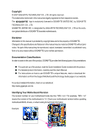
with the product. „ For detailed product information, carefully read the User's Manual. „ For instructions on how to use GIGABYTE's unique features, read or download the information on/from the Support\Motherboard\Technology Guide page on our website. For product-related information, check on our - Gigabyte GA-P35-DS4 | Manual - Page 4
Box Contents ...6 OptionalItems ...6 GA-P35-DS4 Motherboard Layout 7 Block Diagram ...8 Chapter 1 Hardware Installation 9 1-1 Installation Precautions 9 1-2 Product Specifications 10 1-3 Installing the CPU and CPU Cooler 13 1-3-1 Installing the CPU 13 1-3-2 Installing the CPU Cooler 15 - Gigabyte GA-P35-DS4 | Manual - Page 5
with the @BIOS Utility 71 4-3 EasyTune 5 ...73 4-4 Windows Vista ReadyBoost 74 Chapter 5 Appendix ...75 5-1 Configuring SATA Hard Drive(s 75 5-1-1 Configuring Intel® ICH9R SATA Controllers 75 5-1-2 Configuring GIGABYTE SATA2 SATA Controller 81 5-1-3 Making a SATA RAID/AHCI Driver Diskette 87 - Gigabyte GA-P35-DS4 | Manual - Page 6
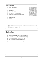
GA-P35-DS4 motherboard Motherboard driver disk User's Manual Quick Installation Guide Intel® LGA775 CPU Installation Guide motherboard image is for reference only. Optional Items 2-port USB 2.0 bracket (Part No. 12CR1-1UB030-51R) 2-port IEEE 1394a bracket (Part No. 12CF1-1IE008-01R) 2-port SATA power - Gigabyte GA-P35-DS4 | Manual - Page 7
GA-P35-DS4 Motherboard Layout RCA SPDIF-1 KB_MS SYS_FAN1 USB ATX_12V_2X LGA775 PWR_FAN PCIE_12V ATX 1394 1394 USB USB GA-P35-DS4 USB LAN F_AUDIO CPU_FAN AUDIO PCIE_1 Intel® P35 RTL8111B PCIE_16_1 NB_FAN FDD DDRII1 DDRII2 DDRII3 DDRII4 CODEC PCIE_2 PCIE_3 SPDIF_O IT8718 - Gigabyte GA-P35-DS4 | Manual - Page 8
IDE Channel GIGABYTE SATA2 PCI Bus TSB43AB23 3 IEEE 1394a LGA775 Processor CPU CLK+/- (400 (O.C.)/333/ 266/200 MHz) Host Interface DDR2 1200 (O.C.)/1066/ 800/667 MHz Intel® P35 Dual Channel Memory MCH CLK (333/266/200 MHz) Intel® ICH9R CODEC Dual BIOS 6 SATA 3Gb/s 12 USB Ports IT8718 - Gigabyte GA-P35-DS4 | Manual - Page 9
discharge (ESD) wrist strap when handling electronic components such as a motherboard, CPU or memory. If you do not have an ESD wrist strap, power supply cable from the motherboard, make sure the power supply has been turned off. • Before turning on the power, make sure the power supply - Gigabyte GA-P35-DS4 | Manual - Page 10
the LGA 775 package (Go to GIGABYTE's website for the latest CPU support list.) Š Support for Intel® Hyper-Threading Technology Š L2 cache varies with CPU Š 1600 (O.C.)/1333/1066/800 MHz FSB Š North Bridge: Intel® P35 Chipset Š South Bridge: Intel® ICH9R Š 4 x 1.8V DDR2 DIMM sockets supporting up to - Gigabyte GA-P35-DS4 | Manual - Page 11
floppy disk drive connector Š 1 x IDE connector Š 8 x SATA 3Gb/s connectors Š 1 x CPU fan header Š 2 x system fan headers Š 1 x power fan header Š 1 x North Bridge fan header Š 1 x front panel header Š 1 x front panel audio header Š 1 x CD In connector Š 1 x S/PDIF In header Š 1 x S/PDIF - Gigabyte GA-P35-DS4 | Manual - Page 12
PCI Express x1 slots become unavailable. (Note 3) Available functions in Easytune may differ by motherboard model. (Note 4) The adjustable CPU voltage range depends on the CPU being used. (Note 5) Due to chipset limitation, Intel ICH9R RAID driver does not support Windows 2000 operating system. GA - Gigabyte GA-P35-DS4 | Manual - Page 13
Setup," "Advanced BIOS Features," for instructions on enabling the HT Technology.) 1-3-1 Installing the CPU A. Locate the alignment keys on the motherboard CPU socket and the notches on the CPU. LGA775 CPU Socket Alignment Key LGA 775 CPU Alignment Key Pin One Corner of the CPU Socket Notch - 13 - Gigabyte GA-P35-DS4 | Manual - Page 14
pin one corner of the CPU socket (or you may align the CPU notches with the socket alignment keys) and gently insert the CPU into position. Step 5: Once the CPU is properly inserted, replace the load plate and push the CPU socket lever back into its locked position. GA-P35-DS4 Motherboard - 14 - - Gigabyte GA-P35-DS4 | Manual - Page 15
. Check that the Male and Female push pins are joined closely. (Refer to your CPU cooler installation manual for instructions on installing the cooler.) Step 5: After the installation, check the back of the motherboard. If the push pin is inserted as the picture above, the installation is complete - Gigabyte GA-P35-DS4 | Manual - Page 16
are installed, a message which says memory is operating in Flex Memory Mode will appear during the POST. Intel® Flex Memory Technology offers greater flexibility to upgrade by allowing different memory sizes to be populated and remain in Dual Channel mode/performance. GA-P35-DS4 Motherboard - 16 - - Gigabyte GA-P35-DS4 | Manual - Page 17
power cord from the power outlet to prevent damage to the memory module. DDR2 DIMMs are not compatible to DDR DIMMs. Be sure to install DDR2 DIMMs on this motherboard. Notch DDR2 DIMM A DDR2 clips at both ends of the memory socket. Place the memory module on the socket. As indicated in the picture on - Gigabyte GA-P35-DS4 | Manual - Page 18
insert the graphics card into the PCI Express x16 slot. Make sure the white latch securely locks the graphics card. • Removing the Card: Press the white latch at the end of the PCI Express x16 slot to release the card and then pull the card straight up from the slot. GA-P35-DS4 Motherboard - 18 - - Gigabyte GA-P35-DS4 | Manual - Page 19
English • The motherboard provides a PCIE_12V power connector, which can supply extra power to the onboard PCI Express x16 slots. When you install two graphics cards, connect the power cable from your power supply to this connector. - 19 - Hardware Installation - Gigabyte GA-P35-DS4 | Manual - Page 20
other ends of the SATA signal cable and SATA power cable to your SATA device. For SATA device in external enclosure, you only need to connect the SATA signal cable. Before connecting the SATA signal cable, make sure to turn off the power of the external enclosure. GA-P35-DS4 Motherboard - 20 - - Gigabyte GA-P35-DS4 | Manual - Page 21
audio system provides an optical digital audio in connector. USB Port The USB port supports the USB 2.0/1.1 specification. Use this port for USB devices such as an USB keyboard/mouse, USB printer, USB from your device and then remove it from the motherboard. • When removing the cable, pull it - Gigabyte GA-P35-DS4 | Manual - Page 22
to perform different functions via the audio software. Only microphones still MUST be connected to the default Mic in jack ( ). Refer to the instructions on setting up a 2/4/5.1/ 7.1-channel audio configuration in Chapter 5, "Configuring 2/4/5.1/7.1-Channel Audio." GA-P35-DS4 Motherboard - 22 - - Gigabyte GA-P35-DS4 | Manual - Page 23
15 7 13 23 17 10 16 9 24 18 21 22 1) ATX_12V_2X 2) ATX (Power Connector) 3) PCIE_12V 4) CPU_FAN 5) SYS_FAN1/SYS_FAN2 6) PWR_FAN 7) NB_FAN 8) FDD 9) IDE to turn off the devices and your computer. Unplug the power cord from the power outlet to prevent damage to the devices. • After installing - Gigabyte GA-P35-DS4 | Manual - Page 24
12V) 6 +12V (Only for 2x4 pin 12V) 7 +12V 8 +12V 12 24 1 13 ATX GA-P35-DS4 Motherboard ATX: Pin No. 1 2 3 4 5 6 7 8 9 10 11 12 Definition Pin No. 3.3V 13 3.3V 14 GND 15 +5V 16 GND 17 +5V 18 GND 19 Power Good 20 5V SB(stand by +5V) 21 +12V 22 +12V(Onlyfor2x12pin ATX - Gigabyte GA-P35-DS4 | Manual - Page 25
English 3) PCIE_12V (Power Connector) This power connector can supply extra power to the PCI Express x16 slots on the motherboard. Connect the power supply cable to this connector when using two graphics cards. Failure to do so may lead to an unstable system. 1 PIin No. Definition 1 NC 2 GND - Gigabyte GA-P35-DS4 | Manual - Page 26
to the fan headers to prevent your CPU, North Bridge and system from overheating. Overheating may result in damage to the CPU/North Bridge or the system may hang. • These fan headers are not configuration jumper blocks. Do not place a jumper cap on the headers. GA-P35-DS4 Motherboard - 26 - - Gigabyte GA-P35-DS4 | Manual - Page 27
groove on the connector. 34 33 2 1 9) IDE (IDE Connector) The IDE connector supports up to two IDE devices such as hard drives and optical drives. Before attaching the IDE cable the IDE devices, read the instructions from the device manufacturers.) 1 2 39 40 - 27 - Hardware Installation - Gigabyte GA-P35-DS4 | Manual - Page 28
number. • A RAID 5 configuration requires at least three hard drives. (The total number of hard drives does not have to be an even number.) • A RAID 10 configuration requires at least four hard drives and the total number of hard drives must be an even number. GA-P35-DS4 Motherboard - 28 - - Gigabyte GA-P35-DS4 | Manual - Page 29
off (S5). Pin No. Definition 1 MPD+ 2 MPD- 1 3 MPD- System Status LED S0 On S1 Blinking S3/S4/S5 Off 13) BAT (Battery) The battery provides power to keep the values (such as BIOS configurations, date, and time information) in the CMOS when the computer is turned off. Replace the - Gigabyte GA-P35-DS4 | Manual - Page 30
. A front panel module mainly consists of power switch, reset switch, power LED, hard drive activity LED, speaker and etc. When connecting your chassis front panel module to this header, make sure the wire assignments and the pin assignments are matched correctly. GA-P35-DS4 Motherboard - 30 - - Gigabyte GA-P35-DS4 | Manual - Page 31
) The front panel audio header supports Intel High Definition audio (HD) and AC'97 audio. You may connect your chassis front panel audio module to this header. Make sure the wire assignments of the module connector match the pin assignments of the motherboard header. Incorrect connection between - Gigabyte GA-P35-DS4 | Manual - Page 32
) This header supports digital S/PDIF in and can connect to an audio device that supports digital audio out via an optional S/PDIF in cable. For purchasing the optional S/PDIF in cable, please contact the local dealer. Pin No. Definition 1 1 Power 2 SPDIFI 3 GND GA-P35-DS4 Motherboard - 32 - Gigabyte GA-P35-DS4 | Manual - Page 33
conform to USB 2.0/1.1 specification. Each USB header can provide two USB ports via an optional USB bracket. For purchasing the optional USB bracket, please contact the local dealer. Pin No. Definition 10 9 1 Power (5V) 2 Power (5V) 3 USB DX- 4 USB DY- 21 5 USB DX+ 6 USB DY+ 7 GND - Gigabyte GA-P35-DS4 | Manual - Page 34
16 17 18 19 20 21 22 23 24 25 26 Definition GND PD6 GND PD7 GND ACKGND BUSY GND PE No Pin SLCT GND GA-P35-DS4 Motherboard - 34 - - Gigabyte GA-P35-DS4 | Manual - Page 35
jumper. Failure to do so may cause damage to the motherboard. • After system restart, go to BIOS Setup to load factory defaults (select Load Optimized Defaults) or manually configure the BIOS settings (refer to Chapter 2, "BIOS Setup," for BIOS configurations). 24) CI (Chassis Intrusion Header) This - Gigabyte GA-P35-DS4 | Manual - Page 36
English GA-P35-DS4 Motherboard - 36 - - Gigabyte GA-P35-DS4 | Manual - Page 37
system configuration settings or to activate certain system features. When the power is turned off, the battery on the motherboard supplies the necessary power to the CMOS to keep the configuration values in the CMOS. To access the BIOS Setup program, press the key during the POST when the - Gigabyte GA-P35-DS4 | Manual - Page 38
, the device boot order will still be based on BIOS Setup settings. You can access Boot Menu again to change the first boot device setting as needed. : GQ-Flash Press the key to access the Q-Flash utility directly without having to enter BIOS Setup first. GA-P35-DS4 Motherboard - 38 - Gigabyte GA-P35-DS4 | Manual - Page 39
Version: F5e) CMOS Setup Utility-Copyright (C) 1984-2007 Award Software ` Standard CMOS Features ` Advanced BIOS Features ` Integrated Peripherals ` Power Management Setup ` PnP/PCI Configurations ` PC Health Status ` MB Intelligent Tweaker(M.I.T.) Load Fail-Safe Defaults Load Optimized Defaults - Gigabyte GA-P35-DS4 | Manual - Page 40
BIOS Features Use this menu to configure the device boot order, advanced features available on the CPU, and the primary display adapter. „ Integrated Peripherals Use this menu to configure all peripheral devices, such as IDE, SATA, USB, integrated audio, and integrated LAN, etc. „ Power Management - Gigabyte GA-P35-DS4 | Manual - Page 41
[None] [None] [None] [None] [None] [None] [None] [None] [None] [None] Drive A Floppy 3 Mode Support [1.44M, 3.5"] [Disabled] Halt On [All, But Keyboard] KLJI: Move Enter: Select F5: Previous Values +/-/PU/PD: Value F10: devices by using one of the three methods below: - 41 - BIOS Setup - Gigabyte GA-P35-DS4 | Manual - Page 42
manually 3 Mode Support Allows you BIOS POST. Base Memory Also called conventional memory. Typically, 640 KB will be reserved for the MS-DOS operating system. Extended Memory The amount of extended memory. Total Memory The total amount of memory installed on the system. GA-P35-DS4 Motherboard - Gigabyte GA-P35-DS4 | Manual - Page 43
the hard drive and to issue warnings when a third party hardware monitor utility is installed. (Default: Disabled) CPU Hyper-Threading (Note) Enables or disables Intel® Hyper-Threading Technology. This feature only works for operating systems that support multi-processors mode. (Default: Enabled - Gigabyte GA-P35-DS4 | Manual - Page 44
. Sets PCI Express graphics card on the second PCIe x16 slot (PCIE_16_2) as the first display. (Note) This item is present only if you install a CPU that supports this feature. For more information about Intel CPUs' unique features, please visit Intel's website. GA-P35-DS4 Motherboard - 44 - Gigabyte GA-P35-DS4 | Manual - Page 45
-2007 Award Software Integrated Peripherals SATA RAID/AHCI Mode SATA Port0-3 Native Mode USB Controller USB 2.0 Controller USB Keyboard Support USB Mouse Support Legacy USB storage detect Azalia Codec Onboard H/W 1394 Onboard H/W LAN ` SMART LAN Onboard LAN Boot ROM Onboard SATA/IDE Device Onboard - Gigabyte GA-P35-DS4 | Manual - Page 46
detecting at Port..... Link Detected --> 100Mbps Cable Length= 30m Link Detected Displays transmission speed Cable Length Displays the approximate length of the attached LAN cable. GA-P35-DS4 Motherboard - 46 - - Gigabyte GA-P35-DS4 | Manual - Page 47
/100/1000Mbps in Windows mode or when the LAN Boot ROM is activated. When a Cable Problem Occurs... If a cable problem occurs on a GIGABYTE SATA 2 chip. (Default: Enabled) Onboard SATA/IDE Ctrl Mode (GIGABYTE SATA2 Chip) Enables or disables RAID for the SATA controller integrated in the GIGABYTE - Gigabyte GA-P35-DS4 | Manual - Page 48
least 1A on the 5VSB lead. (Default: Enabled) Power On by Ring Allows the system to be awakened from an ACPI sleep state by a wake-up signal from a modem that supports wake-up function. (Default: Enabled) (Note) Supported on Windows® Vista® operating system only. GA-P35-DS4 Motherboard - 48 - - Gigabyte GA-P35-DS4 | Manual - Page 49
system stays off upon the return of the AC power. (Default ) Full-On The system is turned on upon the return of the AC power. Memory The system returns to its last known awake state upon the return of the AC power. (Note) Supported on Windows® Vista® operating system only. - 49 - BIOS Setup - Gigabyte GA-P35-DS4 | Manual - Page 50
Award Software PnP/PCI Configurations PCI1 BIOS auto-assigns IRQ to the first PCI slot. (Default) Assigns IRQ 3,4,5,7,9,10,11,12,14,15 to the first PCI slot. BIOS auto-assigns IRQ to the second PCI slot. (Default) Assigns IRQ 3,4,5,7,9,10,11,12,14,15 to the second PCI slot. GA-P35-DS4 Motherboard - Gigabyte GA-P35-DS4 | Manual - Page 51
voltages. Current CPU/System Temperature Displays current CPU/system temperature. Current CPU/SYSTEM/POWER FAN Speed (RPM) Displays current CPU/system/power fan speed. CPU Warning Temperature Sets the warning threshold for CPU temperature. When CPU temperature exceeds the threshold, BIOS will emit - Gigabyte GA-P35-DS4 | Manual - Page 52
, selecting PWM mode may not effectively reduce the fan speed. (Note) Before setting this item to Intel(R) QST, make sure at least DDRII1 or DDRII2 socket in Channel 0 is populated. A small portion of system memory will be shared when Intel® QST is enabled. GA-P35-DS4 Motherboard - 52 - - Gigabyte GA-P35-DS4 | Manual - Page 53
(Note) CPU Host Clock Control x CPU Host Frequency (Mhz) PCI Express Frequency (Mhz) C.I.A. 2 Performance Enhance System Memory Multiplier (SPD) Memory Frequency (Mhz) 667 High Speed DRAM DLL Settings ******** System Voltage Optimized System Voltage Control DDR2 OverVoltage Control PCI-E OverVoltage - Gigabyte GA-P35-DS4 | Manual - Page 54
frequency value is the normal operating frequency of the memory being used; the second is the memory frequency that is automatically adjusted according to the CPU Host Frequency (Mhz) and System Memory Multiplier settings. GA-P35-DS4 Motherboard - 54 - - Gigabyte GA-P35-DS4 | Manual - Page 55
system becomes unstable after you overclock the DDR2 memory, select Option 1 BIOS automatically set the system voltages as required. Manual allows all voltage control items below to be configurable. (Default: Manual) DDR2 OverVoltage Control Allows you to to set memory voltage. Normal Supplies - Gigabyte GA-P35-DS4 | Manual - Page 56
Press on this item and then press the key to load the optimal BIOS default settings. The BIOS defaults settings helps the system to operate in optimum state. Always load the Optimized defaults after updating the BIOS or after clearing the CMOS values. GA-P35-DS4 Motherboard - 56 - - Gigabyte GA-P35-DS4 | Manual - Page 57
Standard CMOS Features ` Advanced BIOS Features ` Integrated Peripherals ` Power Management Setup ` PnP/PCI ConfiguratioEnsnter Password: ` PC boot. In BIOS Setup, you must enter the supervisor password if you wish to make changes to BIOS settings. The user password only allows you to view the BIOS - Gigabyte GA-P35-DS4 | Manual - Page 58
F8: Q-Flash KLJI: Select Item F10: Save & Exit Setup Abandon all Data Press on this item and press the key. This exits the BIOS Setup without saving the changes made in BIOS Setup to the CMOS. Press or to return to the BIOS Setup Main Menu. GA-P35-DS4 Motherboard - 58 - - Gigabyte GA-P35-DS4 | Manual - Page 59
other drivers. • After the drivers are installed, follow the onscreen instructions to restart your system. You can install other applications included in the motherboard driver disk. • For USB 2.0 driver support under the Windows XP operating system, please install the Windows XP Service Pack - Gigabyte GA-P35-DS4 | Manual - Page 60
all the tools and applications that GIGABYTE develops and some free software. You may press the Install button following an item to install it. 3-3 Driver CD Information This page provides information about the drivers, applications and tools in this driver disk. GA-P35-DS4 Motherboard - 60 - - Gigabyte GA-P35-DS4 | Manual - Page 61
English 3-4 Hardware Information This page provides information about the hardware devices on this motherboard. 3-5 Contact Us Check the contacts information of the GIGABYTE headquarter in Taiwan and the overseas branch offices on the last page of this manual. - 61 - Drivers Installation - Gigabyte GA-P35-DS4 | Manual - Page 62
English GA-P35-DS4 Motherboard - 62 - - Gigabyte GA-P35-DS4 | Manual - Page 63
operating system and drivers are installed. • The Windows® XP with SP1 or later • Xpress Recovery and Xpress Recovery2 are different utilities. For example, a backup file created with Xpress Recovery cannot be restored using Xpress Recovery2. • USB hard drives are not supported. • Hard drives in RAID - Gigabyte GA-P35-DS4 | Manual - Page 64
Windows XP as the example operating system.) A. Installing Windows XP and Partitioning the Hard Drive 1. Set CD-ROM drive as the first boot device under "Advanced BIOS Features" in the BIOS NTFS) and begin the installation of the operating system (Figure 3). Figure 3 GA-P35-DS4 Motherboard - 64 - - Gigabyte GA-P35-DS4 | Manual - Page 65
English 4. After the operating system is installed, right-click the My Computer icon on your desktop and select Manage (Figure 4). Go to Computer Management to check disk allocation. Xpress Recovery2 will save the backup file to the unallocated space (black stripe along the top)(Figure 5). Please - Gigabyte GA-P35-DS4 | Manual - Page 66
Software, Inc. Intel P35 BIOS for P35-DS4 F5e . . . . : BIOS Setup : XpressRecovery2 : Boot Menu : Qflash 04/03/2007-P35-ICH9-6A790G0GC- Disk Management to check disk allocation. Figure 12 GA-P35-DS4 Motherboard Xpress Recovery2 will automatically create a new partition to store the - Gigabyte GA-P35-DS4 | Manual - Page 67
backup image file will be present in Disk Management and hard drive space will be freed up (Figure 16). Figure 15 F. Exiting Xpress Recovery2 Select REBOOT to exit Xpress Recovery2. Figure 16 Figure 17 - 67 - Unique Features - Gigabyte GA-P35-DS4 | Manual - Page 68
. Intel P35 BIOS for P35-DS4 F5e . . . . : BIOS Setup : XpressRecovery2 : Boot Menu : Qflash 07/10/2007-P35-ICH9-6A790G0GC-00 Because BIOS flashing is potentially risky, please do it with caution. Inadequate BIOS flashing may result in system malfunction. GA-P35-DS4 Motherboard - Gigabyte GA-P35-DS4 | Manual - Page 69
key to select Update BIOS from Drive and press . • The Save Main BIOS to Drive option allows you to save the current BIOS file. • Q-Flash only supports USB flash drive or hard drives using FAT32/16/12 file system. • If the BIOS update file is saved to a hard drive in RAID/AHCI mode or a hard - Gigabyte GA-P35-DS4 | Manual - Page 70
Setup F11: Save CMOS to BIOS F12: Load CMOS from BIOS Load Optimized Defaults Press to load BIOS defaults Step 6: Select Save & Exit Setup and then press to save settings to CMOS and exit BIOS Setup. The procedure is complete after the system restarts. GA-P35-DS4 Motherboard - 70 - - Gigabyte GA-P35-DS4 | Manual - Page 71
and Using @BIOS: Use the motherboard driver disk included with the motherboard to install @BIOS. • Installing the @BIOS utility. • Accessing the @BIOS utility. Select @BIOS and click Install. Click Start>Program>Gigabyte>BIOS>@BIOS C. Options and Instructions: 1. Save the Current BIOS File In - Gigabyte GA-P35-DS4 | Manual - Page 72
BIOS file matches your motherboard model. Updating the BIOS with an incorrect BIOS file could result in an unbootable system. Step 4: As the system boots, press to enter the BIOS Setup program. Select Load Optimized Defaults and press to load BIOS defaults. GA-P35-DS4 Motherboard - Gigabyte GA-P35-DS4 | Manual - Page 73
the BIOS Setup program. EasyTune 5 provides the following functions (Note 1): overclocking/overvoltage, C.I.A./ M.I.B. (Note 2), smart fan control, and hardware monitoring and warning. (For instructions on using EasyTune5, read or download the information on/from the Support\Motherboard\Utility - Gigabyte GA-P35-DS4 | Manual - Page 74
the slider or spin box. Click Apply and then OK to turn on ReadyBoost. • The USB flash drive must have at least 256 MB of space. • The recommended amount of memory to use for ReadyBoost acceleration is one to three times the amount of RAM installed in your computer. GA-P35-DS4 Motherboard - 74 - - Gigabyte GA-P35-DS4 | Manual - Page 75
(For example, on the GA-P35-DS4 motherboard, the SATAII0, SATAII1, SATAII2, SATAII3, SATAII4 and SATAII5 ports are supported by ICH9R Southbridge.) Then connect the power connector from your power supply to the hard drive. (Note 1) Skip this step if you do not want to create RAID array on the SATA - Gigabyte GA-P35-DS4 | Manual - Page 76
Defaults Step 2: Save changes and exit BIOS Setup. The BIOS Setup menus described in this section may differ from the exact settings for your motherboard. The actual BIOS Setup menu options you will see shall depend on the motherboard you have and the BIOS version. GA-P35-DS4 Motherboard - 76 - - Gigabyte GA-P35-DS4 | Manual - Page 77
C. Configuring a RAID array in RAID BIOS Enter the RAID BIOS setup utility to configure a RAID array. Skip this step and proceed to the installation of Windows operating system for a non-RAID configuration. Step 1: After the POST memory test begins and before the operating system boot begins, look - Gigabyte GA-P35-DS4 | Manual - Page 78
Name : RAID Level : Disks : Strip Size : Capacity : Volume0 RAID0(Stripe) Select Disks 128KB 223.6 GB Create Volume [ HELP ] The following are typical values: RAID0 - 128KB RAID10 - 64KB RAID5 - 64KB [K L ]-Change [TAB]-Next [ESC]-Previous Menu Figure 5 [ENTER]-Select GA-P35-DS4 Motherboard - Gigabyte GA-P35-DS4 | Manual - Page 79
Disk(0) [KL]-Select [ESC]-Exit Figure 7 [ENTER]-Select Menu To exit the ICH9R RAID BIOS utility, press or select Exit in MAIN MENU. Now, you may proceed to create the SATA RAID/AHCI driver diskette and the installation of the SATA RAID/ACHI driver and operating system. - 79 - Appendix - Gigabyte GA-P35-DS4 | Manual - Page 80
abort. Name Volume0 Intel(R) Matrix Storage Manager option ROM v7.5.0.1014 ICH9R wRAID5 Copyright(C) 2003-07 Intel Corporation. All Rights the disks to non-RAID. WARNING: ALL DISK DATA WILL BE DELETED. [K L ]-Select [ESC]-Previous Menu Figure 8 [DEL]-Delete Volume GA-P35-DS4 Motherboard - 80 - - Gigabyte GA-P35-DS4 | Manual - Page 81
for the SATA port. (For example, on this motherboard, the GSATAII0 and GSATAII1 ports are supported by GIGABYTE SATA2.) Then connect the power connector from your power supply to the hard drive. B. Configuring SATA controller mode and device boot order in BIOS Setup Make sure to configure the SATA - Gigabyte GA-P35-DS4 | Manual - Page 82
-RAID [ RAID Disk Drive List ] [IJTAB]-Switch Window [KL]-Select ITEM [ENTER]-Action Figure 3 [ESC]-Exit Note: In the main screen, you can select a hard drive in the Hard Disk Drive List block and press to see detailed information about the selected hard drive. GA-P35-DS4 Motherboard - Gigabyte GA-P35-DS4 | Manual - Page 83
item, use up or down arrow key to select RAID 0 (Stripe), RAID 1 (Mirror), or JBOD (Figure 5). Then press to move onto the next step. GIGABYTE Technology Corp. PCIE-to-SATAII/IDE RAID Controller BIOSv1.06.59 [ Create New RAID ] [ Hard Disk Drive List ] Name: Level: Disks: Block: Size - Gigabyte GA-P35-DS4 | Manual - Page 84
Non-RAID Non-RAID Confirm Creation [ RAID Disk Drive List ] Create RAID [onHethlpe ]select HDD(Y/N)?Y CONFIRM RAID CREATION ALL DATA ON THE SELECTED HARD DISK WILL BE LOST WHEN EXIT WITH SAVING [KL]-Switch Unit [DEL,BS]-Delete Number Figure 7 [ENTER]-Next [ESC]-Abort GA-P35-DS4 Motherboard - Gigabyte GA-P35-DS4 | Manual - Page 85
block to move the selection bar to the RAID Disk Drive List block. Select the array and press . A small window displaying the array information will appear in the center of the screen (Figure 9). GIGABYTE Technology Corp. PCIE-to-SATAII/IDE RAID Controller BIOSv1.06.59 [ Main Menu ] [ Hard - Gigabyte GA-P35-DS4 | Manual - Page 86
120 GB Type/Status RAID Inside RAID Inside [ RAID Disk Drive List ] Model Name ` RDD0: GRAID ALL DATA ON THE RAID WILL LOST!! ARE YOU SURE TO DELETE (Y/N)? N RAID Level Capacity Status 0-Stripe 240 GB Normal Members(HDDx) 01 [KL]-Select RAID GA-P35-DS4 Motherboard [SPACE]-Mark Delete [DEL - Gigabyte GA-P35-DS4 | Manual - Page 87
to a floppy disk. See the instructions below about how to copy the driver in MS-DOS mode(Note). Prepare a startup disk that has CD-ROM support and a blank formatted floppy disk. Step 1: Insert the prepared startup disk and motherboard driver disk in your system. Boot from the startup disk. Once at - Gigabyte GA-P35-DS4 | Manual - Page 88
manufacturer, press S. * If you do not have any device support disks from a mass storage device manufacturer, or do not want to specify additional mass storage devices for use with Windows, press ENTER. S=Specify Additional Device ENTER=Continue F3=Exit Figure 2 GA-P35-DS4 Motherboard - 88 - - Gigabyte GA-P35-DS4 | Manual - Page 89
correct SATA RAID/AHCI driver again from the motherboard driver disk. When the screen as shown below appears, press to continue the driver installation from the floppy disk. The driver installation will be finished in about one minute. Windows Setup Setup will load support for the following - Gigabyte GA-P35-DS4 | Manual - Page 90
motherboard driver disk. When the screen as shown below appears, press to continue the driver installation from the floppy disk. The driver installation will be finished in about one minute. Windows Setup Setup will load support for the following mass storage device(s): GIGABYTE GBB363 RAID - Gigabyte GA-P35-DS4 | Manual - Page 91
Step 4: After the SATA RAID/AHCI driver installation is completed, you can proceed with the Windows XP installation. WindowsXP Professional Setup Welcome to Setup. This port of the Setup program prepares Microsoft(R) Windows (R) XP to run on your computer. To set up Windows XP now, press ENTER - Gigabyte GA-P35-DS4 | Manual - Page 92
to boot from the Windows Vista setup disk and perform standard OS installation steps. When a screen similar to that below appears, select Load Driver. (Figure 8). Figure 8 Step 2: Specify the location where the driver is saved, such as your floppy disk (Figure 9). Figure 9 GA-P35-DS4 Motherboard - Gigabyte GA-P35-DS4 | Manual - Page 93
English Step 3: When a screen as shown in Figure 10 appears, select Intel(R) ICH8R/ICH9R SATA RAID Controller (Note) and press Next. Figure 10 Step 4: After the driver is loaded, select the RAID/AHCI drive(s) where you want to install the operating system and then press Next to continue the OS - Gigabyte GA-P35-DS4 | Manual - Page 94
steps. When a screen similar to that below appears (RAID/AHCI hard drive(s) will not be detected at this stage), select Load Driver. (Figure 12). Figure 12 Step 2: Specify the location where the driver is saved, such as your floppy disk (Figure 13). Figure 13 GA-P35-DS4 Motherboard - 94 - - Gigabyte GA-P35-DS4 | Manual - Page 95
English Step 3: When a screen as shown in Figure 14 appears, select GIGABYTE GBB36X Controller and press Next. Figure 14 Step 4: After the driver is loaded, select the RAID/AHCI drive(s) where you want to install the operating system and then press Next to continue the OS installation (Figure 15). - Gigabyte GA-P35-DS4 | Manual - Page 96
out. • 4 channel audio: Front speaker out and Rear speaker out. • 5.1 channel audio: Front speaker out, Rear speaker out, and Center/Subwoofer speaker out. • 7.1 channel audio: Front speaker out, Rear speaker out, Center/Subwoofer speaker out, and Side speaker out. GA-P35-DS4 Motherboard - 96 - - Gigabyte GA-P35-DS4 | Manual - Page 97
, 4CH Speaker, 6CH Speaker, or 8CH Speaker according to the type of speaker configuration you wish to set up. Step 3: Everytime you connect an audio device to an audio jack, the Connected device box appears. Select the device according to the type of device you connect. Then click OK to complete the - Gigabyte GA-P35-DS4 | Manual - Page 98
digital audio signals to the computer for audio processing. A. Installing the S/PDIF In Cable: Step 1: First, attach the connector at the end of the cable to the SPDIF_IN header on your motherboard. Step 2: Secure the metal bracket to the chassis back panel with a screw. GA-P35-DS4 Motherboard - Gigabyte GA-P35-DS4 | Manual - Page 99
a S/PDIF out Cable Connect a S/PDIF coaxial cable or a S/PDIF optical cable (either one) to an external decoder for transmitting the S/PDIF digital audio signals. S/PDIF Coaxial Cable S/PDIF Optical Cable C. Configuring S/PDIF out: Click the tool icon in the DIGITAL section. In the S/PDIF In/Out - Gigabyte GA-P35-DS4 | Manual - Page 100
source material into multi-channel audio output, creating a virtual surround sound environment(Note). After installing the audio driver, at the center bottom of the Audio Control Panel, you should find , and you will not hear sound from analog speaker or headphone. GA-P35-DS4 Motherboard - 100 - - Gigabyte GA-P35-DS4 | Manual - Page 101
to be output from the S/PDIF OUT. 5-2-4 Configuring Microphone Recording Step 1: After installing the audio driver, the Audio Manager icon will appear in your system tray. Double-click the icon to access the Audio Control Panel. Step 2: Connect your microphone to the Mic in jack (pink) on the back - Gigabyte GA-P35-DS4 | Manual - Page 102
list, select Realtek HD Audio Input. Then set the recording sound level properly. Do NOT mute the recording sound, or you will not hear any sound when playing back the recording you just made. Select Realtek HD Audio Input in the Mixer device list GA-P35-DS4 Motherboard Recording Control - 102 - - Gigabyte GA-P35-DS4 | Manual - Page 103
, and then click Sound Recorder to begin the sound recording. 5-2-5 Using the Sound Recorder Recording the Sound: 1. Make sure you have connected the audio input device (e.g. microphone) to the computer. 2. On the File menu, choose New. 3. To record a sound file, click the Recording but- ton . 4. To - Gigabyte GA-P35-DS4 | Manual - Page 104
setting error 1 long, 1 short: Memory or motherboard error 1 long, 2 short: Monitor or graphics card error 1 long, 3 short: Keyboard error 1 long, 9 short: BIOS ROM error Continuous long beeps: Graphics card not inserted properly Continuous short beeps: Power error GA-P35-DS4 Motherboard - 104 - - Gigabyte GA-P35-DS4 | Manual - Page 105
and solved. Secure the CPU No cooler on the CPU. Connect the CPU cooler power cable to the motherboard. The problem is verified and solved. No Correctly insert the memory into the memory socket. The problem is verified and solved. Press to enter BIOS Setup. Select "Load Fail - Gigabyte GA-P35-DS4 | Manual - Page 106
and solved. END If the procedure above is unable to solve your problem, contact the place of purchase or local dealer for help. Or go to the Support\Technical Service Zone page to submit your question. Our customer service staff will reply you as soon as possible. GA-P35-DS4 Motherboard - 106 - - Gigabyte GA-P35-DS4 | Manual - Page 107
GIGABYTE. Our Commitment to Preserving the Environment In addition to high-efficiency performance, all GIGABYTE motherboards local government office, your household waste disposal service or where you purchased the product for user's manual and we will be glad to help you with your effort. - - Gigabyte GA-P35-DS4 | Manual - Page 108
hazardous substances are not released into the environment and are disposed of properly. China Restriction of Hazardous Substances Table The following table is supplied in compliance with China's Restriction of Hazardous Substances (China RoHS) requirements: GA-P35-DS4 Motherboard - 108 - - Gigabyte GA-P35-DS4 | Manual - Page 109
- 109 - Appendix English - Gigabyte GA-P35-DS4 | Manual - Page 110
English GA-P35-DS4 Motherboard - 110 - - Gigabyte GA-P35-DS4 | Manual - Page 111
(Soporte de habla hispano) FAX: +1-626-854-9339 Correo: [email protected] Tech. Support: http://rma.gigabyte-usa.com Web address: http://www.gigabyte.com.mx Singapore GIGA-BYTE SINGAPORE PTE. LTD. WEB address : http://www.gigabyte.sg Thailand WEB address : http://th.giga-byte.com Vietnam WEB - Gigabyte GA-P35-DS4 | Manual - Page 112
your language in the language list on the top right corner of the website. GIGABYTE Global Service System To submit a technical or non-technical (Sales/ Marketing) question, please link to : http://ggts.gigabyte.com.tw Then select your language to enter the system. GA-P35-DS4 Motherboard - 112 -
-
 1
1 -
 2
2 -
 3
3 -
 4
4 -
 5
5 -
 6
6 -
 7
7 -
8
-
9
-
10
-
11
-
12
-
13
-
14
-
15
-
16
-
17
-
18
-
19
-
20
-
21
-
22
-
23
-
24
-
25
-
26
-
27
-
28
-
29
-
30
-
31
-
32
-
33
-
34
-
35
-
36
-
37
-
38
-
39
-
40
-
41
-
42
-
43
-
44
-
45
-
46
-
47
-
48
-
49
-
50
-
51
-
52
-
53
-
54
-
55
-
56
-
57
-
58
-
59
-
60
-
61
-
62
-
63
-
64
-
65
-
66
-
67
-
68
-
69
-
70
-
71
-
72
-
73
-
74
-
75
-
76
-
77
-
78
-
79
-
80
-
81
-
82
-
83
-
84
-
85
-
86
-
87
-
88
-
89
-
90
-
91
-
92
-
93
-
94
-
95
-
96
-
97
-
98
-
99
-
100
-
101
-
102
-
103
-
104
-
105
-
106
-
107
-
108
-
109
-
110
-
111
-
112
 |
 |

GA-P35-DS4
LGA775 socket motherboard for Intel
®
Core
TM
processor family/
Intel
®
Pentium
®
processor family/Intel
®
Celeron
®
processor family
User's Manual
Rev. 2003
12ME-P35DS4-2003R