Gigabyte GA-P35C-S3 Manual
Gigabyte GA-P35C-S3 Manual
 |
View all Gigabyte GA-P35C-S3 manuals
Add to My Manuals
Save this manual to your list of manuals |
Gigabyte GA-P35C-S3 manual content summary:
- Gigabyte GA-P35C-S3 | Manual - Page 1
GA-P35C-DS3R/ GA-P35C-DS3/ GA-P35C-S3 LGA775 socket motherboard for Intel® CoreTM processor family/ Intel® Pentium® processor family/Intel® Celeron® processor family User's Manual Rev. 2002 12ME-P35CDS3R-2002R * The WEEE marking on the product indicates this product must not be disposed of with user - Gigabyte GA-P35C-S3 | Manual - Page 2
Motherboard GA-P35C-DS3R/GA-P35C-DS3/GA-P35C-S3 Jul. 26, 2007 Motherboard GA-P35C-DS3R/GA-P35C-DS3/ GA-P35C-S3 Jul. 26, 2007 - Gigabyte GA-P35C-S3 | Manual - Page 3
at: http://www.gigabyte.com.tw Identifying Your Motherboard Revision The revision number on your motherboard looks like this: "REV: X.X." For example, "REV: 1.0" means the revision of the motherboard is 1.0. Check your motherboard revision before updating motherboard BIOS, drivers, or when looking - Gigabyte GA-P35C-S3 | Manual - Page 4
...6 GA-P35C-DS3R/DS3/S3 Motherboard Layout 7 Block Diagram ...8 Chapter 1 Hardware Installation 9 1-1 Installation Precautions 9 1-2 Product Specifications 10 1-3 Installing the CPU and CPU Cooler 13 1-3-1 Installing the CPU 13 1-3-2 Installing the CPU Cooler 15 1-4 Installing the Memory 16 - Gigabyte GA-P35C-S3 | Manual - Page 5
the S/PDIF In Cable (Optional 98 5-2-3 Configuring Microphone Recording 100 5-2-4 Using the Sound Recorder 102 5-3 Troubleshooting 103 5-3-1 Frequently Asked Questions 103 5-3-2 Troubleshooting Procedure 104 Regulatory Statements 107 Only the GA-P35C-DS3R supports RAID function. - 5 - - Gigabyte GA-P35C-S3 | Manual - Page 6
Contents GA-P35C-DS3R, GA-P35C-DS3, or GA-P35C-S3 motherboard Motherboard driver disk User's Manual Quick Installation Guide Intel® LGA775 CPU Installation Guide One IDE cable and one floppy disk drive cable GA-P35C-DS3R: Four SATA 3Gb/s cables GA-P35C-DS3/S3: Two SATA 3Gb/s cables GA-P35C-DS3R/DS3 - Gigabyte GA-P35C-S3 | Manual - Page 7
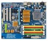
GA-P35C-DS3R/DS3/S3 Motherboard Layout KB_MS ATX_12V CPU_FAN RCA SPDIF LGA775 ATX R_USB1 R_USB2 R_USB3 SYS_FAN2 GA-P35C-DS3R/DS3/S3 USB LAN F_AUDIO AUDIO SYS_FAN1 RTL8111B PCIE_3 PCIE_16 CODEC PCIE_1 PCIE_2 SPDIF_O PCI1 SPDIF_I PCI2 IT8718 PCI3 CD_IN COMA Intel® P35 DDRIII2 - Gigabyte GA-P35C-S3 | Manual - Page 8
Channel GIGABYTE SATA2 / JMicron 368 PCI Bus LGA775 Processor CPU CLK+/- (400 (O.C.)/333/ 266/200 MHz) Host Interface DDR2 1200 (O.C.)/1066/ 800/667 MHz Intel® Dual Channel Memory P35 DDR3 1333/1066/800 MHz Dual Channel Memory MCH CLK (333/266/200 MHz) Intel® ICH9R / ICH9 BIOS 6 SATA - Gigabyte GA-P35C-S3 | Manual - Page 9
manual and follow these procedures: • Prior to installation, do not remove or break motherboard motherboard, CPU or memory. motherboard, make sure the power supply has been turned off. • Before turning on the power, make sure the power supply voltage has been set problem related to the use of - Gigabyte GA-P35C-S3 | Manual - Page 10
LGA 775 package (Go to GIGABYTE's website for the latest CPU support list.) Š Support for Intel® Hyper-Threading Technology Š L2 cache varies with CPU Š 1600 (O.C.)/1333/1066/800 MHz FSB Š North Bridge: Intel® P35 Express Chipset Š South Bridge: Intel® ICH9R / ICH9 DDR3: Š 2 x 1.5V DDR3 DIMM sockets - Gigabyte GA-P35C-S3 | Manual - Page 11
S/PDIF Out connector Š 8 x USB 2.0/1.1 ports Š 1 x RJ-45 port Š 6 x audio jacks (Center/Subwoofer Speaker Out/Rear Speaker Out/Side Speaker Out/Line In/Line Out/Microphone) I/O Controller Š iTE IT8718 chip Only for GA-P35C-DS3R. Only for GA-P35C-DS3. Only for GA-P35C-S3. - 11 - Hardware - Gigabyte GA-P35C-S3 | Manual - Page 12
Whether the CPU fan speed control function is supported will depend on the CPU cooler you install. (Note 4) Available functions in Easytune may differ by motherboard model. (Note 5) Due to chipset limitation, Intel ICH9R RAID driver does not support Windows 2000 operating system. GA-P35C-DS3R/DS3 - Gigabyte GA-P35C-S3 | Manual - Page 13
Setup," "Advanced BIOS Features," for instructions on enabling the HT Technology.) 1-3-1 Installing the CPU A. Locate the alignment keys on the motherboard CPU socket and the notches on the CPU. LGA775 CPU Socket Alignment Key LGA 775 CPU Alignment Key Pin One Corner of the CPU Socket Notch - 13 - Gigabyte GA-P35C-S3 | Manual - Page 14
corner of the CPU socket (or you may align the CPU notches with the socket alignment keys) and gently insert the CPU into position. Step 5: Once the CPU is properly inserted, replace the load plate and push the CPU socket lever back into its locked position. GA-P35C-DS3R/DS3/S3 Motherboard - 14 - - Gigabyte GA-P35C-S3 | Manual - Page 15
. Check that the Male and Female push pins are joined closely. (Refer to your CPU cooler installation manual for instructions on installing the cooler.) Step 5: After the installation, check the back of the motherboard. If the push pin is inserted as the picture above, the installation is complete - Gigabyte GA-P35C-S3 | Manual - Page 16
. • Mixed mode, populating DDR2 and DDR3 memory modules simultaneously is not supported. 1-4-1 Dual Channel Memory Configuration This motherboard provides four DDR2 and two DDR3 memory sockets and supports Dual Channel Technology. After the memory is installed, the BIOS will automatically detect the - Gigabyte GA-P35C-S3 | Manual - Page 17
damage to the memory module. DDR2 and DDR3 DIMMs are not compatible to each other or DDR DIMMs. Do not install DDR DIMMs on this motherboard. Populating DDR2 and DDR3 memory modules simultaneously is not supported. Notch DDR2 DDR3 DDR2 DDR3 DDR2 DIMM DDR3 DIMM A DDR2/DDR3 memory module has - Gigabyte GA-P35C-S3 | Manual - Page 18
graphics card into the PCI Express x16 slot. Make sure the white latch securely locks the graphics card. • Removing the Card: Press the white latch at the end of the PCI Express x16 slot to release the card and then pull the card straight up from the slot. GA-P35C-DS3R/DS3/S3 Motherboard - 18 - - Gigabyte GA-P35C-S3 | Manual - Page 19
secure the SATA bracket to the chassis back panel with a screw. Step 2: Connect the SATA cable from the bracket to the SATA port on your motherboard. Step 3: Step 4: Connect the power Plug one end of the cable from the SATA signal cable into bracket to the power the external SATA supply - Gigabyte GA-P35C-S3 | Manual - Page 20
audio system that supports digital optical audio. Before using this feature, ensure that your audio system provides an optical digital audio in connector. USB Port The USB port supports the USB 2.0/1.1 specification. Use this port for USB devices such as an USB keyboard/mouse, USB printer, USB - Gigabyte GA-P35C-S3 | Manual - Page 21
to the default speakers settings, the ~ audio jacks can be reconfigured to perform different functions via the audio software. Only microphones still MUST be connected to the default Mic in jack ( ). Refer to the instructions on setting up a 2/4/5.1/ 7.1-channel audio configuration in Chapter - Gigabyte GA-P35C-S3 | Manual - Page 22
13 6 4 5 20 15 11 9 8 16 7 10 14 18 19 17 21 12 1) ATX_12V 2) ATX (Power Connector) 3) CPU_FAN 4) SYS_FAN1/SYS_FAN2 5) PWR_FAN 6) FDD 7) IDE1 8) SATAII0/1/2 /3 /4/5 9) GSATAII0 /1 to the connector on the motherboard. Only for GA-P35C-DS3R. GA-P35C-DS3R/DS3/S3 Motherboard - 22 - - Gigabyte GA-P35C-S3 | Manual - Page 23
orientation. The 12V power connector mainly supplies power to the CPU. If the 12V power connector is not connected, the computer compatible with power supplies with 2x10 power connectors. When using a 2x12 power supply, remove the protective cover from the main power connector on the motherboard - Gigabyte GA-P35C-S3 | Manual - Page 24
Connector) This connector is used to connect a floppy disk drive. The types of floppy disk drives supported are: 360 KB, 720 KB, 1.2 MB, 1.44 MB, and 2.88 MB. Before connecting a floppy disk drive, locate the foolproof groove on the connector. 34 33 GA-P35C-DS3R/DS3/S3 Motherboard - 24 - 2 1 - Gigabyte GA-P35C-S3 | Manual - Page 25
/s standard and are compatible with SATA 1.5Gb/s standard. Each SATA connector supports a single SATA device. The ICH9R controller supports RAID 0, RAID 1, RAID 5 and RAID 10. Refer to Chapter 5, "Configuring SATA Hard Drive(s)," for instructions on configuring a RAID array. Pin No. Definition - Gigabyte GA-P35C-S3 | Manual - Page 26
/s standard and are compatible with SATA 1.5Gb/s standard. Each SATA connector supports a single SATA device. The GIGABYTE SATA2 controller supports RAID 0 and RAID 1. Refer to Chapter 5, "Configuring SATA Hard Drive(s)," for instructions on configuring a RAID array. GSATAII0 7 1 1 7 GSATAII1 - Gigabyte GA-P35C-S3 | Manual - Page 27
battery provides power to keep the values (such as BIOS configurations, date, and time information) in the CMOS when the computer is turned off. Replace the battery drops to a low level, or the CMOS values may not be accurate or may be lost. You may clear the CMOS values by removing the battery: 1. - Gigabyte GA-P35C-S3 | Manual - Page 28
startup status by issuing a beep code. One single short beep will be heard if no problem is detected at system startup. If a problem is detected, the BIOS may issue beeps in different patterns to indicate the problem. Refer to Chapter 5, "Troubleshooting," for information about beep codes. • HD (IDE - Gigabyte GA-P35C-S3 | Manual - Page 29
) The front panel audio header supports Intel High Definition audio (HD) and AC'97 audio. You may connect your chassis front panel audio module to this header. Make sure the wire assignments of the module connector match the pin assignments of the motherboard header. Incorrect connection between - Gigabyte GA-P35C-S3 | Manual - Page 30
header supports digital S/PDIF in and can connect to an audio device that supports digital audio out via an optional S/PDIF in cable. For purchasing the optional S/PDIF in cable, please contact the local dealer. 1 Pin No. Definition 1 Power 2 SPDIFI 3 GND GA-P35C-DS3R/DS3/S3 Motherboard - Gigabyte GA-P35C-S3 | Manual - Page 31
, be sure to turn off your computer and unplug the power cord from the power outlet to prevent damage to the USB bracket. 18) COMA (Serial Port Header) The COMA header can provide one serial port via an optional COM port cable. For purchasing the optional COM - Gigabyte GA-P35C-S3 | Manual - Page 32
. Failure to do so may cause damage to the motherboard. • After system restart, go to BIOS Setup to load factory defaults (select Load Optimized Defaults) or manually configure the BIOS settings (refer to Chapter 2, "BIOS Setup," for BIOS configurations). GA-P35C-DS3R/DS3/S3 Motherboard - 32 - - Gigabyte GA-P35C-S3 | Manual - Page 33
English 21) CI (Chassis Intrusion Header) This motherboard provides a chassis detection feature that detects if the chassis cover has been removed. This function requires a chassis with chassis intrusion detection design. Pin No. Definition 1 1 Signal 2 GND - 33 - Hardware Installation - Gigabyte GA-P35C-S3 | Manual - Page 34
English GA-P35C-DS3R/DS3/S3 Motherboard - 34 - - Gigabyte GA-P35C-S3 | Manual - Page 35
the beep codes description. • It is recommended that you not alter the default settings (unless you need to) to prevent system instability or other unexpected results. Inadequately altering the settings may result in system's failure to boot. If this occurs, try to clear the CMOS values and reset - Gigabyte GA-P35C-S3 | Manual - Page 36
Qflash Function Keys B. The POST Screen Motherboard Model BIOS Version Award Modular BIOS v6.00PG, An Energy Star Ally Copyright (C) 1984-2007, Award Software, Inc. Intel P35 BIOS for P35C-DS3R F4d . . . . : BIOS Setup/Q-Flash : XpressRecovery2 : Boot Menu : Qflash 07/09/2007 - Gigabyte GA-P35C-S3 | Manual - Page 37
. (Sample BIOS Version: GA-P35C-DS3R F4d) CMOS Setup Utility-Copyright (C) 1984-2007 Award Software ` Standard CMOS Features ` Advanced BIOS Features ` block on the right side of the submenu. • If you do not find the settings you want in the Main Menu or a submenu, press + to access - Gigabyte GA-P35C-S3 | Manual - Page 38
exit BIOS Setup. (Pressing can also carry out this task.) „ Exit Without Saving Abandon all changes and the previous settings remain in effect. Pressing to the confirmation message will exit BIOS Setup. (Pressing can also carry out this task.) GA-P35C-DS3R/DS3/S3 Motherboard - 38 - Gigabyte GA-P35C-S3 | Manual - Page 39
time. For example, 1 p.m. is 13:0:0. Select the desired field and use the up arrow or down arrow key to set the time. IDE Channel 0/1 Master/Slave IDE HDD Auto-Detection Press to autodetect the parameters of the IDE/SATA device on this channel. Only for GA-P35C-DS3R. - 39 - BIOS Setup - Gigabyte GA-P35C-S3 | Manual - Page 40
the BIOS POST. Base Memory Also called conventional memory. Typically, 640 KB will be reserved for the MS-DOS operating system. Extended Memory The amount of extended memory. Total Memory The total amount of memory installed on the system. Only for GA-P35C-DS3R. GA-P35C-DS3R/DS3/S3 Motherboard - Gigabyte GA-P35C-S3 | Manual - Page 41
CMOS Setup Utility-Copyright (C) 1984-2007 Award Software Advanced BIOS Features ` Hard Disk Boot Priority First Boot Device Second Boot Device Third Boot Device Password Check HDD S.M.A.R.T. Capability CPU Hyper-Threading (Note) Limit CPUID Max. to 3 (Note) No-Execute Memory Protect (Note) CPU - Gigabyte GA-P35C-S3 | Manual - Page 42
first display. (Default) PEG Sets the PCI Express graphics card as the first display. (Note) This item is present only if you install a CPU that supports this feature. For more information about Intel CPUs' unique features, please visit Intel's website. GA-P35C-DS3R/DS3/S3 Motherboard - 42 - - Gigabyte GA-P35C-S3 | Manual - Page 43
driver to enable advanced Serial ATA features such as Native Command Queuing and hot plug. For more information about AHCI, please visit Intel's website. Only for GA-P35C-DS3R. Only for GA-P35C-DS3. Only for GA-P35C-S3. (Note) Supported on Windows® Vista® operating system only. - 43 - BIOS - Gigabyte GA-P35C-S3 | Manual - Page 44
to install operating systems that support Native mode, e.g. Windows XP/2000. SATA Port0-1 Native Mode (Intel ICH9 Southbridge) Specifies the the onboard LAN, set this item to Disabled. Only for GA-P35C-DS3R. Only for GA-P35C-DS3. Only for GA-P35C-S3. GA-P35C-DS3R/DS3/S3 Motherboard - 44 - - Gigabyte GA-P35C-S3 | Manual - Page 45
Function) CMOS Setup Utility motherboard incorporates cable diagnostic feature designed to detect the status of the attached LAN cable. This feature will detect cabling issue in Windows mode or when the LAN Boot ROM is activated. When a Cable Problem Occurs... If a cable problem occurs BIOS Setup - Gigabyte GA-P35C-S3 | Manual - Page 46
Onboard SATA/IDE Ctrl Mode (GIGABYTE SATA2 Chip) Enables or disables RAID for the SATA controller integrated in the GIGABYTE SATA 2 chip or configures the Capabilities Port), ECP+EPP. Only for GA-P35C-DS3R. Only for GA-P35C-DS3. Only for GA-P35C-S3. GA-P35C-DS3R/DS3/S3 Motherboard - 46 - - Gigabyte GA-P35C-S3 | Manual - Page 47
from a PCI or PCIe device. Note: To use this function, you need an ATX power supply providing at least 1A on the 5VSB lead. (Default: Enabled) Power from a modem that supports wake-up function. (Default: Enabled) (Note) Supported on Windows® Vista® operating system only. - 47 - BIOS Setup - Gigabyte GA-P35C-S3 | Manual - Page 48
Enter> again without entering the password to clear the password settings. AC Back Function Determines the state of Memory The system returns to its last known awake state upon the return of the AC power. (Note) Supported on Windows® Vista® operating system only. GA-P35C-DS3R/DS3/S3 Motherboard - Gigabyte GA-P35C-S3 | Manual - Page 49
English 2-7 PnP/PCI Configurations CMOS Setup Utility-Copyright (C) 1984-2007 Award Software PnP/PCI Save F6: Fail-Safe Defaults ESC: Exit F1: General Help F7: Optimized Defaults BIOS auto-assigns IRQ to the first PCI slot. (Default) Assigns IRQ 3,4,5,7,9,10,11,12,14,15 to - Gigabyte GA-P35C-S3 | Manual - Page 50
detection device attached to the motherboard CI header. If the system chassis cover is removed, this field will show "Yes", otherwise it will show "No". To clear the chassis intrusion status record, set Reset Case Open Status to Enabled, save the settings to CMOS, and then restart your system - Gigabyte GA-P35C-S3 | Manual - Page 51
speed. Auto Lets BIOS control CPU fan speed. (Default) Intel(R) QST Allows CPU fan speed to be controlled by the Intel Quiet System Technology (QST). This feature requires the installation of Intel Host Embedded Control Interface (HECI) driver from the motherboard driver disk. Legacy Allows - Gigabyte GA-P35C-S3 | Manual - Page 52
fails to boot after overclocking, please wait for 20 seconds to allow for automated system reboot, or clear the CMOS values to reset the board to default values. (Default: Disabled) (Note) This item appears only if you install a CPU that supports this feature. GA-P35C-DS3R/DS3/S3 Motherboard - 52 - Gigabyte GA-P35C-S3 | Manual - Page 53
is automatically adjusted according to the CPU Host Frequency (Mhz) and System Memory Multiplier settings. High Speed DRAM DLL Settings Provides two different memory timing configurations. If your system becomes unstable after you overclock the DDR2/DDR3 memory, select Option 1 or Option 2 to - Gigabyte GA-P35C-S3 | Manual - Page 54
to manually set the system voltages. Auto lets BIOS automatically set the system voltages as required. Manual allows all voltage control items below to be configurable. (Default: Manual) DDR2 /DDR3 OverVoltage Control Allows you to to set memory voltage. Normal Supplies the memory voltage - Gigabyte GA-P35C-S3 | Manual - Page 55
CMOS from BIOS Load Optimized Defaults Press on this item and then press the key to load the optimal BIOS default settings. The BIOS defaults settings helps the system to operate in optimum state. Always load the Optimized defaults after updating the BIOS or after clearing the CMOS - Gigabyte GA-P35C-S3 | Manual - Page 56
to view the BIOS settings but not to make changes. To clear the password, press on the password item and when requested for the password, press again. The message "PASSWORD DISABLED" will appear, indicating the password has been cancelled. GA-P35C-DS3R/DS3/S3 Motherboard - 56 - - Gigabyte GA-P35C-S3 | Manual - Page 57
Utility-Copyright (C) 1984-2007 Award Software ` Standard CMOS Features Load Fail-Safe Defaults ` Advanced BIOS Features Load Optimized Defaults ` Integrated Peripherals Set Supervisor Password ` Power Management Setup Save to CMOS and EXIT (SYe/tNU)?seYr Password ` PnP/PCI Configurations - Gigabyte GA-P35C-S3 | Manual - Page 58
English GA-P35C-DS3R/DS3/S3 Motherboard - 58 - - Gigabyte GA-P35C-S3 | Manual - Page 59
other drivers. • After the drivers are installed, follow the onscreen instructions to restart your system. You can install other applications included in the motherboard driver disk. • For USB 2.0 driver support under the Windows XP operating system, please install the Windows XP Service Pack - Gigabyte GA-P35C-S3 | Manual - Page 60
the tools and applications that GIGABYTE develops and some free software. You may press the Install button following an item to install it. 3-3 Driver CD Information This page provides information about the drivers, applications and tools in this driver disk. GA-P35C-DS3R/DS3/S3 Motherboard - 60 - - Gigabyte GA-P35C-S3 | Manual - Page 61
English 3-4 Hardware Information This page provides information about the hardware devices on this motherboard. 3-5 Contact Us Check the contacts information of the GIGABYTE headquarter in Taiwan and the overseas branch offices on the last page of this manual. - 61 - Drivers Installation - Gigabyte GA-P35C-S3 | Manual - Page 62
English GA-P35C-DS3R/DS3/S3 Motherboard - 62 - - Gigabyte GA-P35C-S3 | Manual - Page 63
system soon after the operating system and drivers are installed. • The amount of data Intel® x86 platform • At least 64 MB of system memory • VESA compatible graphics card • Windows® 2000 with SP3 or later; Windows USB hard drives are not supported. • Hard drives in RAID/AHCI mode are not supported - Gigabyte GA-P35C-S3 | Manual - Page 64
Windows XP as the example operating system.) A. Installing Windows XP and Partitioning the Hard Drive 1. Set CD-ROM drive as the first boot device under "Advanced BIOS Features" in the BIOS begin the installation of the operating system (Figure 3). Figure 3 GA-P35C-DS3R/DS3/S3 Motherboard - 64 - - Gigabyte GA-P35C-S3 | Manual - Page 65
English 4. After the operating system is installed, right-click the My Computer icon on your desktop and select Manage (Figure 4). Go to Computer Management to check disk allocation. Xpress Recovery2 will save the backup file to the unallocated space (black stripe along the top)(Figure 5). Please - Gigabyte GA-P35C-S3 | Manual - Page 66
v6.00PG, An Energy Star Ally Copyright (C) 1984-2007, Award Software, Inc. Intel P35 BIOS for P35C-DS3R F4d . . . . : BIOS Setup/Q-Flash : XpressRecovery2 : Boot Menu : Qflash 07/09/2007-P35-ICH9-6A790G0BC-00 Figure 9 C. Using the Backup Function in Xpress Recovery2 1. Select - Gigabyte GA-P35C-S3 | Manual - Page 67
English D. Using the Restore Function in Xpress Recovery2 Select RESTORE to restore the backup to your hard drive in case the system breaks down. The RESTORE option will not be present if no backup is created before (Figure 13, 14). Figure 13 Figure 14 E. Removing the Backup 1. If you wish to - Gigabyte GA-P35C-S3 | Manual - Page 68
BIOS update file is saved to a hard drive in RAID/AHCI mode or a hard drive attached to an independent IDE/SATA controller, use the key during the POST to access Q-Flash. Award Modular BIOS v6.00PG, An Energy Star Ally Copyright (C) 1984-2007, Award Software, Inc. Intel P35 BIOS for P35C-DS3R - Gigabyte GA-P35C-S3 | Manual - Page 69
arrow key to select Update BIOS from Drive and press . • The Save Main BIOS to Drive option allows you to save the current BIOS file. • Q-Flash only supports USB flash drive or hard drives using FAT32/16/12 file system. • If the BIOS update file is saved to a hard drive in RAID/AHCI mode or - Gigabyte GA-P35C-S3 | Manual - Page 70
F11: Save CMOS to BIOS F12: Load CMOS from BIOS Load Optimized Defaults Press to load BIOS defaults Step 6: Select Save & Exit Setup and then press to save settings to CMOS and exit BIOS Setup. The procedure is complete after the system restarts. GA-P35C-DS3R/DS3/S3 Motherboard - 70 - - Gigabyte GA-P35C-S3 | Manual - Page 71
1. If your system supports Intel® Hyper-Threading technology, disable this function in BIOS Setup. 2. In Windows, close all applications and TSR (Terminate and Stay Resident) programs. This helps prevent unexpected failures when performing a BIOS update. 3. During the BIOS update process, ensure the - Gigabyte GA-P35C-S3 | Manual - Page 72
your motherboard model. Updating the BIOS with an incorrect BIOS file could result in an unbootable system. Step 4: As the system boots, press to enter the BIOS Setup program. Select Load Optimized Defaults and press to load BIOS defaults. GA-P35C-DS3R/DS3/S3 Motherboard - 72 - Gigabyte GA-P35C-S3 | Manual - Page 73
frequency Shows the information of the current function Visits GIGABYTE website Displays EasyTuneTM 5 help screen Quits or minimizes EasyTuneTM 5 Incorrectly doing overclock/overvoltage may result in damage to CPU, chipset, or memory and reduce the useful life of these components. Before you do the - Gigabyte GA-P35C-S3 | Manual - Page 74
or spin box. Click Apply and then OK to turn on ReadyBoost. • The USB flash drive must have at least 256 MB of space. • The recommended amount of memory to use for ReadyBoost acceleration is one to three times the amount of RAM installed in your computer. GA-P35C-DS3R/DS3/S3 Motherboard - 74 - - Gigabyte GA-P35C-S3 | Manual - Page 75
is set to AHCI or RAID mode. (Note 3) Due to chipset limitation, Intel ICH9R RAID driver does not support Windows 2000 operating system. Only the GA-P35C-DS3R supports RAID function. The instructions on configurig a RAID array in this chapter are for users of the GA-P35C-DS3R motherboard. - 75 - Gigabyte GA-P35C-S3 | Manual - Page 76
Step 2: Save changes and exit BIOS Setup. The BIOS Setup menus described in this section may differ from the exact settings for your motherboard. The actual BIOS Setup menu options you will see shall depend on the motherboard you have and the BIOS version. GA-P35C-DS3R/DS3/S3 Motherboard - 76 - - Gigabyte GA-P35C-S3 | Manual - Page 77
C. Configuring a RAID array in RAID BIOS Enter the RAID BIOS setup utility to configure a RAID array. Skip this step and proceed to the installation of Windows operating system for a non-RAID configuration. Step 1: After the POST memory test begins and before the operating system boot begins, look - Gigabyte GA-P35C-S3 | Manual - Page 78
223.6 GB Create Volume [ HELP ] The following are typical values: RAID0 - 128KB RAID10 - 64KB RAID5 - 64KB [K L ]-Change [TAB]-Next [ESC]-Previous Menu Figure 5 [ENTER]-Select GA-P35C-DS3R/DS3/S3 Motherboard - 78 - - Gigabyte GA-P35C-S3 | Manual - Page 79
Storage Manager option ROM v7.5.0.1014 ICH9R wRAID5 Copyright(C) 2003-07 Intel Corporation. All Rights Reversed. [ MAIN MENU ] 1. Create RAID Volume 2. Delete RAID Volume 3. Reset Disks to Non-RAID 4. Exit RAID Volumes : ID Name 0 Volume0 Physical Disks : Port Drive Model 0 ST3120026AS - Gigabyte GA-P35C-S3 | Manual - Page 80
. Name Volume0 Intel(R) Matrix Storage Manager option ROM v7.5.0.1014 ICH9R wRAID5 Copyright(C) 2003-07 Intel Corporation. All reset the disks to non-RAID. WARNING: ALL DISK DATA WILL BE DELETED. [K L ]-Select [ESC]-Previous Menu Figure 8 [DEL]-Delete Volume GA-P35C-DS3R/DS3/S3 Motherboard - Gigabyte GA-P35C-S3 | Manual - Page 81
to create RAID, set this item to IDE or AHCI, depending on your need. CMOS Setup Utility-Copyright (C) 1984-2007 Award Software Integrated Peripherals SATA RAID/AHCI Mode SATA Port0-3 Native Mode USB Controller USB 2.0 Controller USB Keyboard Support USB Mouse Support Legacy USB storage detect - Gigabyte GA-P35C-S3 | Manual - Page 82
RAID Disk Drive List ] [IJTAB]-Switch Window [KL]-Select ITEM [ENTER]-Action Figure 3 [ESC]-Exit Note: In the main screen, you can select a hard drive in the Hard Disk Drive List block and press to see detailed information about the selected hard drive. GA-P35C-DS3R/DS3/S3 Motherboard - Gigabyte GA-P35C-S3 | Manual - Page 83
the main screen, press on the Create RAID Disk Drive item. Then the Create New RAID screen appears (Figure 4). GIGABYTE Technology Corp. PCIE-to-SATAII/IDE RAID Controller BIOSv1.06.59 [ Create New RAID ] [ Hard Disk Drive List ] Name: Level: Disks: Block: Size: GRAID_ 0-Stripe Select - Gigabyte GA-P35C-S3 | Manual - Page 84
Non-RAID Non-RAID Confirm Creation [ RAID Disk Drive List ] Create RAID [onHethlpe ]select HDD(Y/N)?Y CONFIRM RAID CREATION ALL DATA ON THE SELECTED HARD DISK WILL BE LOST WHEN EXIT WITH SAVING [KL]-Switch Unit [DEL,BS]-Delete Number Figure 7 [ENTER]-Next GA-P35C-DS3R/DS3/S3 Motherboard - Gigabyte GA-P35C-S3 | Manual - Page 85
block to move the selection bar to the RAID Disk Drive List block. Select the array and press . A small window displaying the array information will appear in the center of the screen (Figure 9). GIGABYTE Technology Corp. PCIE-to-SATAII/IDE RAID Controller BIOSv1.06.59 [ Main Menu ] [ Hard - Gigabyte GA-P35C-S3 | Manual - Page 86
RAID Inside [ RAID Disk Drive List ] Model Name ` RDD0: GRAID ALL DATA ON THE RAID WILL LOST!! ARE YOU SURE TO DELETE (Y/N)? N RAID Level Capacity Status 0-Stripe 240 GB Normal Members(HDDx) 01 [KL]-Select RAID [SPACE]-Mark Delete [DEL]-Confirm Figure 11 GA-P35C-DS3R/DS3/S3 Motherboard - Gigabyte GA-P35C-S3 | Manual - Page 87
XP/Vista 32-bit operating system or (8) Intel Matrix Storage Manager 64 bit for Windows 64-bit. • For GIGABYTE SATA2 SATA controller, select E) GIGABYTE SATA-RAID Driver 32Bit for Windows XP/Vista 32-bit operating system or F) GIGABYTE SATA-RAID Driver 64Bit for Windows 64-bit. Your system will then - Gigabyte GA-P35C-S3 | Manual - Page 88
the SATA RAID/AHCI driver diskette and configured the required BIOS settings, you are ready to install Windows Vista/XP/2000 onto your hard drive(s). The following is an example of Windows XP and Vista installation. A. Installing Windows XP Step 1: Restart your system to boot from the Windows XP - Gigabyte GA-P35C-S3 | Manual - Page 89
If you set the SATA RAID/AHCI Mode item in BIOS Setup to RAID mode, select Intel(R) ICH8R/ICH9R SATA RAID Controller. (Select Intel(R) ICH9 SATA AHCIController (Desktop ICH9R) for AHCI mode.) Windows Setup You have chosen to configure a SCSI Adapter for use with Windows, using a device support disk - Gigabyte GA-P35C-S3 | Manual - Page 90
motherboard driver disk. When the screen as shown below appears, press to continue the driver installation from the floppy disk. The driver installation will be finished in about one minute. Windows Setup Setup will load support for the following mass storage device(s): GIGABYTE GBB363 RAID - Gigabyte GA-P35C-S3 | Manual - Page 91
Step 4: After the SATA controller driver installation is completed, you can proceed with the Windows XP installation. WindowsXP Professional Setup Welcome to Setup. This port of the Setup program prepares Microsoft(R) Windows (R) XP to run on your computer. To set up Windows XP now, press ENTER. To - Gigabyte GA-P35C-S3 | Manual - Page 92
from the Windows Vista setup disk and perform standard OS installation steps. When a screen similar to that below appears, select Load Driver. (Figure 8). Figure 8 Step 2: Specify the location where the driver is saved, such as your floppy disk (Figure 9). Figure 9 GA-P35C-DS3R/DS3/S3 Motherboard - Gigabyte GA-P35C-S3 | Manual - Page 93
the driver is loaded, select the RAID/AHCI drive(s) where you want to install the operating system and then press Next to continue the OS installation (Figure 11). Figure 11 (Note) The item displayed in Figure 10 will be shown as Intel(R) ICH9 SATA AHCI Controller when the SATA controllers are set - Gigabyte GA-P35C-S3 | Manual - Page 94
. When a screen similar to that below appears (RAID/AHCI hard drive(s) will not be detected at this stage), select Load Driver. (Figure 12). Figure 12 Step 2: Specify the location where the driver is saved, such as your floppy disk (Figure 13). Figure 13 GA-P35C-DS3R/DS3/S3 Motherboard - 94 - - Gigabyte GA-P35C-S3 | Manual - Page 95
English Step 3: When a screen as shown in Figure 14 appears, select GIGABYTE GBB36X Controller and press Next. Figure 14 Step 4: After the driver is loaded, the screen will show the RAID/AHCI hard drive(s). Select the location where you want to install the operating system and then press Next to - Gigabyte GA-P35C-S3 | Manual - Page 96
Before installing the audio driver, make sure the "Microsoft UAA Bus driver for High Definition Audio" has been installed from the motherboard driver disk and your operating system has been updated with the latest Service Pack for Windows. (Note) 2/4/5.1/7.1 Channel Audio Configurations: Refer to - Gigabyte GA-P35C-S3 | Manual - Page 97
English Step 2: Click the Audio I/O tab. In the speaker list on the left, select 2CH Speaker, 4CH Speaker, 6CH Speaker, or 8CH Speaker according to the type of speaker configuration you wish to set up. Step 3: Everytime you connect an audio device to an audio jack, the Connected device box appears. - Gigabyte GA-P35C-S3 | Manual - Page 98
input digital audio signals to the computer for audio processing. A. Installing the S/PDIF In Cable: Step 1: First, attach the connector at the end of the cable to the SPDIF_I header on your motherboard. Step 2: Secure the metal bracket to the chassis back panel with a screw. GA-P35C-DS3R/DS3/S3 - Gigabyte GA-P35C-S3 | Manual - Page 99
cable (either one) to an external decoder for transmitting the S/PDIF digital audio signals. S/PDIF Coaxial Cable S/PDIF Optical Cable B. Configuring S/PDIF out: the tool icon in the DIGITAL section. In the S/PDIF In/Out Settings dialog box, select an output sampling rate and select (or disable) the - Gigabyte GA-P35C-S3 | Manual - Page 100
Microphone Recording Step 1: After installing the audio driver, the Audio Manager icon will appear in your system tray. Double-click the icon to access the Audio Control Panel. Step 2: Connect your microphone click it to open the volume control panel GA-P35C-DS3R/DS3/S3 Motherboard - 100 - - Gigabyte GA-P35C-S3 | Manual - Page 101
or Front Green In in Master Volume. It is recommended that you set the volume at a middle level. To hear the sound being recorded go to Options and click Properties. In the Mixer device list, select Realtek HD Audio Input. Then set the recording sound level properly. Do NOT mute the recording - Gigabyte GA-P35C-S3 | Manual - Page 102
the sound recording. 5-2-4 Using the Sound Recorder Recording the Sound: 1. Make sure you have connected the audio input device (e.g. microphone) to the computer. 2. On the File menu, choose New. 3. To record a file or the Fast Backward button to the end. GA-P35C-DS3R/DS3/S3 Motherboard - 102 - - Gigabyte GA-P35C-S3 | Manual - Page 103
during the POST mean? A: The following Award BIOS beep code descriptions may help you identify possible computer problems. (For reference only.) 1 short: System boots successfully 2 short: CMOS setting error 1 long, 1 short: Memory or motherboard error 1 long, 2 short: Monitor or graphics card - Gigabyte GA-P35C-S3 | Manual - Page 104
the memory into the memory socket. The problem is verified and solved. Press to enter BIOS Setup. Select "Load Fail-Safe Defaults" (or "Load Optimized Defaults"). Select "Save & Exit Setup" to save changes and exit BIOS Setup. A (Continued...) GA-P35C-DS3R/DS3/S3 Motherboard - 104 - Gigabyte GA-P35C-S3 | Manual - Page 105
CPU socket might fail. The problem is verified and solved. No The graphics card, expansion slot, or monitor might fail. The problem is verified and solved. Check if the keyboard is working properly. Yes Press to enter BIOS Setup. Select "Load Fail-Safe Defaults" (or "Load Optimized - Gigabyte GA-P35C-S3 | Manual - Page 106
English GA-P35C-DS3R/DS3/S3 Motherboard - 106 - - Gigabyte GA-P35C-S3 | Manual - Page 107
commitment by GIGABYTE. Our Commitment to Preserving the Environment In addition to high-efficiency performance, all GIGABYTE motherboards fulfill European may contact us at the Customer Care number listed in your product's user's manual and we will be glad to help you with your effort. - 107 - Gigabyte GA-P35C-S3 | Manual - Page 108
disposed of properly. China Restriction of Hazardous Substances Table The following table is supplied in compliance with China's Restriction of Hazardous Substances (China RoHS) requirements: GA-P35C-DS3R/DS3/S3 Motherboard - 108 - - Gigabyte GA-P35C-S3 | Manual - Page 109
- 109 - Appendix English - Gigabyte GA-P35C-S3 | Manual - Page 110
English GA-P35C-DS3R/DS3/S3 Motherboard - 110 - - Gigabyte GA-P35C-S3 | Manual - Page 111
(Soporte de habla hispano) FAX: +1-626-854-9339 Correo: [email protected] Tech. Support: http://rma.gigabyte-usa.com Web address: http://www.gigabyte.com.mx Singapore GIGA-BYTE SINGAPORE PTE. LTD. WEB address : http://www.gigabyte.sg Thailand WEB address : http://th.giga-byte.com Vietnam WEB - Gigabyte GA-P35C-S3 | Manual - Page 112
Technology Co., Ltd. in SERBIA & MONTENEGRO WEB address : http://www.gigabyte.co.yu You may go to the GIGABYTE website, select your language in the language list on the top right corner of the website. GIGABYTE Global Service System To submit a technical or non-technical (Sales/ Marketing) question
-
 1
1 -
 2
2 -
 3
3 -
 4
4 -
 5
5 -
 6
6 -
 7
7 -
8
-
9
-
10
-
11
-
12
-
13
-
14
-
15
-
16
-
17
-
18
-
19
-
20
-
21
-
22
-
23
-
24
-
25
-
26
-
27
-
28
-
29
-
30
-
31
-
32
-
33
-
34
-
35
-
36
-
37
-
38
-
39
-
40
-
41
-
42
-
43
-
44
-
45
-
46
-
47
-
48
-
49
-
50
-
51
-
52
-
53
-
54
-
55
-
56
-
57
-
58
-
59
-
60
-
61
-
62
-
63
-
64
-
65
-
66
-
67
-
68
-
69
-
70
-
71
-
72
-
73
-
74
-
75
-
76
-
77
-
78
-
79
-
80
-
81
-
82
-
83
-
84
-
85
-
86
-
87
-
88
-
89
-
90
-
91
-
92
-
93
-
94
-
95
-
96
-
97
-
98
-
99
-
100
-
101
-
102
-
103
-
104
-
105
-
106
-
107
-
108
-
109
-
110
-
111
-
112
 |
 |

GA-P35C-DS3R/
GA-P35C-DS3/
GA-P35C-S3
LGA775 socket motherboard for Intel
®
Core
TM
processor family/
Intel
®
Pentium
®
processor family/Intel
®
Celeron
®
processor family
User's Manual
Rev. 2002
12ME-P35CDS3R-2002R
*
The WEEE marking on the product indicates this product must not be disposed of with user's other household waste
and must be handed over to a designated collection point for the recycling of waste electrical and electronic equipment!!
*
The WEEE marking applies only in European Union's member states.