Gigabyte GA-P35T-DS3P Manual
Gigabyte GA-P35T-DS3P Manual
 |
View all Gigabyte GA-P35T-DS3P manuals
Add to My Manuals
Save this manual to your list of manuals |
Gigabyte GA-P35T-DS3P manual content summary:
- Gigabyte GA-P35T-DS3P | Manual - Page 1
GA-P35T-DS3P LGA775 socket motherboard for Intel® CoreTM processor family/ Intel® Pentium® processor family/Intel® Celeron® processor family User's Manual Rev. 1001 12ME-P35TDS3P-1001R * The WEEE marking on the product indicates this product must not be disposed of with user's other household waste - Gigabyte GA-P35T-DS3P | Manual - Page 2
Motherboard GA-P35T-DS3P Jun. 4, 2007 Motherboard GA-P35T-DS3P Jun. 4, 2007 - Gigabyte GA-P35T-DS3P | Manual - Page 3
with the product. „ For detailed product information, carefully read the User's Manual. „ For instructions on how to use GIGABYTE's unique features, read or download the information on/from the Support\Motherboard\Technology Guide page on our website. For product-related information, check on our - Gigabyte GA-P35T-DS3P | Manual - Page 4
Table of Contents OptionalItems ...6 Box Contents ...6 GA-P35T-DS3P Motherboard Layout 7 Block Diagram ...8 Chapter 1 Hardware Installation 9 1-1 Bracket 20 1-7 Back Panel Connectors 21 1-8 Internal Connectors 23 Chapter 2 BIOS Setup 35 2-1 Startup Screen 36 2-2 The Main Menu 37 2-3 Standard - Gigabyte GA-P35T-DS3P | Manual - Page 5
with the @BIOS Utility 69 4-3 EasyTune 5 ...71 4-4 Windows Vista ReadyBoost 72 Chapter 5 Appendix ...73 5-1 Configuring SATA Hard Drive(s 73 5-1-1 Configuring Intel® ICH9R SATA Controllers 73 5-1-2 Configuring GIGABYTE SATA2 SATA Controller 79 5-1-3 Making a SATA RAID/AHCI Driver Diskette 85 - Gigabyte GA-P35T-DS3P | Manual - Page 6
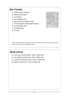
Contents GA-P35T-DS3P motherboard Motherboard Driver Disk User's Manual Quick Installation Guide Intel® LGA775 CPU Installation Guide One subject to change without notice. Optional Items 2-port USB 2.0 bracket (Part No. 12CR1-1UB030-51/R) 4-port USB 2.0 bracket (Part No. 12CR1-1UB030-21/R) 2-port - Gigabyte GA-P35T-DS3P | Manual - Page 7
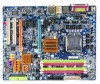
GA-P35T-DS3P Motherboard Layout KB_MS SYS_FAN1 COAXIAL OPTICAL ATX_12V_2X LGA775 PWR_FAN PCIE_12V COM LPT 1394 GA-P35T-DS3P ATX USB LAN USB CPU_FAN AUDIO Intel® P35 TSB43AB23 CI F1_1394 F_USB1 F2_1394 GSATAII0 SATAII5 SATAII3 GIGABYTE SATA2 IDE F_PANEL GSATAII1 PWR_LED - 7 - - Gigabyte GA-P35T-DS3P | Manual - Page 8
3Gb/s ATA-133/100/66/ 33 IDE Channel PCI Bus GIGABYTE SATA2 TSB43AB23 3 IEEE 1394a Host Interface DDR3 1333/1066/800 MHz Intel® P35 Dual Channel Memory MCH CLK (333/266/200 MHz) Intel® ICH9R CODEC Dual BIOS 6 SATA 3Gb/s 12 USB Ports IT8718 Floppy LPT Port COM Port PS/2 KB/Mouse 2 PCI - Gigabyte GA-P35T-DS3P | Manual - Page 9
, carefully read the user's manual and follow these procedures: • Prior to installation, do not remove or break motherboard S/N (Serial Number) sticker or you are uncertain about any installation steps or have a problem related to the use of the product, please consult a certified computer technician. - Gigabyte GA-P35T-DS3P | Manual - Page 10
3Gb/s connectors (GSATAII0, GSATAII1) supporting up to 2 SATA 3Gb/s devices - Support for SATA RAID 0, RAID 1, and JBOD Š T.I. TSB43AB23 chip Š Up to 3 IEEE 1394a ports (1 on the back panel, 2 via the IEEE 1394 bracket connected to the internal IEEE 1394 headers) GA-P35T-DS3P Motherboard - 10 - - Gigabyte GA-P35T-DS3P | Manual - Page 11
USB 2.0/1.1 ports (4 on the back panel, 8 via the USB brackets connected to the internal USB headers) Internal Connectors Š 1 x 24-pin ATX main power connector Š 1 x 8-pin ATX 12V power connector Š 1 x 4-pin PCIe Š 1 x S/PDIF In header Š 4 x USB 2.0/1.1 headers Š 2 x IEEE 1394a headers Š 1 - Gigabyte GA-P35T-DS3P | Manual - Page 12
x16 slot (PCIE_16_2) is in use, the three PCI Express x1 slots become unavailable. (Note 3) Available functions in Easytune may differ by motherboard model. (Note 4) Due to chipset limitation, Intel ICH9R RAID driver does not support Windows 2000 operating system. GA-P35T-DS3P Motherboard - 12 - - Gigabyte GA-P35T-DS3P | Manual - Page 13
is optimized for HT Technology • A BIOS that supports HT Technology and has it enabled (Refer to Chapter 2, "BIOS Setup," "Advanced BIOS Features," for instructions on enabling the HT Technology.) 1-3-1 Installing the CPU A. Locate the alignment keys on the motherboard CPU socket and the notches on - Gigabyte GA-P35T-DS3P | Manual - Page 14
English B. Follow the steps below to correctly install the CPU into the motherboard CPU socket. Before installing the CPU, make sure to turn off the computer and unplug inserted, replace the load plate and push the CPU socket lever back into its locked position. GA-P35T-DS3P Motherboard - 14 - - Gigabyte GA-P35T-DS3P | Manual - Page 15
that the Male and Female push pins are joined closely. (Refer to your CPU cooler installation manual for instructions on installing the cooler.) Step 5: After the installation, check the back of the motherboard. If the push pin is inserted as the picture above, the installation is complete. Step - Gigabyte GA-P35T-DS3P | Manual - Page 16
Dual Channel Memory Configuration This motherboard provides four DDR3 memory sockets and supports Dual Channel Technology. After the memory is installed, the BIOS will automatically detect the specifications be populated and remain in Dual Channel mode/performance. GA-P35T-DS3P Motherboard - 16 - - Gigabyte GA-P35T-DS3P | Manual - Page 17
unplug the power cord from the power outlet to prevent damage to the memory module. DDR3 and DDR2 DIMMs are not compatible to each other or DDR DIMMs. Be sure to install DDR3 DIMMs on this motherboard. Notch A DDR3 memory module has a notch, so it can only fit in one direction. Follow the steps - Gigabyte GA-P35T-DS3P | Manual - Page 18
expansion card: • Make sure the motherboard supports the expansion card. Carefully read the manual that came with your expansion card. necessary, go to BIOS Setup to make any required BIOS changes for your expansion card(s). 7. Install the driver provided with the GA-P35T-DS3P Motherboard - 18 - - Gigabyte GA-P35T-DS3P | Manual - Page 19
latch at the end of the PCI Express x16 slot to release the card and then pull the card straight up from the slot. • The motherboard provides a PCIE_12V power connector, which can supply extra power to the onboard PCI Express x16 slots. When you install two graphics cards, connect the power - Gigabyte GA-P35T-DS3P | Manual - Page 20
panel with a screw. Step 2: Connect the SATA cable from the bracket to the SATA port on your motherboard. Step 3: Step 4: Connect the power Plug one end of the cable from the SATA signal cable into make sure to turn off the power of the external enclosure. GA-P35T-DS3P Motherboard - 20 - - Gigabyte GA-P35T-DS3P | Manual - Page 21
. USB Port The USB port supports the USB 2.0/1.1 specification. Use this port for USB devices such as an USB keyboard/mouse, USB printer, USB flash first remove the cable from your device and then remove it from the motherboard. • When removing the cable, pull it straight out from the connector - Gigabyte GA-P35T-DS3P | Manual - Page 22
to perform different functions via the audio software. Only microphones still MUST be connected to the default Mic in jack ( ). Refer to the instructions on setting up a 2/4/5.1/ 7.1-channel audio configuration in Chapter 5, "Configuring 2/4/5.1/7.1-Channel Audio." GA-P35T-DS3P Motherboard - 22 - - Gigabyte GA-P35T-DS3P | Manual - Page 23
devices. • After installing the device and before turning on the computer, make sure the device cable has been securely attached to the connector on the motherboard. - 23 - Hardware Installation - Gigabyte GA-P35T-DS3P | Manual - Page 24
(Only for 2x4 pin 12V) 3 GND 4 GND 5 +12V (Only for 2x4 pin 12V) 6 +12V (Only for 2x4 pin 12V) 7 +12V 8 +12V 12 24 1 13 ATX GA-P35T-DS3P Motherboard ATX : Pin No. 1 2 3 4 5 6 7 8 9 10 11 12 Definition Pin No. 3.3V 13 3.3V 14 GND 15 +5V 16 GND 17 +5V 18 GND 19 Power - Gigabyte GA-P35T-DS3P | Manual - Page 25
connector wires. A red power connector wire indicates a positive connection and requires a +12V voltage. The black connector wire is the ground wire. The motherboard supports CPU fan speed control, which requires the use of a CPU fan with fan speed control design. For optimum heat dissipation, it is - Gigabyte GA-P35T-DS3P | Manual - Page 26
Drive Connector) This connector is used to connect a floppy disk drive. The types of floppy disk drives supported are: 360 KB, 720 KB, 1.2 MB, 1.44 MB, and 2.88 MB. Before connecting a floppy disk drive, locate the foolproof groove on the connector. 34 33 2 1 GA-P35T-DS3P Motherboard - 26 - - Gigabyte GA-P35T-DS3P | Manual - Page 27
standard and are compatible with SATA 1.5Gb/s standard. Each SATA connector supports a single SATA device. The GIGABYTE SATA2 controller supports RAID 0 and RAID 1. Refer to Chapter 5, "Configuring SATA Hard Drive(s)," for instructions on configuring a RAID array. 1 GSATAII1 7 7 GSATAII0 1 Pin No - Gigabyte GA-P35T-DS3P | Manual - Page 28
IDE Connector) The IDE connector supports up to two IDE devices (For information about configuring master/slave settings for the IDE devices, read the instructions from the device manufacturers.) 1 2 39 40 12) PWR_LED (System Power On S1 Blinking S3/S4/S5 Off GA-P35T-DS3P Motherboard - 28 - - Gigabyte GA-P35T-DS3P | Manual - Page 29
a beep code. One single short beep will be heard if no problem is detected at system startup. If a problem is detected, the BIOS may issue beeps in different patterns to indicate the problem. Refer to Chapter 5, "Troubleshooting," for information about beep codes. • HD (IDE Hard Drive Activity LED - Gigabyte GA-P35T-DS3P | Manual - Page 30
10 NC • The front panel audio header supports HD audio by default. If your chassis provides an AC'97 front panel audio module, refer to the instructions on how to activate AC'97 functioninality via header. 1 Pin No. Definition 1 CD-L 2 GND 3 GND 4 CD-R GA-P35T-DS3P Motherboard - 30 - - Gigabyte GA-P35T-DS3P | Manual - Page 31
PDIF in and can connect to an audio device that supports digital audio out via an optional S/PDIF in cable. 6 TPB- 7 Power (12V) 8 Power (12V) 9 No Pin 10 GND • Do not plug the USB bracket cable into the IEEE 1394a header. • Prior to installing the IEEE 1394a bracket, be sure to turn off - Gigabyte GA-P35T-DS3P | Manual - Page 32
the jumper. Failure to do so may cause damage to the motherboard. • After system restart, go to BIOS Setup to load factory defaults (select Load Optimized Defaults) or manually configure the BIOS settings (refer to Chapter 2, "BIOS Setup," for BIOS configurations). GA-P35T-DS3P Motherboard - 32 - - Gigabyte GA-P35T-DS3P | Manual - Page 33
English 20) CI (Chassis Intrusion Header) This motherboard provides a chassis detection feature that detects if the chassis Signal 2 GND 21) BATTERY The battery provides power to keep the values (such as BIOS configurations, date, and time information) in the CMOS when the computer is turned off. - Gigabyte GA-P35T-DS3P | Manual - Page 34
English GA-P35T-DS3P Motherboard - 34 - - Gigabyte GA-P35T-DS3P | Manual - Page 35
the GIGABYTE Q-Flash or @BIOS utility. • Q-Flash allows the user to quickly and easily upgrade or back up BIOS without entering the operating system. • @BIOS is a Windows-based utility that searches and downloads the latest version of BIOS from the Internet and updates the BIOS. For instructions on - Gigabyte GA-P35T-DS3P | Manual - Page 36
, the device boot order will still be based on BIOS Setup settings. You can access Boot Menu again to change the first boot device setting as needed. : Q-Flash Press the key to access the Q-Flash utility directly without having to enter BIOS Setup first. GA-P35-DS3P Motherboard - 36 - - Gigabyte GA-P35T-DS3P | Manual - Page 37
Exit Setup Exit Without Saving ESC: Quit F8: Q-Flash KLJI: Select Item F10: Save & Exit Setup F11: Save CMOS to BIOS F12: Load CMOS from BIOS Time, Date, Hard Disk Type... BIOS Setup Program Function Keys Move the selection bar to select an item Execute command or enter the submenu - Gigabyte GA-P35T-DS3P | Manual - Page 38
CMOS and exit BIOS Setup. (Pressing can also carry out this task.) „ Exit Without Saving Abandon all changes and the previous settings remain in effect. Pressing to the confirmation message will exit BIOS Setup. (Pressing can also carry out this task.) GA-P35-DS3P Motherboard - 38 - Gigabyte GA-P35T-DS3P | Manual - Page 39
] [None] [None] [None] Drive A Floppy 3 Mode Support [1.44M, 3.5"] [Disabled] Halt On [All, But Keyboard] of the three methods below: • Auto Lets BIOS automatically detect IDE/SATA devices during the POST. faster system startup. • Manual Allows you to manually enter the specifications of the - Gigabyte GA-P35T-DS3P | Manual - Page 40
manually 3 Mode Support Allows you BIOS POST. Base Memory Also called conventional memory. Typically, 640 KB will be reserved for the MS-DOS operating system. Extended Memory The amount of extended memory. Total Memory The total amount of memory installed on the system. GA-P35-DS3P Motherboard - Gigabyte GA-P35T-DS3P | Manual - Page 41
USB-FDD, USB-ZIP, USB-CDROM, USB-HDD, Legacy LAN, Disabled. Password Check Specifies whether a password is required every time the system boots, or only when you enter BIOS Technology. This feature only works for operating systems that support multi-processors mode. (Default: Enabled) (Note) - Gigabyte GA-P35T-DS3P | Manual - Page 42
whether to display the GIGABYTE Logo at system startup. PCIe x16 slot (PCIE_16_2) as the first display. (Note) This item is present only if you install a CPU that supports this feature. For more information about Intel CPUs' unique features, please visit Intel's website. GA-P35-DS3P Motherboard - Gigabyte GA-P35T-DS3P | Manual - Page 43
USB Controller USB 2.0 Controller USB Keyboard Support USB Mouse Support Legacy USB storage detect Azalia Codec Onboard H/W 1394 Onboard H/W LAN ` SMART LAN Onboard LAN Boot allows the storage driver to enable advanced operating systems that do not support Native mode, e.g. Windows 9X/ME. (Default) - Gigabyte GA-P35T-DS3P | Manual - Page 44
USB Mouse Support Allows USB mouse to be used in MS-DOS. (Default: Disabled) Legacy USB storage detect Determines whether to detect USB storage devices, including USB flash drives and USB Is Functioning Normally... If no cable problem is detected on the LAN cable GA-P35-DS3P Motherboard - 44 - - Gigabyte GA-P35T-DS3P | Manual - Page 45
a speed of 10/100Mbps in MS-DOS mode; it will operate at a normal speed of 10/100/1000Mbps in Windows mode or when the LAN Boot ROM is activated. When a Cable Problem Occurs... If a cable problem occurs on a specified pair of wires, the Status field will show Short and thenlength shown will be the - Gigabyte GA-P35T-DS3P | Manual - Page 46
to enter the ACPI S3 (Suspend to RAM) sleep state (default). In S3 sleep state by a wake-up signal from a PCI or PCIe device. Note: To use this function, you supports wake-up function. (Default: Enabled) (Note) Supported on Windows® Vista® operating system only. GA-P35-DS3P Motherboard - 46 - - Gigabyte GA-P35T-DS3P | Manual - Page 47
AC power, or the settings may not be effective. HPET Support (Note) Enables or disables High Precision Event Timer (HPET) for Windows® Vista® operating system. (Default: Enabled) HPET Mode ( the return of the AC power. (Note) Supported on Windows® Vista® operating system only. - 47 - BIOS Setup - Gigabyte GA-P35T-DS3P | Manual - Page 48
Help F7: Optimized Defaults BIOS auto-assigns IRQ to the first PCI slot. (Default) Assigns IRQ 3,4,5,7,9,10,11,12,14,15 to the first PCI slot. BIOS auto-assigns IRQ to the second PCI slot. (Default) Assigns IRQ 3,4,5,7,9,10,11,12,14,15 to the second PCI slot. GA-P35-DS3P Motherboard - 48 - - Gigabyte GA-P35T-DS3P | Manual - Page 49
at next boot. (Default: Disabled) Case Opened Displays the detection status of the chassis intrusion detection device attached to the motherboard CI header threshold for CPU temperature. When CPU temperature exceeds the threshold, BIOS will emit warning sound. Options are: Disabled (default), 60oC/ - Gigabyte GA-P35T-DS3P | Manual - Page 50
BIOS control CPU fan speed. (Default) Intel(R) QST Allows CPU fan speed to be controlled by the Intel Quiet System Technology (QST). This feature requires the installation of Intel Host Embedded Control Interface (HECI) driver from the motherboard driver enabled. GA-P35-DS3P Motherboard - 50 - - Gigabyte GA-P35T-DS3P | Manual - Page 51
DDR3 Auto] 800 [Option 1] [Turbo] [Manual] [Normal] [Normal] [Normal] [ Optimized Defaults • Incorrectly doing overclock/overvoltage may result in damage system's failure to boot. If this occurs Auto allows the BIOS to automatically set your system fails to boot after overclocking, please wait for 20 - Gigabyte GA-P35T-DS3P | Manual - Page 52
(Mhz) Allows you to manually set the PCIe clock frequency. The adjustable range is from 90 MHz to 150 MHz. different memory timing configurations. If your system becomes unstable after you overclock the DDR2 memory, select Option 1 or Option 2 to performance level. GA-P35-DS3P Motherboard - 52 - - Gigabyte GA-P35T-DS3P | Manual - Page 53
manually set the system voltages. Auto lets BIOS automatically set the system voltages as required. Manual allows all voltage control items below to be configurable. (Default: Manual) DDR3 PCIe voltage. Normal Supplies the PCIe bus voltage as required. (Default) +0.05V ~ +0.35V Increases PCIe - Gigabyte GA-P35T-DS3P | Manual - Page 54
Press on this item and then press the key to load the optimal BIOS default settings. The BIOS defaults settings helps the system to operate in optimum state. Always load the Optimized defaults after updating the BIOS or after clearing the CMOS values. GA-P35-DS3P Motherboard - 54 - - Gigabyte GA-P35T-DS3P | Manual - Page 55
the supervisor password (or user password) at system startup to continue system boot. In BIOS Setup, you must enter the supervisor password if you wish to make changes to BIOS settings. The user password only allows you to view the BIOS settings but not to make changes. To clear the password, press - Gigabyte GA-P35T-DS3P | Manual - Page 56
Setup F11: Save CMOS to BIOS F12: Load CMOS from BIOS Abandon all Data Press on this item and press the key. This exits the BIOS Setup without saving the changes made in BIOS Setup to the CMOS. Press or to return to the BIOS Setup Main Menu. GA-P35-DS3P Motherboard - 56 - - Gigabyte GA-P35T-DS3P | Manual - Page 57
other drivers. • After the drivers are installed, follow the onscreen instructions to restart your system. You can install other applications included in the motherboard driver disk. • For USB 2.0 driver support under the Windows XP operating system, please install the Windows XP Service Pack - Gigabyte GA-P35T-DS3P | Manual - Page 58
all the tools and applications that GIGABYTE develops and some free software. You may press the Install button following an item to install it. 3-3 Driver CD Information This page provides information about the drivers, applications and tools in this driver disk. GA-P35T-DS3P Motherboard - 58 - - Gigabyte GA-P35T-DS3P | Manual - Page 59
English 3-4 Hardware Information This page provides information about the hardware devices on this motherboard. 3-5 Contact Us Check the contacts information of the GIGABYTE headquarter in Taiwan and the overseas branch offices on the last page of this manual. - 59 - Drivers Installation - Gigabyte GA-P35T-DS3P | Manual - Page 60
English GA-P35T-DS3P Motherboard - 60 - - Gigabyte GA-P35T-DS3P | Manual - Page 61
after the operating system and drivers are installed. • The amount of Windows® XP with SP1 or later • Xpress Recovery and Xpress Recovery2 are different utilities. For example, a backup file created with Xpress Recovery cannot be restored using Xpress Recovery2. • USB hard drives are not supported - Gigabyte GA-P35T-DS3P | Manual - Page 62
Windows XP as the example operating system.) A. Installing Windows XP and Partitioning the Hard Drive 1. Set CD-ROM drive as the first boot device under "Advanced BIOS Features" in the BIOS ) and begin the installation of the operating system (Figure 3). Figure 3 GA-P35T-DS3P Motherboard - 62 - - Gigabyte GA-P35T-DS3P | Manual - Page 63
English 4. After the operating system is installed, right-click the My Computer icon on your desktop and select Manage (Figure 4). Go to Computer Management to check disk allocation. Xpress Recovery2 will save the backup file to the unallocated space (black stripe along the top)(Figure 5). Please - Gigabyte GA-P35T-DS3P | Manual - Page 64
v6.00PG, An Energy Star Ally Copyright (C) 1984-2007, Award Software, Inc. Intel P35 BIOS for P35T-DS3P F1a . . . . : BIOS Setup : XpressRecovery2 : Boot Menu : Qflash 05/09/2007-P35-ICH9-6A79OG0PC-00 Figure 9 C. Using the Backup Function in Xpress Recovery2 1. Select BACKUP - Gigabyte GA-P35T-DS3P | Manual - Page 65
English D. Using the Restore Function in Xpress Recovery2 Select RESTORE to restore the backup to your hard drive in case the system breaks down. The RESTORE option will not be present if no backup is created before (Figure 13, 14). Figure 13 Figure 14 E. Removing the Backup 1. If you wish to - Gigabyte GA-P35T-DS3P | Manual - Page 66
Intel P35 BIOS for P35T-DS3P F1a . . . . : BIOS Setup : XpressRecovery2 : Boot Menu : Qflash 05/09/2007-P35-ICH9-6A79OG0PC-00 Because BIOS flashing is potentially risky, please do it with caution. Inadequate BIOS flashing may result in system malfunction. GA-P35T-DS3P Motherboard - Gigabyte GA-P35T-DS3P | Manual - Page 67
BIOS from Drive and press . • The Save Main BIOS to Drive option allows you to save the current BIOS file. • Q-Flash only supports USB flash BIOS update file and press . Make sure the BIOS update file matches your motherboard model. Step 2: The process of the system reading the BIOS - Gigabyte GA-P35T-DS3P | Manual - Page 68
Setup F11: Save CMOS to BIOS F12: Load CMOS from BIOS Load Optimized Defaults Press to load BIOS defaults Step 6: Select Save & Exit Setup and then press to save settings to CMOS and exit BIOS Setup. The procedure is complete after the system restarts. GA-P35T-DS3P Motherboard - 68 - - Gigabyte GA-P35T-DS3P | Manual - Page 69
Using @BIOS: Use the motherboard driver disk included with the motherboard to install @BIOS. • Installing the @BIOS utility. • Accessing the @BIOS utility. Select @BIOS and click Install. Click Start>All Programs>GIGABYTE> @BIOS>@BIOS C. Options and Instructions: 1. Save the Current BIOS File - Gigabyte GA-P35T-DS3P | Manual - Page 70
BIOS file matches your motherboard model. Updating the BIOS with an incorrect BIOS file could result in an unbootable system. Step 4: As the system boots, press to enter the BIOS Setup program. Select Load Optimized Defaults and press to load BIOS defaults. GA-P35T-DS3P Motherboard - Gigabyte GA-P35T-DS3P | Manual - Page 71
the BIOS Setup program. EasyTune 5 provides the following functions (Note 1): overclocking/overvoltage, C.I.A./ M.I.B. (Note 2), smart fan control, and hardware monitoring and warning. (For instructions on using EasyTune5, read or download the information on/from the Support\Motherboard\Utility - Gigabyte GA-P35T-DS3P | Manual - Page 72
the slider or spin box. Click Apply and then OK to turn on ReadyBoost. • The USB flash drive must have at least 256 MB of space. • The recommended amount of memory to use for ReadyBoost acceleration is one to three times the amount of RAM installed in your computer. GA-P35T-DS3P Motherboard - 72 - - Gigabyte GA-P35T-DS3P | Manual - Page 73
drive. • An empty formatted floppy disk. • Windows Vista/XP/2000 (Note 3) setup disk. • Motherboard driver disk. 5-1-1 Configuring Intel® ICH9R SATA Controllers A. For example, on this motherboard, the SATAII0, SATAII1, SATAII2, SATAII3, SATAII4 and SATAII5 ports are supported by ICH9R Southbridge.) - Gigabyte GA-P35T-DS3P | Manual - Page 74
Step 2: Save changes and exit BIOS Setup. The BIOS Setup menus described in this section may differ from the exact settings for your motherboard. The actual BIOS Setup menu options you will see shall depend on the motherboard you have and the BIOS version. GA-P35T-DS3P Motherboard - 74 - - Gigabyte GA-P35T-DS3P | Manual - Page 75
a RAID array in RAID BIOS Enter the RAID BIOS setup utility to configure a RAID array. Skip this step and proceed to the installation of Windows operating system for a non-RAID configuration. Step 1: After the POST memory test begins and before the operating system boot begins, look for a message - Gigabyte GA-P35T-DS3P | Manual - Page 76
item and press . Then, select a RAID level (Figure 4). There are four RAID levels supported: RAID 0, RAID 1, RAID 10 and RAID 5 (the selections available depend on the number of - 64KB [K L ]-Change [TAB]-Next [ESC]-Previous Menu Figure 5 [ENTER]-Select GA-P35T-DS3P Motherboard - 76 - - Gigabyte GA-P35T-DS3P | Manual - Page 77
Type/Status(Vol ID) 111.8GB Member Disk(0) 111.8GB Member Disk(0) [KL]-Select [ESC]-Exit Figure 7 [ENTER]-Select Menu To exit the ICH9R RAID BIOS utility, press or select Exit in MAIN MENU. Now, you may proceed to create the SATA RAID/AHCI - Gigabyte GA-P35T-DS3P | Manual - Page 78
"Volume0"? (Y/N) : Deleting a volume will reset the disks to non-RAID. WARNING: ALL DISK DATA WILL BE DELETED. [K L ]-Select [ESC]-Previous Menu Figure 8 [DEL]-Delete Volume GA-P35T-DS3P Motherboard - 78 - - Gigabyte GA-P35T-DS3P | Manual - Page 79
for the SATA port. (For example, on this motherboard, the GSATAII0 and GSATAII1 ports are supported by GIGABYTE SATA2.) Then connect the power connector from your power supply to the hard drive. B. Configuring SATA controller mode and device boot order in BIOS Setup Make sure to configure the SATA - Gigabyte GA-P35T-DS3P | Manual - Page 80
Disk Drive List ] [IJTAB]-Switch Window [KL]-Select ITEM [ENTER]-Action Figure 3 [ESC]-Exit Note: In the main screen, you can select a hard drive in the Hard Disk Drive List block and press to see detailed information about the selected hard drive. GA-P35T-DS3P Motherboard - 80 - - Gigabyte GA-P35T-DS3P | Manual - Page 81
characters in length for the created RAID drive to be identified by system BIOS or OS. [IJ]-Move Cursor [DEL,BS]-Delete Character [ENTER]-Next (Figure 5). Then press to move onto the next step. GIGABYTE Technology Corp. PCIE-to-SATAII/IDE RAID Controller BIOSv1.06.59 [ Create New RAID ] - Gigabyte GA-P35T-DS3P | Manual - Page 82
DATA ON THE SELECTED HARD DISK WILL BE LOST WHEN EXIT WITH SAVING [KL]-Switch Unit [DEL,BS]-Delete Number Figure 7 [ENTER]-Next [ESC]-Abort GA-P35T-DS3P Motherboard - 82 - - Gigabyte GA-P35T-DS3P | Manual - Page 83
bar to the RAID Disk Drive List block. Select the array and press . A small window displaying the array information will appear in the center of the screen (Figure 9). GIGABYTE Technology Corp. PCIE-to-SATAII/IDE RAID Controller BIOSv1.06.59 [ Main Menu ] [ Hard Disk Drive List ] Create - Gigabyte GA-P35T-DS3P | Manual - Page 84
BIOS utility, then press (Figure 10). GIGABYTE Technology Corp. PCIE- Window [KL]-Select ITEM [ENTER]-Action Figure 10 [ESC]-Exit Now, you may proceed to create the SATA RAID/AHCI driver diskette and the installation of the SATA RAID/AHCI driver GA-P35T-DS3P Motherboard - 84 - [ESC]-Abort - Gigabyte GA-P35T-DS3P | Manual - Page 85
be recognized during the Windows setup process. First of all, copy the driver for the SATA controller from the motherboard driver disk to a floppy disk. See the instructions below about how to copy the driver in MS-DOS mode(Note). Prepare a startup disk that has CD-ROM support and a blank formatted - Gigabyte GA-P35T-DS3P | Manual - Page 86
manufacturer, press S. * If you do not have any device support disks from a mass storage device manufacturer, or do not want to specify additional mass storage devices for use with Windows, press ENTER. S=Specify Additional Device ENTER=Continue F3=Exit Figure 2 GA-P35T-DS3P Motherboard - 86 - - Gigabyte GA-P35T-DS3P | Manual - Page 87
correct SATA RAID/AHCI driver again from the motherboard driver disk. When the screen as shown below appears, press to continue the driver installation from the floppy disk. The driver installation will be finished in about one minute. Windows Setup Setup will load support for the following - Gigabyte GA-P35T-DS3P | Manual - Page 88
manufacturer, press S. * If you do not have any device support disks from a mass storage device manufacturer, or do not want to specify additional mass storage devices for use with Windows, press ENTER. S=Specify Additional Device ENTER=Continue F3=Exit Figure 6 GA-P35T-DS3P Motherboard - 88 - - Gigabyte GA-P35T-DS3P | Manual - Page 89
Step 4: After the SATA RAID/AHCI driver installation is completed, you can proceed with the Windows XP installation. WindowsXP Professional Setup Welcome to Setup. This port of the Setup program prepares Microsoft(R) Windows (R) XP to run on your computer. To set up Windows XP now, press ENTER. To - Gigabyte GA-P35T-DS3P | Manual - Page 90
or Line in jack and manually configure the jack for microphone functionality. • If your front panel audio supports Intel HD Audio standard, the motherboard driver disk and your operating system has been updated with the latest Service Pack for Windows. speaker out. GA-P35T-DS3P Motherboard - 90 - - Gigabyte GA-P35T-DS3P | Manual - Page 91
English Step 2: Click the Audio I/O tab. In the speaker list on the left, select 2CH Speaker, 4CH Speaker, 6CH Speaker, or 8CH Speaker according to the type of speaker configuration you wish to set up. Step 3: Everytime you connect an audio device to an audio jack, the Connected device box appears. - Gigabyte GA-P35T-DS3P | Manual - Page 92
input digital audio A. Installing the S/PDIF In Cable: Step 1: First, attach the connector at the end of the cable to the SPDIF_IN header on your motherboard. Step 2: Secure the metal bracket to the chassis back panel with a screw. GA-P35T-DS3P Motherboard - 92 - - Gigabyte GA-P35T-DS3P | Manual - Page 93
English S/PDIF Out: The S/PDIF out jacks can transmit audio signals to an external decoder for decoding to get the best audio quality. B. Conneting a S/PDIF out Cable Connect a S/PDIF coaxial cable or a S/PDIF optical cable (either one) to an external decoder for transmitting the S/PDIF digital - Gigabyte GA-P35T-DS3P | Manual - Page 94
-channel audio output, creating a virtual surround sound environment(Note). After installing the audio driver, at the center bottom of the Audio Control Panel, you should find the DTS control working, and you will not hear sound from analog speaker or headphone. GA-P35T-DS3P Motherboard - 94 - - Gigabyte GA-P35T-DS3P | Manual - Page 95
that are not digitally processed by DTS encoding to be output from the S/PDIF OUT. 5-2-4 Configuring Microphone Recording Step 1: After installing the audio driver, the Audio Manager icon will appear in your system tray. Double-click the icon to access the Audio Control Panel. Step 2: Connect your - Gigabyte GA-P35T-DS3P | Manual - Page 96
, or you will not hear any sound when playing back the recording you just made. Select Realtek HD Audio Input in the Mixer devie list GA-P35T-DS3P Motherboard Recording Control - 96 - - Gigabyte GA-P35T-DS3P | Manual - Page 97
Step 6: To raise the recording and playing sound for the microphone, go to Options in Master Volume and select Advanced Controls. Click the Advanced button under a volume control option (e.g. Front Green In, Front Pink In). In the Other Controls field, select the 1 Microphone Boost check box. Step - Gigabyte GA-P35T-DS3P | Manual - Page 98
English 5-3 Troubleshooting 5-3-1 Frequently Asked Questions To read more FAQs for your motherboard, please go to the Support\Motherboard\FAQ page on GIGABYTE's website. Q: In the BIOS Setup program, why are some BIOS options missing? A: Some advanced options are hidden in the BIOS Setup program. - Gigabyte GA-P35T-DS3P | Manual - Page 99
Procedure If you encounter any troubles during system startup, follow the troubleshooting procedure below to solve the problem. START Turn off the power. Remove all peripherals, connecting cables, and power cord etc. Make sure the motherboard does not short-circuit with the chassis or - Gigabyte GA-P35T-DS3P | Manual - Page 100
solved. END If the procedure above is unable to solve your problem, contact the place of purchase or local dealer for help. Or go to the Support\Technical Service Zone page to submit your question. Our customer service staff will reply you as soon as possible. GA-P35T-DS3P Motherboard - 100 - - Gigabyte GA-P35T-DS3P | Manual - Page 101
- 101 - Appendix English - Gigabyte GA-P35T-DS3P | Manual - Page 102
TEL: +86-24-83992901 FAX: +86-24-83992909 India GIGABYTE TECHNOLOGY (INDIA) LIMITED WEB address : http://www.giga-byte.co.in/ Saudi Arabia WEB address : http://www.gigabyte.com.sa Australia GIGABYTE TECHNOLOGY PTY. LTD. WEB address : http://www.gigabyte.com.au GA-P35T-DS3P Motherboard - 102 - - Gigabyte GA-P35T-DS3P | Manual - Page 103
Representative Office Of GIGA-BYTE Technology Co., Ltd. in SERBIA & MONTENEGRO WEB address : http://www.gigabyte.co.yu You may go to the GIGABYTE website, select your language in the language list on the top right corner of the website. GIGABYTE Global Service System To submit a technical - Gigabyte GA-P35T-DS3P | Manual - Page 104
- 104 -
-
 1
1 -
 2
2 -
 3
3 -
 4
4 -
 5
5 -
 6
6 -
 7
7 -
8
-
9
-
10
-
11
-
12
-
13
-
14
-
15
-
16
-
17
-
18
-
19
-
20
-
21
-
22
-
23
-
24
-
25
-
26
-
27
-
28
-
29
-
30
-
31
-
32
-
33
-
34
-
35
-
36
-
37
-
38
-
39
-
40
-
41
-
42
-
43
-
44
-
45
-
46
-
47
-
48
-
49
-
50
-
51
-
52
-
53
-
54
-
55
-
56
-
57
-
58
-
59
-
60
-
61
-
62
-
63
-
64
-
65
-
66
-
67
-
68
-
69
-
70
-
71
-
72
-
73
-
74
-
75
-
76
-
77
-
78
-
79
-
80
-
81
-
82
-
83
-
84
-
85
-
86
-
87
-
88
-
89
-
90
-
91
-
92
-
93
-
94
-
95
-
96
-
97
-
98
-
99
-
100
-
101
-
102
-
103
-
104
 |
 |

GA-P35T-DS3P
LGA775 socket motherboard for Intel
®
Core
TM
processor family/
Intel
®
Pentium
®
processor family/Intel
®
Celeron
®
processor family
User's Manual
Rev. 1001
12ME-P35TDS3P-1001R
*
The WEEE marking on the product indicates this product must not be disposed of with user's other household waste
and must be handed over to a designated collection point for the recycling of waste electrical and electronic equipment!!
*
The WEEE marking applies only in European Union's member states.