Gigabyte GA-P41T-USB3L Manual
Gigabyte GA-P41T-USB3L Manual
 |
View all Gigabyte GA-P41T-USB3L manuals
Add to My Manuals
Save this manual to your list of manuals |
Gigabyte GA-P41T-USB3L manual content summary:
- Gigabyte GA-P41T-USB3L | Manual - Page 1
GA-P41T-USB3L LGA775 socket motherboard for Intel® Core™ processor family/ Intel® Pentium® processor family/Intel® Celeron® processor family User's Manual Rev. 1001 12ME-P41TB3L-1001R - Gigabyte GA-P41T-USB3L | Manual - Page 2
Motherboard GA-P41T-USB3L Jan. 15, 2010 Motherboard GA-P41T-USB3L Jan. 15, 2010 - Gigabyte GA-P41T-USB3L | Manual - Page 3
the product. For detailed product information, carefully read the User's Manual. For instructions on how to use GIGABYTE's unique features, read or download the information on/from the Support&Downloads\Motherboard\Technology Guide page on our website. For product-related information, check on our - Gigabyte GA-P41T-USB3L | Manual - Page 4
of Contents Box Contents...6 Optional Items...6 GA-P41T-USB3L Motherboard Layout 7 GA-P41T-USB3L Block Diagram 8 Chapter 1 Hardware Installation BIOS Setup 29 2-1 Startup Screen 30 2-2 The Main Menu 31 2-3 MB Intelligent Tweaker(M.I.T 33 2-4 Standard CMOS Features 40 2-5 Advanced BIOS - Gigabyte GA-P41T-USB3L | Manual - Page 5
55 3-1 Installing Chipset Drivers 55 3-2 Application Software 56 3-3 Technical Manuals 56 3-4 Contact...57 3-5 System...57 3-6 Download Center 58 3-7 New Utilities...58 Chapter 4 Unique Features 59 4-1 Xpress Recovery2 59 4-2 BIOS Update Utilities 62 4-2-1 Updating the BIOS with the Q-Flash - Gigabyte GA-P41T-USB3L | Manual - Page 6
Box Contents GA-P41T-USB3L motherboard Motherboard driver disk User's Manual Quick Installation Guide One IDE cable Two SATA 3Gb/s cables I/O Shield • The box contents above are for reference only and the actual items shall depend on the product - Gigabyte GA-P41T-USB3L | Manual - Page 7
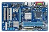
KB_MS ATX_12V LGA775 CPU_FAN COMA LPT LAN Coaxial R_USB30 ATX IDE DDR3_1 GA-P41T-USB3L DDR3_2 USB AUDIO F_AUDIO NEC D720200F1 RTL8111D IT8718 PCIEX16 PCIEX1_1 CODEC PCIEX1_2 CD_IN PCI1 SPDIF_O PCI2 PCI3 Intel® G41 SYS_FAN1 BAT F_PANEL Intel® ICH7 PWR_FAN CLR_CMOS F_USB1 - Gigabyte GA-P41T-USB3L | Manual - Page 8
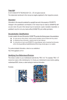
GA-P41T-USB3L Block Diagram PCIe CLK (100 MHz) 1 PCI Express x16 x16 PCI Express x16 2 USB 3.0 LAN NEC D720200F1 x1 RJ45 RTL8111D x1 PCI Express Bus x1 x1 PCIe CLK (100 MHz) 2 PCI Express x1 PCI Bus LGA775 CPU CPU CLK+/(333/266/200 MHz) Host Interface Intel® G41 DDR3 1333 (O.C.)/1066/ - Gigabyte GA-P41T-USB3L | Manual - Page 9
electrostatic discharge (ESD). Prior to installation, carefully read the user's manual and follow these procedures: • Prior to installation, do not remove you are uncertain about any installation steps or have a problem related to the use of the product, please consult a certified computer technician. - Gigabyte GA-P41T-USB3L | Manual - Page 10
w North Bridge: Intel® G41 Express Chipset w South Bridge: Intel® ICH7 2 x 1.5V DDR3 DIMM sockets supporting up to 4 GB of system memory (Note 1) w Dual channel memory architecture w Support for DDR3 1333 (O.C.)/1066/800 MHz memory modules (Go to GIGABYTE's website for the latest - Gigabyte GA-P41T-USB3L | Manual - Page 11
w Back Panel w Connectors w w w w w w I/O w Hardware Monitor w w w w w w 1 x 24-pin ATX main power connector 1 x 4-pin ATX 12V power connector 1 x floppy disk drive connector 1 x IDE connector 4 x SATA 3Gb/s connectors 1 x CPU fan - Gigabyte GA-P41T-USB3L | Manual - Page 12
Use of licensed AWARD BIOS Support for DualBIOS™ PnP 1.0a, DMI 2.0, SM BIOS 2.4, ACPI 1.0b Support for @BIOS Support for Q-Flash Support for Xpress BIOS Rescue Support for Download Center Support for Xpress Install Support for Xpress Recovery2 Support for EasyTune (Note 5) Support for Easy Energy - Gigabyte GA-P41T-USB3L | Manual - Page 13
and CPU Cooler Read the following guidelines before you begin to install the CPU: • Make sure that the motherboard supports the CPU. (Go to GIGABYTE's website for the latest CPU support list.) • Always turn off the computer and unplug the power cord from the power outlet before installing the CPU - Gigabyte GA-P41T-USB3L | Manual - Page 14
B. Follow the steps below to correctly install the CPU into the motherboard CPU socket. Before installing the CPU, make sure to turn off the computer and unplug the power cord from the power outlet to prevent damage to the CPU. CPU Socket Lever Step 1: Completely raise the CPU socket lever. Step - Gigabyte GA-P41T-USB3L | Manual - Page 15
" when pushing down each push pin. Check that the Male and Female push pins are joined closely. (Refer to your CPU cooler installation manual for instructions on installing the cooler.) Step 5: After the installation, check the back of the motherboard. If the push pin is inserted as the picture - Gigabyte GA-P41T-USB3L | Manual - Page 16
capacity, brand, speed, and chips be used. (Go to GIGABYTE's website for the latest memory support list.) • Always turn off the computer and unplug the power DDR3 memory sockets and supports Dual Channel Technology. After the memory is installed, the BIOS will automatically detect the - Gigabyte GA-P41T-USB3L | Manual - Page 17
1-4-2 Installing a Memory Before installing a memory module, make sure to turn off the computer and unplug the power cord from the power outlet to prevent damage to the memory module. DDR3 and DDR2 DIMMs are not compatible to each other or DDR DIMMs. Be sure to install DDR3 DIMMs on this motherboard - Gigabyte GA-P41T-USB3L | Manual - Page 18
an expansion card: • Make sure the motherboard supports the expansion card. Carefully read the manual that came with your expansion card. • Always . If necessary, go to BIOS Setup to make any required BIOS changes for your expansion card(s). 7. Install the driver provided with the expansion card - Gigabyte GA-P41T-USB3L | Manual - Page 19
State Description Blinking Data transmission or receiving is occurring Off No data transmission or receiving is occurring USB 2.0/1.1 Port The USB port supports the USB 2.0/1.1 specification. Use this port for USB devices such as a USB keyboard/mouse, USB printer, USB flash drive and etc. • When - Gigabyte GA-P41T-USB3L | Manual - Page 20
channel audio, you have to use an HD front panel audio module and enable the multi-channel audio feature through the audio driver. Refer to the instructions on setting up a 2/4/5.1/7.1-channel audio configuration in Chapter 5, "Configuring 2/4/5.1/7.1-Channel Audio." Hardware Installation - 20 - - Gigabyte GA-P41T-USB3L | Manual - Page 21
1-7 Internal Connectors 1 3 10 4 15 11 12 1) ATX_12V 2) ATX 3) CPU_FAN 4) SYS_FAN1/2 5) PWR_FAN 6) FDD 7) IDE 8) SATA2_0/1/2/3 7 2 9 14 5 8 6 13 4 9) F_PANEL 10) F_AUDIO 11) CD_IN 12) SPDIF_O 13) F_USB1/F_USB2 14) CLR_CMOS 15) BAT Read the following - Gigabyte GA-P41T-USB3L | Manual - Page 22
power, the result can lead to an unstable or unbootable system. 3 4 1 2 ATX_12V ATX_12V: Pin No. 1 2 3 4 Definition GND GND +12V +12V 12 24 1 13 ATX ATX: Pin No. 1 2 3 4 5 6 7 8 9 10 11 12 Definition Pin No. 3.3V 13 3.3V 14 GND 15 +5V 16 GND 17 +5V 18 GND 19 Power - Gigabyte GA-P41T-USB3L | Manual - Page 23
FDD (Floppy Disk Drive Connector) This connector is used to connect a floppy disk drive. The types of floppy disk drives supported are: 360 KB, 720 KB, 1.2 MB, 1.44 MB, and 2.88 MB. Before connecting a floppy disk drive, be sure to locate pin 1 of the connector and the floppy disk drive cable. The - Gigabyte GA-P41T-USB3L | Manual - Page 24
configuring master/slave settings for the IDE devices, read the instructions from the device manufacturers.) 40 39 2 1 8) SATA2_0 3Gb/s standard and are compatible with SATA 1.5Gb/s standard. Each SATA connector supports a single SATA device. SATA2_3 7 1 SATA2_2 7 1 SATA2_1 7 1 SATA2_0 - Gigabyte GA-P41T-USB3L | Manual - Page 25
a beep code. One single short beep will be heard if no problem is detected at system startup. If a problem is detected, the BIOS may issue beeps in different patterns to indicate the problem. Refer to Chapter 5, "Troubleshooting," for information about beep codes. • HD (Hard Drive Activity LED, Blue - Gigabyte GA-P41T-USB3L | Manual - Page 26
8 No Pin 8 No Pin 9 LINE2_L 9 Line Out (L) 10 GND 10 NC • The front panel audio header supports HD audio by default. If your chassis provides an AC'97 front panel audio module, refer to the instructions on how to activate AC'97 functionality via the audio software in Chapter 5, "Configuring - Gigabyte GA-P41T-USB3L | Manual - Page 27
12) SPDIF_O (S/PDIF Out Header) This header supports digital S/PDIF Out and connects a S/PDIF digital audio at the same time. For information about connecting the S/PDIF digital audio cable, carefully read the manual for your expansion card. Pin No. Definition 1 1 SPDIFO 2 GND 13) F_USB1/F_USB2 - Gigabyte GA-P41T-USB3L | Manual - Page 28
may cause damage to the motherboard. • After system restart, go to BIOS Setup to load factory defaults (select Load Optimized Defaults) or manually configure the BIOS settings (refer to Chapter 2, "BIOS Setup," for BIOS configurations). 16) BAT (Battery) The battery provides power to keep the values - Gigabyte GA-P41T-USB3L | Manual - Page 29
from the Internet and updates the BIOS. For instructions on using the Q-Flash and @BIOS utilities, refer to Chapter 4, "BIOS Update Utilities." • Because BIOS flashing is potentially risky, if you do not encounter problems using the current version of BIOS, it is recommended that you not flash the - Gigabyte GA-P41T-USB3L | Manual - Page 30
, An Energy Star Ally Copyright (C) 1984-2009, Award Software, Inc. Motherboard Model BIOS Version P41T-USB3L F1a . . . . : BIOS Setup : XpressRecovery2 : Boot Menu : Qflash 12/29/2009-G41-ICH7-6A79PG0DC-00 Function Keys Function Keys Function Keys: : POST SCREEN Press - Gigabyte GA-P41T-USB3L | Manual - Page 31
and press to accept or enter a sub-menu. (Sample BIOS Version: F1a) CMOS Setup Utility-Copyright (C) 1984-2009 Award Software MB Intelligent Tweaker(M.I.T.) Standard CMOS Features Advanced BIOS Features Integrated Peripherals Power Management Setup PnP/PCI Configurations PC - Gigabyte GA-P41T-USB3L | Manual - Page 32
BIOS settings from a profile created before, without the hassles of reconfiguring the BIOS settings. First select the profile you wish to load, then press to complete. MB of errors that stop the system boot, etc. Advanced BIOS Features Use this menu to configure the device boot order, - Gigabyte GA-P41T-USB3L | Manual - Page 33
: General Help F7: Optimized Defaults CMOS Setup Utility-Copyright (C) 1984-2009 Award Software MB Intelligent Tweaker(M.I.T.) x CAS Latency Time 9 x tRCD 9 x tRP 9 x tRAS values.) (Note) This item appears only if you install a CPU that supports this feature. - 33 - BIOS Setup - Gigabyte GA-P41T-USB3L | Manual - Page 34
chip and memory. Auto allows the BIOS to automatically set the R.G.B. mode based Disabled) CPU Host Frequency (Mhz) Allows you to manually set the CPU host frequency. The adjustable range is . PCI Express Frequency (Mhz) Allows you to manually set the PCIe clock frequency. The adjustable range is - Gigabyte GA-P41T-USB3L | Manual - Page 35
control items below to be configurable. Options are: Auto (default), Manual. >>>>> Standard Timing Control CAS Latency Time Options are: Auto (default), 4~11. tRCD Options are: Auto (default), 1~15. tRP Options are: Auto (default), 1~15. tRAS Options are: Auto (default), 1~63. - 35 - BIOS Setup - Gigabyte GA-P41T-USB3L | Manual - Page 36
are: Auto (default), 1~255. tRTP Options are: Auto (default), 1~15. Command Rate(CMD) Options are: Auto (default), 1~3. ESC: Exit F1: General Help F7: Optimized Defaults BIOS Setup - 36 - - Gigabyte GA-P41T-USB3L | Manual - Page 37
Options are: Auto (default), +800ps~-700ps. DIMM2 Clock Skew Control Options are: Auto (default), +800ps~-700ps. ESC: Exit F1: General Help F7: Optimized Defaults - 37 - BIOS Setup - Gigabyte GA-P41T-USB3L | Manual - Page 38
DDR Write Leveling Allows you to determine whether to fine-tune memory parameters to enhance memory compatibility. Auto Lets the BIOS decide whether to enable this function. (Default) Enabled Enables this function to enhance memory compatibility. Disabled Disables this function. DDR Write Training - Gigabyte GA-P41T-USB3L | Manual - Page 39
The default is Auto. >>> MCH/ICH MCH Core The default is Auto. ICH I/O The default is Auto. >>> DRAM DRAM Voltage The default is Auto. - 39 - BIOS Setup - Gigabyte GA-P41T-USB3L | Manual - Page 40
[None] Drive A Floppy 3 Mode Support [1.44M, 3.5"] [Disabled] Halt On [ the three methods below: • Auto Lets the BIOS automatically detect IDE/SATA devices during the POST. for faster system startup. • Manual Allows you to manually enter the specifications of the hard - Gigabyte GA-P41T-USB3L | Manual - Page 41
25", 1.2M/5.25", 720K/3.5", 1.44M/3.5", 2.88M/3.5". Floppy 3 Mode Support Allows you to specify whether the installed floppy disk drive is 3-mode system will stop for an error during the POST. All Errors Whenever the BIOS detects a non-fatal error the system boot will stop. No Errors The - Gigabyte GA-P41T-USB3L | Manual - Page 42
(Note) C4/C4E State Support (Note) CPU Thermal Monitor 2(TM2) (Note) CPU EIST Function (Note) Virtualization Technology (Note) Delay For HDD (Secs) Full Screen LOGO Show Backup BIOS Image to HDD Init Display First [Press Enter] [Disabled] [Floppy] [Hard Disk] [CDROM] [Setup - Gigabyte GA-P41T-USB3L | Manual - Page 43
supports multi-core technology. This feature only works for operating systems that support with its supporting software and Enabled) C2/C2E State Support (Note) Allows you to Disabled) C4/C4E State Support (Note) Allows you to if the C2/C2E State Support option is enabled. ( CPU that supports this feature - Gigabyte GA-P41T-USB3L | Manual - Page 44
Show Allows you to determine whether to display the GIGABYTE Logo at system startup. Disabled displays normal POST message. (Default: Enabled) Backup BIOS Image to HDD Allows the system to copy the BIOS image file to the hard drive. If the system BIOS is corrupted, it will be recovered from this - Gigabyte GA-P41T-USB3L | Manual - Page 45
Controller USB 2.0 Controller USB Keyboard Support USB Mouse Support USB Storage Function [Enabled] [ SATA controller. Auto Lets the BIOS set SATA devices to Combined or automatically configured to Combined mode, you can manually re-configure it to Enhanced mode as - Gigabyte GA-P41T-USB3L | Manual - Page 46
Length fields show 0m, as shown in the figure above. When LAN Cable Is Functioning Normally... If no cable problem is detected on the LAN cable connected to a Gigabit hub or a 10/100 Mbps hub, the following message 1000 Mbps in Windows mode or when the LAN Boot ROM is activated. BIOS Setup - 46 - - Gigabyte GA-P41T-USB3L | Manual - Page 47
When a Cable Problem Occurs... If a cable problem occurs on a specified pair of wires, the Status field will show Short and then length shown will be the whether to detect USB storage devices, including USB flash drives and USB hard drives during the POST. (Default: Enabled) - 47 - BIOS Setup - Gigabyte GA-P41T-USB3L | Manual - Page 48
from a PCI or PCIe device. Note: To use this function, you need an ATX power supply providing at least 1A on the +5VSB lead. (Default: Enabled) Power signal from a modem that supports wake-up function. (Default: Enabled) (Note) Supported on Windows 7/Vista operating system only. BIOS Setup - 48 - - Gigabyte GA-P41T-USB3L | Manual - Page 49
effective. HPET Support (Note) Enables only if the HPET Support is set to Enabled. function, you need an ATX power supply providing at least Note: you need an ATX power supply providing at least AC power. EuP Support Determines whether to let Supported on Windows 7/Vista operating system only. - 49 - Gigabyte GA-P41T-USB3L | Manual - Page 50
Assignment Auto 3,4,5,7,9,10,11,12,14,15 PCI2 IRQ Assignment Auto 3,4,5,7,9,10,11,12,14,15 PCI3 IRQ Assignment Auto 3,4,5,7,9,10,11,12,14,15 BIOS auto-assigns IRQ to the first PCI slot. (Default) Assigns IRQ 3,4,5,7,9,10,11,12,14,15 to the first PCI slot - Gigabyte GA-P41T-USB3L | Manual - Page 51
or fan connection when this occurs. (Default: Disabled) CPU Smart FAN Control Enables or disables the CPU fan speed control function. Auto lets the BIOS decide whether to enable this function. Enabled allows the CPU fan to run at different speed according to the CPU temperature. You can adjust the - Gigabyte GA-P41T-USB3L | Manual - Page 52
try to load Fail-Safe defaults, which are the safest and most stable BIOS settings for the motherboard. 2-11 Load Optimized Defaults CMOS Setup Utility-Copyright (C) 1984-2009 Award Software MB Intelligent Tweaker(M.I.T.) Load Fail-Safe Defaults Standard CMOS Features Load Optimized - Gigabyte GA-P41T-USB3L | Manual - Page 53
2-12 Set Supervisor/User Password CMOS Setup Utility-Copyright (C) 1984-2009 Award Software MB Intelligent Tweaker(M.I.T.) Standard CMOS Features Advanced BIOS Features Integrated Peripherals Power Management Setup PnP/PCI Configurations Enter Password: PC Health Status Load Fail - Gigabyte GA-P41T-USB3L | Manual - Page 54
This saves the changes to the CMOS and exits the BIOS Setup program. Press or to return to the BIOS Setup Main Menu. 2-14 Exit Without Saving CMOS Setup Utility-Copyright (C) 1984-2009 Award Software MB Intelligent Tweaker(M.I.T.) Load Fail-Safe Defaults Standard CMOS Features - Gigabyte GA-P41T-USB3L | Manual - Page 55
recommended drivers. Or click Install Single Items to manually select the drivers instructions to restart your system. You can install other applications included in the motherboard driver disk. • For USB 2.0 driver support under the Windows XP operating system, please install the Windows XP Service - Gigabyte GA-P41T-USB3L | Manual - Page 56
applications that GIGABYTE develops and some free software. You can click the Install button on the right of an item to install it. 3-3 Technical Manuals This page provides GIGABYTE's application guides, content descriptions for this driver disk, and the motherboard manuals. Drivers Installation - Gigabyte GA-P41T-USB3L | Manual - Page 57
3-4 Contact For the detailed contact information of the GIGABYTE Taiwan headquarter or worldwide branch offices, click the URL on this page to link to the GIGABYTE website. 3-5 System This page provides the basic system information. - 57 - Drivers Installation - Gigabyte GA-P41T-USB3L | Manual - Page 58
, or applications, click the Download Center button to link to the GIGABYTE website. The latest version of the BIOS, drivers, or applications will be displayed. 3-7 New Utilities This page provides a quick link to GIGABYTE's lately developed utilities for users to install. You can click the Install - Gigabyte GA-P41T-USB3L | Manual - Page 59
up your system soon after the operating system and drivers are installed. • The amount of data and hard to restore it. System Requirements: • At least 512 MB of system memory • VESA compatible graphics card • Windows are not supported. • Hard drives in RAID/AHCI mode are not supported. Installation and - Gigabyte GA-P41T-USB3L | Manual - Page 60
note that if there is no enough unallocated space, Xpress Recovery2 cannot save the backup file. B. Accessing Xpress Recovery2 1. Boot from the motherboard driver disk to access Xpress Recovery2 for the first time. When you see the following message: Press any key to startup Xpress Recovery2, press - Gigabyte GA-P41T-USB3L | Manual - Page 61
D. Using the Restore Function in Xpress Recovery2 Select RESTORE to restore the backup to your hard drive in case the system breaks down. The RESTORE option will not be present if no backup is created before. E. Removing the Backup Step 1: If you wish to remove the backup file, select REMOVE. Step - Gigabyte GA-P41T-USB3L | Manual - Page 62
POST to access Q-Flash. Award Modular BIOS v6.00PG, An Energy Star Ally Copyright (C) 1984-2009, Award Software, Inc. P41T-USB3L F1a . . . . : BIOS Setup : XpressRecovery2 : Boot Menu : Qflash 12/29/2009-G41-ICH7-6A79PG0DC-00 Because BIOS flashing is potentially risky, please do - Gigabyte GA-P41T-USB3L | Manual - Page 63
and press . • The Save Main BIOS to Drive option allows you to save the current BIOS file. • Q-Flash only supports USB flash drive or hard drives using FAT32/16/12 file system. • If the BIOS update file is saved to a hard drive in RAID/AHCI mode or a hard drive attached to an independent - Gigabyte GA-P41T-USB3L | Manual - Page 64
defaults. System will re-detect all peripheral devices after a BIOS update, so we recommend that you reload BIOS defaults. CMOS Setup Utility-Copyright (C) 1984-2009 Award Software MB Intelligent Tweaker(M.I.T.) Load Fail-Safe Defaults Standard CMOS Features Load Optimized Defaults - Gigabyte GA-P41T-USB3L | Manual - Page 65
your motherboard is not present on the @BIOS server site, please manually download the BIOS update file from GIGABYTE's website and follow the instructions in "Update the BIOS without Using the Internet Update Function" below. 2. Update the BIOS without Using the Internet Update Function: Click - Gigabyte GA-P41T-USB3L | Manual - Page 66
4-3 EasyTune 6 GIGABYTE's EasyTune 6 is a simple and easy-to-use interface that allows model. Grayed-out area(s) indicates that the item is not configurable or the function is not supported. Incorrectly doing overclock/overvoltage may result in damage to the hardware components such as CPU, chipset - Gigabyte GA-P41T-USB3L | Manual - Page 67
sacrificing computing performance. The Easy Energy Saver Interface A. Meter Mode In Meter Mode, GIGABYTE Easy Energy Saver shows how much power they have saved in a set period of time Power Scores are for reference only. Actual results may vary based on testing method. - 67 - Unique Features - Gigabyte GA-P41T-USB3L | Manual - Page 68
Duo/ Pentium Dual-Core/ Celeron Dual-Core/ Celeron 400 Series CPU to enable support for Easy Energy Saver. Before using the Easy Energy Saver function, make sure the CPU Enhanced Halt (C1E) and CPU EIST Function items in the BIOS Setup program are set to Enabled. (Note 2) Maximize system power - Gigabyte GA-P41T-USB3L | Manual - Page 69
on the same network, making full use of Internet resources. Directions for using Q-Share After installing Q-Share from the motherboard driver disk, go to Start>All Programs>GIGABYTE>Q-Share. exe to launch the Q-Share tool. Find the Q-Share icon to configure the data sharing settings. in the - Gigabyte GA-P41T-USB3L | Manual - Page 70
up to 64 backups (the actual limit depends on the size of each partition). When this limit is reached, the oldest backup will be ovewritten. Instructions for copying files/folders from a backup: To browse through your backups made at different time, select a backup time using the time scroll bar on - Gigabyte GA-P41T-USB3L | Manual - Page 71
jack and manually configure the jack for microphone functionality. • Audio signals will be present on both of the front and back panel audio connections simultaneously. If you want to mute the back panel audio (only supported when using an HD front panel audio module), refer to instructions on page - Gigabyte GA-P41T-USB3L | Manual - Page 72
The pictures to the right show the 7.1-channel speaker configurations. 7.1-Channel Speakers: Front Speaker Out Rear Speaker Out Center/Subwoofer Speaker Out Side Speaker Out Step 2: Connect an audio device to an audio jack. The The current connected device is dialog box appears. Select the - Gigabyte GA-P41T-USB3L | Manual - Page 73
C. Activating an AC'97 Front Panel Audio Module If your chassis provides an AC'97 front panel audio module, to activate the AC'97 functionality, click the tool icon on the Speaker Configuration tab. On the Connector Settings dialog box, select the Disable front panel jack detection check box. Click - Gigabyte GA-P41T-USB3L | Manual - Page 74
5-1-2 Configuring S/PDIF Out Configuring S/PDIF Out: The S/PDIF Out jacks can transmit audio signals to an external decoder for decoding to get the best audio quality. To output S/PDIF digital audio signals to an external decoder, connect a S/PDIF coaxial cable to the coxial S/PDIF out connector on - Gigabyte GA-P41T-USB3L | Manual - Page 75
5-1-3 Configuring Microphone Recording Step 1: After installing the audio driver, the HD Audio Manager icon will appear in the notification area. Double-click the icon to access the HD Audio Manager. Step 2: Connect your microphone - Gigabyte GA-P41T-USB3L | Manual - Page 76
Step 4: To raise the recording and playback volume for the microphone, click the Microphone Boost icon on the right of the Recording Volume slider and set the Microphone Boost level. Step 5: After completing the settings above, click Start, point to All Programs, point to Accessories, and then click - Gigabyte GA-P41T-USB3L | Manual - Page 77
. Be sure to save the recorded audio file upon completion. B. Playing the Recorded Sound You can play your recording in a digital media player program that supports your audio file format. - 77 - Appendix - Gigabyte GA-P41T-USB3L | Manual - Page 78
5-2 Troubleshooting 5-2-1 Frequently Asked Questions To read more FAQs for your motherboard, please go to the Support&Downloads\Motherboard\FAQ page on GIGABYTE's website. Q: In the BIOS Setup program, why are some BIOS options missing? A: Some advanced options are hidden in the BIOS Setup program - Gigabyte GA-P41T-USB3L | Manual - Page 79
If you encounter any troubles during system startup, follow the troubleshooting procedure below to solve the problem. START Turn off the the memory into the memory socket. Yes The problem is verified and solved. Insert the graphics card. Connect the ATX main power cable and the 12V power cable. - Gigabyte GA-P41T-USB3L | Manual - Page 80
"Save & Exit Setup" to save changes and exit BIOS Setup. The problem is verified and solved. Turn off the computer and connect problem, contact the place of purchase or local dealer for help. Or go to the Support&Downloads\Technical Service Zone page to submit your question. Our customer service - Gigabyte GA-P41T-USB3L | Manual - Page 81
" product. Restriction of Hazardous Substances (RoHS) Directive Statement GIGABYTE products have not intended to add and safe from hazardous government office, your household waste disposal service or where you purchased the product manual and we will be glad to help you with your effort. - Gigabyte GA-P41T-USB3L | Manual - Page 82
Finally, we suggest that you practice other environmentally friendly actions by understanding and using the energy-saving features of this product (where applicable), recycling the inner and outer packaging (including shipping containers) this product was delivered in, and by disposing of or - Gigabyte GA-P41T-USB3L | Manual - Page 83
- 83 - Appendix - Gigabyte GA-P41T-USB3L | Manual - Page 84
Appendix - 84 - - Gigabyte GA-P41T-USB3L | Manual - Page 85
- 85 - Appendix - Gigabyte GA-P41T-USB3L | Manual - Page 86
Appendix - 86 - - Gigabyte GA-P41T-USB3L | Manual - Page 87
231, Taiwan TEL: +886-2-8912-4000 FAX: +886-2-8912-4003 Tech. and Non-Tech. Support (Sales/Marketing) : http://ggts.gigabyte.com.tw WEB address (English): http://www.gigabyte.com.tw WEB address (Chinese): http://www.gigabyte.tw • G.B.T. INC. - U.S.A. TEL: +1-626-854-9338 FAX: +1-626-854-9339 Tech - Gigabyte GA-P41T-USB3L | Manual - Page 88
website, select your language in the language list on the top right corner of the website. • GIGABYTE Global Service System To submit a technical or non-technical (Sales/Marketing) question, please link to: http://ggts.gigabyte.com.tw Then select your language to enter the system. Appendix - 88 -
-
 1
1 -
 2
2 -
 3
3 -
 4
4 -
 5
5 -
 6
6 -
 7
7 -
8
-
9
-
10
-
11
-
12
-
13
-
14
-
15
-
16
-
17
-
18
-
19
-
20
-
21
-
22
-
23
-
24
-
25
-
26
-
27
-
28
-
29
-
30
-
31
-
32
-
33
-
34
-
35
-
36
-
37
-
38
-
39
-
40
-
41
-
42
-
43
-
44
-
45
-
46
-
47
-
48
-
49
-
50
-
51
-
52
-
53
-
54
-
55
-
56
-
57
-
58
-
59
-
60
-
61
-
62
-
63
-
64
-
65
-
66
-
67
-
68
-
69
-
70
-
71
-
72
-
73
-
74
-
75
-
76
-
77
-
78
-
79
-
80
-
81
-
82
-
83
-
84
-
85
-
86
-
87
-
88
 |
 |

GA-P41T-USB3L
LGA775 socket motherboard for Intel
®
Core
™
processor family/
Intel
®
Pentium
®
processor family/Intel
®
Celeron
®
processor family
User's Manual
Rev. 1001
12ME-P41TB3L-1001R