Gigabyte GA-P55-UD3 Manual
Gigabyte GA-P55-UD3 Manual
 |
View all Gigabyte GA-P55-UD3 manuals
Add to My Manuals
Save this manual to your list of manuals |
Gigabyte GA-P55-UD3 manual content summary:
- Gigabyte GA-P55-UD3 | Manual - Page 1
GA-P55-UD3 LGA1156 socket motherboard for Intel® Core™ i7 processor family/ Intel® Core™ i5 processor family User's Manual Rev. 1001 12ME-P55UD3-1001R - Gigabyte GA-P55-UD3 | Manual - Page 2
Motherboard GA-P55-UD3 Jul. 20, 2009 Motherboard GA-P55-UD3 Jul. 20, 2009 - Gigabyte GA-P55-UD3 | Manual - Page 3
read the User's Manual. For instructions on how to use GIGABYTE's unique features, read or download the information on/from the Support&Downloads\Motherboard\Technology Guide page on our website. For product-related information, check on our website at: http://www.gigabyte.com.tw Identifying Your - Gigabyte GA-P55-UD3 | Manual - Page 4
Items...6 GA-P55-UD3 Motherboard Layout 7 Block Diagram...8 Chapter 1 Hardware Installation 9 1-1 Installation Precautions 9 1-2 Product Specifications 10 1-3 Installing the CPU and CPU Cooler 13 1-3-1 Installing the CPU 13 1-3-2 Installing the CPU Cooler 15 1-4 Installing the Memory 16 - Gigabyte GA-P55-UD3 | Manual - Page 5
61 3-1 Installing Chipset Drivers 61 3-2 Application Software 62 3-3 Technical Manuals 62 3-4 Contact...63 3-5 System...63 3-6 Download Center 64 3-7 New Utilities...64 Chapter 4 Unique Features 65 4-1 Xpress Recovery2 65 4-2 BIOS Update Utilities 68 4-2-1 Updating the BIOS with the Q-Flash - Gigabyte GA-P55-UD3 | Manual - Page 6
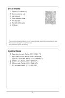
Box Contents GA-P55-UD3 motherboard Motherboard driver disk User's Manual Quick Installation Guide One IDE cable Two SATA 3Gb/s cables I/O Shield • The box contents above are for reference only and the actual items shall depend on the product - Gigabyte GA-P55-UD3 | Manual - Page 7
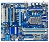
GA-P55-UD3 Motherboard Layout KB_USB R_SPDIF R_USB_3 R_USB_2 CPU_FAN ATX_12V_2X4 R_USB_1 USB_LAN SYS_FAN1 AUDIO F_AUDIO RTL8111D PCIEX16 PCIEX1_1 PCIEX1_2 CD_IN SPDIF_I SPDIF_O CODEC PCI1 PCIEX4 PCI2 IT8720 PCI3 LPT COMA LGA1156 PHASE LED ATX PWR_FAN GA-P55-UD3 DDR3_2 DDR3_1 - Gigabyte GA-P55-UD3 | Manual - Page 8
PCI Express x1 2 SATA 3Gb/s ATA-133/100/66/33 IDE Channel PCI Bus GIGABYTE SATA2 DMI Interface 1 PCI Express x4 x4 PCI Express Bus Intel® P55 Dual BIOS 6 SATA 3Gb/s 14 USB Ports LPC Bus IT8720 Floppy COM Port LPT CODEC PS/2 KB/Mouse Surround Speaker Out Center/Subwoofer Speaker Out Side - Gigabyte GA-P55-UD3 | Manual - Page 9
manual and follow these procedures: • Prior to installation, do not remove or break motherboard S/N (ESD) wrist strap when handling electronic com- ponents such as a motherboard, CPU or memory. If you do not have an ESD steps or have a problem related to the use of the product, please consult - Gigabyte GA-P55-UD3 | Manual - Page 10
® Core™ i7 series processor/Intel® Core™ i5 series processor in the LGA1156 package (Go to GIGABYTE's website for the latest CPU support list.) L3 cache varies with CPU Chipset Intel® P55 Express Chipset Memory Audio 4 x 1.5V DDR3 DIMM sockets supporting up to 16 GB of system - Gigabyte GA-P55-UD3 | Manual - Page 11
optical S/PDIF Out connector 10 x USB 2.0/1.1 ports 1 x RJ-45 port 6 x audio jacks (Center/Subwoofer Speaker Out/Rear Speaker Out/ Side Speaker Out/Line In/Line Out/Microphone Use of licensed AWARD BIOS Support for DualBIOS™ PnP 1.0a, DMI 2.0, SM BIOS 2.4, ACPI 1.0b - 11 - Hardware Installation - Gigabyte GA-P55-UD3 | Manual - Page 12
w w Bundled Software w Support for @BIOS Support for Q-Flash Support for Xpress BIOS Rescue Support for Download Center Support for Xpress Install Support for Xpress Recovery2 Support for EasyTune (Note 5) Support for Dynamic Energy Saver™ 2 Support for Smart 6™ Support for Q-Share Norton - Gigabyte GA-P55-UD3 | Manual - Page 13
set the frequency beyond the standard specifications, please do so according to your hardware specifications including the CPU, graphics card, memory, hard drive, etc. 1-3-1 Installing the CPU A. Locate the alignment keys on the motherboard CPU socket and the notches on the CPU. LGA1156 CPU Socket - Gigabyte GA-P55-UD3 | Manual - Page 14
B. Follow the steps below to correctly install the CPU into the motherboard CPU socket. Before installing the CPU, make sure to turn off the computer and unplug the power cord from the power outlet to prevent damage to the CPU. Step 1: Gently press the CPU socket lever handle down and away from the - Gigabyte GA-P55-UD3 | Manual - Page 15
CPU cooler installation manual for instructions on installing the cooler.) Step 5: After the installation, check the back of the motherboard. If the push the CPU cooler to the CPU fan header (CPU_FAN) on the motherboard. Use extreme care when removing the CPU cooler because the thermal grease/tape - Gigabyte GA-P55-UD3 | Manual - Page 16
. If you are unable to insert the memory, switch the direction. 1-4-1 Dual Channel Memory Configuration This motherboard provides four DDR3 memory sockets and supports Dual Channel Technology. After the memory is installed, the BIOS will automatically detect the specifications and capacity of - Gigabyte GA-P55-UD3 | Manual - Page 17
to install DDR3 DIMMs on this motherboard. Notch DDR3 DIMM A DDR3 memory module has a notch, so it can only fit in one direction. Follow the steps below to correctly install your memory modules in the memory sockets. Step 1: Note the orientation of the memory module. Spread the retaining clips at - Gigabyte GA-P55-UD3 | Manual - Page 18
an expansion card: • Make sure the motherboard supports the expansion card. Carefully read the manual that came with your expansion card. • Always If necessary, go to BIOS Setup to make any required BIOS changes for your expansion card(s). 7. Install the driver provided with the expansion card - Gigabyte GA-P55-UD3 | Manual - Page 19
that supports digital coaxial audio. Before using this feature, ensure that your audio system provides a coaxial digital audio in connector. RJ-45 LAN Port The Gigabit Ethernet LAN port provides Internet connection at up to 1 Gbps data rate. The following describes the states of the LAN port LEDs - Gigabyte GA-P55-UD3 | Manual - Page 20
to the default speakers settings, the ~ audio jacks can be reconfigured to perform different functions via the audio software. Only microphones still MUST be connected to the default Mic in jack ( ). Refer to the instructions on setting up a 2/4/5.1/7.1-channel audio configuration in Chapter - Gigabyte GA-P55-UD3 | Manual - Page 21
devices. • After installing the device and before turning on the computer, make sure the device cable has been securely attached to the connector on the motherboard. - 21 - Hardware Installation - Gigabyte GA-P55-UD3 | Manual - Page 22
can supply enough stable power to all the components on the motherboard. Before connecting the power connector, first make sure the power 12V power connector is recommended by the CPU manufacturer when using an Intel Extreme Edition CPU (130W). • To meet expansion requirements, it is recommended - Gigabyte GA-P55-UD3 | Manual - Page 23
correct orientation (the black connector wire is the ground wire). The motherboard supports CPU fan speed control, which requires the use of a CPU disk drive. The types of floppy disk drives supported are: 360 KB, 720 KB, 1.2 MB, 1.44 MB, and 2.88 MB. Before connecting a floppy disk drive, be sure - Gigabyte GA-P55-UD3 | Manual - Page 24
compatible with SATA 1.5Gb/s standard. Each SATA connector supports a single SATA device. The P55 Chipset supports RAID 0, RAID 1, RAID 5, and RAID 10. Refer to Chapter 5, "Configuring SATA Hard Drive(s)," for instructions on configuring a RAID array. 7 SATA2_3 SATA2_4 SATA2_5 1 Pin No. SATA2_0 - Gigabyte GA-P55-UD3 | Manual - Page 25
are compatible with SATA 1.5Gb/s standard. Each SATA connector supports a single SATA device. The GIGABYTE SATA2 controller supports RAID 0, RAID 1, and JBOD. Refer to Chapter 5, "Configuring SATA Hard Drive(s)," for instructions on configuring a RAID array. GSATA2_1 7 1 7 1 GSATA2_0 Pin No - Gigabyte GA-P55-UD3 | Manual - Page 26
beep will be heard if no problem is detected at system startup. If a problem is detected, the BIOS may issue beeps in different patterns to indicate the problem. Refer to Chapter 5, "Troubleshooting," for information about beep codes. • HD (Hard Drive Activity LED, Blue) Connects to the hard drive - Gigabyte GA-P55-UD3 | Manual - Page 27
NC • The front panel audio header supports HD audio by default. If your chassis provides an AC'97 front panel audio module, refer to the instructions on how to activate AC'97 functionality via the audio software in Chapter 5, "Configuring 2/4/5.1/7.1-Channel Audio." • Audio signals will be present - Gigabyte GA-P55-UD3 | Manual - Page 28
No. Definition 1 Power 2 SPDIFI 3 GND 1 15) SPDIF_O (S/PDIF Out Header) This header supports digital S/PDIF Out and connects a S/PDIF digital audio cable (provided by expansion cards) for digital audio output from your motherboard to certain expansion cards like graphics cards and sound cards. For - Gigabyte GA-P55-UD3 | Manual - Page 29
16) F_USB1/F_USB2 (USB Headers, Blue) The headers conform to USB 2.0/1.1 specification. Each USB header can provide two USB ports via an optional USB bracket. For purchasing the optional USB bracket, please contact the local dealer. Pin No. Definition 1 Power (5V) 9 1 2 Power (5V) 10 2 3 USB - Gigabyte GA-P55-UD3 | Manual - Page 30
serial port via an optional COM port cable. For purchasing the optional COM port cable, please contact motherboard. • After system restart, go to BIOS Setup to load factory defaults (select Load Optimized Defaults) or manually configure the BIOS settings (refer to Chapter 2, "BIOS Setup," for BIOS - Gigabyte GA-P55-UD3 | Manual - Page 31
20) PHASE LED The number of lighted LEDs indicates the CPU loading. The higher the CPU loading, the more the number of lighted LEDs. To enable the Phase LED display function, please first enable Dynamic Energy Saver™ 2. Refer to Chapter 4, "Dynamic Energy Saver™ 2," for more details. - 31 - - Gigabyte GA-P55-UD3 | Manual - Page 32
Hardware Installation - 32 - - Gigabyte GA-P55-UD3 | Manual - Page 33
that searches and downloads the latest version of BIOS from the Internet and updates the BIOS. For instructions on using the Q-Flash and @BIOS utilities, refer to Chapter 4, "BIOS Update Utilities." • Because BIOS flashing is potentially risky, if you do not encounter problems using the current - Gigabyte GA-P55-UD3 | Manual - Page 34
v6.00PG, An Energy Star Ally Copyright (C) 1984-2009, Award Software, Inc. Motherboard Model BIOS Version P55-UD3 D13c . . . . : BIOS Setup : XpressRecovery2 : Boot Menu : Qflash 07/13/2009-P55-7A89RG0KC-00 Function Keys Function Keys Function Keys: : POST SCREEN Press - Gigabyte GA-P55-UD3 | Manual - Page 35
> Move cursor to the Item Help block on the right (submenus only) Restore the previous BIOS settings for the current submenus Load the Fail-Safe BIOS default settings for the current submenus Load the Optimized BIOS default settings for the current submenus Access - Gigabyte GA-P55-UD3 | Manual - Page 36
before, without the hassles of reconfiguring the BIOS settings. First select the profile you wish to load, then press to complete. MB Intelligent Tweaker(M.I.T.) Use this menu to configure the clock, frequency and voltages of your CPU, memory, etc. Standard CMOS Features Use this - Gigabyte GA-P55-UD3 | Manual - Page 37
Software MB Intelligent Tweaker(M.I.T.) } M.I.T Current Status } Advanced Frequency Settings } Advanced Memory Settings } Advanced Voltage Settings } Miscellaneous Settings [Press Enter] [Press Enter] [Press Enter] [Press Enter] [Press Enter] Item Help Menu Level BIOS Version - Gigabyte GA-P55-UD3 | Manual - Page 38
PD: Value F10: Save F6: Fail-Safe Defaults ESC: Exit F1: General Help F7: Optimized Defaults Intel(R) Turbo Boost Tech. Allows you to determine whether the BIOS automatically configure this setting. (Default: Auto) (Note) This item is present only if you install a CPU that supports this - Gigabyte GA-P55-UD3 | Manual - Page 39
is a more enhanced power-saving state than C1. Auto lets the BIOS automatically configure this setting. (Default: Auto) CPU Thermal Monitor (Note) Enables or disables is present only if you install a CPU that supports this feature. For more information about Intel CPUs' unique features, please visit Intel - Gigabyte GA-P55-UD3 | Manual - Page 40
It is highly recommended that the CPU frequency be set in accordance with the CPU specifications. Extreme Memory Profile (X.M.P.) (Note) Allows the BIOS to read the SPD data on XMP memory module(s) to enhance memory performance when enabled. Disabled Disables this function. (Default) Profile1 - Gigabyte GA-P55-UD3 | Manual - Page 41
: Exit F1: General Help F7: Optimized Defaults Extreme Memory Profile (X.M.P.) (Note) Allows the BIOS to read the SPD data on XMP memory module(s) to enhance memory performance when enabled. Disabled Disables this function. (Default) Profile1 Uses Profile 1 settings. Profile2 (Note) Uses - Gigabyte GA-P55-UD3 | Manual - Page 42
Extreme memory module or Extreme Memory Profile (X.M.P.) is set to Disabled, this item will display as 1.5V. When Extreme Memory Profile (X.M.P.) is set to Profile1 or Profile2, this item will display the value based on the SPD data on the XMP memory Help Help - Gigabyte GA-P55-UD3 | Manual - Page 43
Options are: Auto (default), 1~63. Command Rate(CMD) Options are: Auto (default), 1~3. >>>>> Channel A/B Misc Timing Control Round Trip Latency Options are: Auto (default), 1~255. - 43 - BIOS Setup - Gigabyte GA-P55-UD3 | Manual - Page 44
CMOS Setup Utility-Copyright (C) 1984-2009 Award Software Channel A Turnaround Settings >>>>> Channel A Reads Followed by Reads x Different DIMMs 6 x Different Ranks 5 x On Same Rank Options are: Auto (default), 1~2. ESC: Exit F1: General Help F7: Optimized Defaults BIOS Setup - 44 - - Gigabyte GA-P55-UD3 | Manual - Page 45
Address VRef. 0.750V [Auto] Ch-B Address VRef. 0.750V [Auto] Item Help Menu Level Move Enter: Select F5: Previous Values +/-/PU/PD: Value F10 more constant under light and heavy CPU load. Disabled sets the CPU voltage following Intel specifications. (Default: Disabled - BIOS Setup - Gigabyte GA-P55-UD3 | Manual - Page 46
Software MB Intelligent Tweaker(M.I.T.) } M.I.T Current Status } Advanced Frequency Settings } Advanced Memory Settings } Advanced Voltage Settings } Miscellaneous Settings [Press Enter] [Press Enter] [Press Enter] [Press Enter] [Press Enter] Item Help Menu Level BIOS Version - Gigabyte GA-P55-UD3 | Manual - Page 47
22:31:24 Item Help Menu Level On Base Memory Extended Memory [All, Memory 2048M Item Help Menu Level Move Enter: Select F5: Previous Values +/-/PU/PD: Value F10: Save F6: Fail-Safe Defaults ESC: Exit F1: General Help F7: Optimized Defaults Date (mm:dd:yy) Sets set - Gigabyte GA-P55-UD3 | Manual - Page 48
Lets the BIOS automatically detect IDE/SATA devices during the POST. (Default) • None If no IDE/SATA devices are used, set this item to None so the system will skip the detection of the device during the POST for faster system startup. • Manual Allows you to manually enter the - Gigabyte GA-P55-UD3 | Manual - Page 49
ESC: Exit F1: General Help F7: Optimized Defaults Hard Disk BIOS Setup. After configuring this item, set the password(s) under the Set Supervisor/User Password item in the BIOS Main Menu. Setup A password is only required for entering the BIOS that supports this feature. For more information - Gigabyte GA-P55-UD3 | Manual - Page 50
For HDD (Secs) Allows you to set a delay time for the BIOS to initialize the hard drive as the system boots up. The ad- justable range is from 0 to 15 seconds. (Default: 0) Full Screen LOGO Show Allows you to determine whether to display the GIGABYTE Logo at system startup. Disabled displays - Gigabyte GA-P55-UD3 | Manual - Page 51
Help F7: Optimized Defaults SATA RAID/AHCI Mode (Intel P55 Chipset) Enables or disables RAID for the SATA controllers integrated in the Intel P55 chipset with other device. Set this option to Disabled if you wish to install operating systems that do not support Native mode. (Default - Gigabyte GA-P55-UD3 | Manual - Page 52
a 3rd party add-in audio card instead of using the onboard audio, set this item to Disabled. Exit F1: General Help F7: Optimized Defaults This motherboard incorporates cable diagnostic feature When LAN Cable Is Functioning Normally... If no cable problem is detected on the LAN cable connected to a - Gigabyte GA-P55-UD3 | Manual - Page 53
Problem Occurs... If a cable problem occurs ) Onboard SATA/IDE Device (GIGABYTE SATA2, IDE and GSATA2_0/1 Connectors) Enables or disables the IDE driver to enable advanced Serial ATA features such as Native Command Queuing and hot plug. RAID/IDE Enables RAID +EPP. - 53 - BIOS Setup - Gigabyte GA-P55-UD3 | Manual - Page 54
[Disabled] Everyday 0 : 0 : 0 [Enabled] [32-bit mode] [Disabled] [Disabled] Enter [Soft-Off] Item Help Menu Level Move Enter: Select F5: Previous Values +/-/PU modem that supports wake-up function. (Default: Enabled) (Note) Supported on Windows Vista operating system only. BIOS Setup - 54 - - Gigabyte GA-P55-UD3 | Manual - Page 55
ss) Alarm: Set the time at bit mode when you install 32-bit Windows Vista; select 64-bit mode when you install 64-bit Windows Vista. This item is configurable only if the HPET Support is set to Enabled. (Default: 32-bit Password Set a password settings. Memory The system returns to its last known awake - Gigabyte GA-P55-UD3 | Manual - Page 56
-Safe Defaults ESC: Exit F1: General Help F7: Optimized Defaults Reset Case Open Status the chassis intrusion detection device attached to the motherboard CI header. If the system chassis cover is Sets the warning threshold for CPU temperature. When CPU temperature exceeds the threshold, BIOS - Gigabyte GA-P55-UD3 | Manual - Page 57
is configurable only if CPU Smart FAN Control is set to Enabled. Auto Lets the BIOS automatically detect the type of CPU fan installed and sets the optimal CPU fan control mode. (Default) Voltage Sets Voltage mode for a 3-pin CPU fan. PWM Sets PWM mode for a 4-pin CPU fan. Note: The Voltage - Gigabyte GA-P55-UD3 | Manual - Page 58
, which are the safest and most stable BIOS settings for the motherboard. 2-10 Load Optimized Defaults CMOS Setup Utility-Copyright (C) 1984-2009 Award Software MB Intelligent Tweaker(M.I.T.) Standard CMOS Features Advanced BIOS Features Integrated Peripherals Power Management Setup PC - Gigabyte GA-P55-UD3 | Manual - Page 59
2-11 Set Supervisor/User Password CMOS Setup Utility-Copyright (C) 1984-2009 Award Software MB Intelligent Tweaker(M.I.T.) Standard CMOS Features Advanced BIOS Features Integrated Peripherals Power Management SetupEnter Password: PC Health Status ESC: - Gigabyte GA-P55-UD3 | Manual - Page 60
Award Software MB Intelligent Tweaker(M.I.T.) Standard CMOS Features Advanced BIOS Features Integrated Peripherals Power Management Setup PC Health Status ESC: Quit F8: Q-Flash Load Fail-Safe Defaults Load Optimized Defaults Set Supervisor Password Set User Password Save - Gigabyte GA-P55-UD3 | Manual - Page 61
recommended drivers. Or click Install Single Items to manually select the drivers instructions to restart your system. You can install other applications included in the motherboard driver disk. • For USB 2.0 driver support under the Windows XP operating system, please install the Windows XP Service - Gigabyte GA-P55-UD3 | Manual - Page 62
applications that GIGABYTE develops and some free software. You can click the Install button on the right of an item to install it. 3-3 Technical Manuals This page provides GIGABYTE's application guides, content descriptions for this driver disk, and the motherboard manuals. Drivers Installation - Gigabyte GA-P55-UD3 | Manual - Page 63
3-4 Contact For the detailed contact information of the GIGABYTE Taiwan headquarter or worldwide branch offices, click the URL on this page to link to the GIGABYTE website. 3-5 System This page provides the basic system information. - 63 - Drivers Installation - Gigabyte GA-P55-UD3 | Manual - Page 64
Center To update the BIOS, drivers, or applications, click the Download Center button to link to the GIGABYTE website. The latest version of the BIOS, drivers, or applications will be displayed. 3-7 New Utilities This page provides a quick link to GIGABYTE's lately developed utilities for users - Gigabyte GA-P55-UD3 | Manual - Page 65
up your system soon after the operating system and drivers are installed. • The amount of data and hard drive it. System Requirements: • At least 512 MB of system memory • VESA compatible graphics card • Windows XP are not supported. • Hard drives in RAID/AHCI mode are not supported. Installation and - Gigabyte GA-P55-UD3 | Manual - Page 66
note that if there is no enough unallocated space, Xpress Recovery2 cannot save the backup file. B. Accessing Xpress Recovery2 1. Boot from the motherboard driver disk to access Xpress Recovery2 for the first time. When you see the following message: Press any key to startup Xpress Recovery2, press - Gigabyte GA-P55-UD3 | Manual - Page 67
D. Using the Restore Function in Xpress Recovery2 Select RESTORE to restore the backup to your hard drive in case the system breaks down. The RESTORE option will not be present if no backup is created before. E. Removing the Backup Step 1: If you wish to remove the backup file, select REMOVE. Step - Gigabyte GA-P55-UD3 | Manual - Page 68
system BIOS while in the Windows environment. @BIOS will download the latest BIOS file from the nearest @BIOS server 4-2-1 Updating the BIOS with the Q-Flash Utility A. Before You Begin 1. From GIGABYTE's website, download the latest compressed BIOS update file that matches your motherboard model - Gigabyte GA-P55-UD3 | Manual - Page 69
arrow key to select Update BIOS from Drive and press . • The Save Main BIOS to Drive option allows you to save the current BIOS file. • Q-Flash only supports USB flash drive or hard drives using FAT32/16/12 file system. • If the BIOS update file is saved to a hard drive in RAID/AHCI mode or - Gigabyte GA-P55-UD3 | Manual - Page 70
Optimized Defaults and press to load BIOS defaults. System will re-detect all peripheral devices after a BIOS update, so we recommend that you reload BIOS defaults. CMOS Setup Utility-Copyright (C) 1984-2009 Award Software MB Intelligent Tweaker(M.I.T.) Standard CMOS Features Advanced - Gigabyte GA-P55-UD3 | Manual - Page 71
. If the BIOS update file for your motherboard is not present on the @BIOS server site, please manually download the BIOS update file from GIGABYTE's website and follow the instructions in "Update the BIOS without Using the Internet Update Function" below. 2. Update the BIOS without Using the - Gigabyte GA-P55-UD3 | Manual - Page 72
a DDR3 1066 MHz memory module(s) (or above) to enable support for Quick Boost. Available functions in EasyTune 6 may differ by motherboard model. Grayed-out area(s) indicates that the item is not configurable or the function is not supported. Incorrectly doing overclock/overvoltage may result in - Gigabyte GA-P55-UD3 | Manual - Page 73
advanced proprietary hardware and software design, GIGABYTE Dynamic Energy Saver™ 2 is Settings 12 Close (Application will enter Stealth Mode) 13 Minimize (Application will continue to run in taskbar) 14 INFO/Help 15 Motherboard Phase LED On/Off Switch (Default: On) 16 Live Utility Update - Gigabyte GA-P55-UD3 | Manual - Page 74
Saving Switch (Default:1) (Note 2) 10 Advanced Settings 11 Close (Application will enter Stealth Mode) 12 Minimize (Application will continue to run in taskbar) 13 INFO/Help 14 Motherboard Phase LED On/Off Switch (Default: On) 15 Live Utility Update (Check for the latest utility version - Gigabyte GA-P55-UD3 | Manual - Page 75
motherboard driver disk, go to Start>All Programs>GIGABYTE>Q-Share. exe to launch the Q-Share tool. Find the Q-Share icon to configure the data sharing settings data folder Changes the data folder to be shared (Note) Updates Q-Share online Displays the current Q-Share version Exits Q-Share ( - Gigabyte GA-P55-UD3 | Manual - Page 76
4-6 Smart 6™ GIGABYTE Smart 6™ (Note 1) is designed with user-friendliness in mind, and Instructions: Select the Enable check box below the BIOS QuickBoot or OS QuickBoot item and then click Save to save the settings. SMART QuickBoost SMART QuickBoost features quick and effortless CPU overclocking - Gigabyte GA-P55-UD3 | Manual - Page 77
Sets the percentage of hard drive space used for saving backups (Note 4) • The hard drive must have more than 1 GB of capacity. • Each partition can accommodate up to 64 and backup BIOS simultaneously, which can prevent loss of the data in case the system/hard drive fails. Instructions: Enter the - Gigabyte GA-P55-UD3 | Manual - Page 78
simple rules and options. Instructions (Note 6): Click the lock icon on the bottom left corner and enter the Smart 6™ password. Set the time when a user hardware device or loss of data). You can set the User Password in the system BIOS Setup program to prevent the system time being changed by other users. - Gigabyte GA-P55-UD3 | Manual - Page 79
identical model and capacity). If you do not want to create RAID, you may prepare only one hard drive. • An empty formatted floppy disk. • Windows Vista/XP setup disk. • Motherboard driver disk. 5-1-1 Configuring Intel P55 SATA Controllers A. Installing SATA hard drive(s) in your computer Attach one - Gigabyte GA-P55-UD3 | Manual - Page 80
F6: Fail-Safe Defaults Figure 1 ESC: Exit F1: General Help F7: Optimized Defaults Step 2: Save changes and exit BIOS Setup. The BIOS Setup menus described in this section may differ from the exact settings for your motherboard. The actual BIOS Setup menu options you will see shall depend on - Gigabyte GA-P55-UD3 | Manual - Page 81
C. Configuring a RAID array in RAID BIOS Enter the RAID BIOS setup utility to configure a RAID array. Skip this step and proceed with the installation of Windows operating system for a non-RAID configuration. Step 1: After the POST memory test begins and before the operating system boot begins, - Gigabyte GA-P55-UD3 | Manual - Page 82
a RAID level (Figure 4). RAID levels supported include RAID 0, RAID 1, Recovery, RAID 10, and RAID GB Sync : N/A Create Volume [ HELP ] Choose the RAID level: RAID0: Stripes data (performance). the array. Set the stripe block size (Figure 5) if necessary. The stripe block size can be set from 4 - Gigabyte GA-P55-UD3 | Manual - Page 83
Size : 128 MB Capacity : 111.7 GB Sync : N/A Create Volume WARNING : ALL DATA ON SELECTED DISKS WILL BE LOST. [ HELP ] Are you RAID BIOS utility, press or select 5. Exit in MAIN MENU. Now, you can proceed to create the SATA RAID/AHCI driver diskette and install the SATA RAID/AHCI driver - Gigabyte GA-P55-UD3 | Manual - Page 84
recovery volume can be created with two hard drives only. A recovery volume and a RAID array cannot co-exist in the system at the same time, that is, if N/A Capacity : 0.0 GB Sync : Continuous Create Volume [ HELP ] Choose the RAID level: RAID0: Stripes data (performance). RAID1: Mirrors data ( - Gigabyte GA-P55-UD3 | Manual - Page 85
Continuous or On Request (Figure 11). When set to Continuous, changes made to the data RAID Level : Recovery Disks : Select Disks Strip Size : N/A Capacity : 0.0 GB Sync : Continuous Create Volume [ HELP ] Select a sync option: On Request: volume is updated manually Continuous: volume is updated - Gigabyte GA-P55-UD3 | Manual - Page 86
does not apply to Recovery volumes) Are you sure you wa[nHt tEoLdPel]ete "Volume0"? (Y/N) : Deleting a volume will reset the disks to non-RAID. WARNING: ALL DISK DATA WILL BE DELETED. (This does not apply to Recovery volumes) [hi]-Select [ESC]-Exit Figure 12 [DEL]-Delete Volume Appendix - Gigabyte GA-P55-UD3 | Manual - Page 87
the motherboard. On this motherboard, the GSATA2_0 and GSATA2_1 ports are supported by the GIGABYTE SATA2 Help F7: Optimized Defaults Step 2: Save changes and exit BIOS Setup. The BIOS Setup menus described in this section may differ from the exact settings for your motherboard. The actual BIOS - Gigabyte GA-P55-UD3 | Manual - Page 88
ROM v1.07.06 Copyright (C) 2005-2009 Gigabyte Technology Corp. (http://www.gigabyte.com) HDD0 : HDD1 : ST3120026AS ST3120026AS 120 GB 120 GB Non-RAID Non-RAID Press to enter RAID Setup Utility ... Figure 2 In the main screen of the RAID setup utility (Figure 3), use the up or - Gigabyte GA-P55-UD3 | Manual - Page 89
GB Gigabyte Technology Corp. RAID Setup Utility v1.07.06 [ Hard Disk Drive List ] Model Name HDD0: ST3120026AS HDD1: ST3120026AS Available 120 GB 120 GB Type/Status Non-RAID Non-RAID Confirm Creation [ RAID Disk Drive List ] [ Help ] Select RAID Level RAID 0 RAID 1 JBOD - Gigabyte GA-P55-UD3 | Manual - Page 90
128 KB 240 GB Gigabyte Technology Corp. RAID Setup Utility v1.07.06 [ Hard Disk Drive List ] Model Name } HDD0: ST3120026AS } HDD1: ST3120026AS Available 120 GB 120 GB Type/Status Non-RAID Non-RAID Confirm Creation [ RAID Disk Drive List ] [ Help ] Setting Stripe Block Select - Gigabyte GA-P55-UD3 | Manual - Page 91
the array information will appear in the center of the screen (Figure 9). Gigabyte Technology Corp. RAID Setup Utility v1.07.06 [ Main Menu ] Create RAID Disk Drive Delete RAID Disk Drive Revert HDD to Non-RAID Solve Mirror Conflict Rebuild Mirror Drive Save And Exit Setup Exit Without Saving - Gigabyte GA-P55-UD3 | Manual - Page 92
to save your settings before exiting the RAID BIOS utility, then press (Figure 10). [ Main Menu ] Create RAID Disk Drive Delete RAID Disk Drive Revert HDD to Non-RAID Solve Mirror Conflict Rebuild Mirror Drive Save And Exit Setup Exit Without Saving Gigabyte Technology Corp. RAID Setup Utility - Gigabyte GA-P55-UD3 | Manual - Page 93
the menu in Figure 4, • For the Intel P55, select 1) Intel Matrix Storage driver for 32bit system for Windows 32-bit operating system or 2) Intel Matrix Storage driver for 64bit system for Windows 64-bit. • For the GIGABYTE SATA2, select 3) GIGABYTE GSATA driver for 32bit system for Windows 32 - Gigabyte GA-P55-UD3 | Manual - Page 94
5-1-4 Installing the SATA RAID/AHCI Driver and Operating System With the SATA RAID/AHCI driver diskette and correct BIOS settings, you are ready to a third party SCSI or RAID driver. Figure 1 Step 2: For the Intel P55: Insert the floppy disk containing the SATA RAID/AHCI driver and press . Then a - Gigabyte GA-P55-UD3 | Manual - Page 95
to Figure 3 below will appear. Select (Windows XP/2003) RAID/AHCI Driver for GIGABYTE GBB36X Controller and press . Windows Setup You have chosen to configure a SCSI Adapter for use with Windows, using a device support disk provided by an adapter manufacturer. Select the SCSI Adapter - Gigabyte GA-P55-UD3 | Manual - Page 96
iMSM folder to the USB flash drive). Then use Method B to load the driver. Method A: Insert the motherboard driver disk into your system and browse to the following directory: \BootDrv\iMSM\32Bit For Windows Vista 64-bit, browse to the 64Bit folder. Method B: Insert the USB flash drive containing - Gigabyte GA-P55-UD3 | Manual - Page 97
Step 3: When a screen as shown in Figure 6 appears, select Intel(R) ICH8R/ICH9R/ICH10R/DO/PCH SATA RAID Controller and click Next. Figure 6 Step 4: After the driver is loaded, select the RAID/AHCI drive(s) where you want to install the operating system and then click Next to continue the OS - Gigabyte GA-P55-UD3 | Manual - Page 98
GSATA folder to the USB flash drive). Then use Method B to load the driver. Method A: Insert the motherboard driver disk into your system and browse to the following directory: \BootDrv\GSATA\32Bit For Windows Vista 64-bit, browse to the 64Bit folder. Method B: Insert the USB flash drive containing - Gigabyte GA-P55-UD3 | Manual - Page 99
Step 3: When a screen as shown in Figure 10 appears, select GIGABYTE GBB36X Controller and click Next. Figure 10 Step 4: After the driver is loaded, select the RAID/AHCI drive(s) where you want to install the operating system and then click Next to continue the OS installation (Figure 11). Figure - Gigabyte GA-P55-UD3 | Manual - Page 100
drive to rebuild a RAID 1 array. (Note: The new drive must have equal or greater capacity than the old one.) For the Intel P55: Turn off your computer will show that a RAID volume is being rebuilt). If you do not enable automatic rebuild on this stage, you have to manually rebuild the array in - Gigabyte GA-P55-UD3 | Manual - Page 101
in the operating system, make sure the chipset driver has been installed from the motherboard driver disk. Then launch the Intel Matrix Storage Console Drive. Step 3: Click Next when the Rebuild RAID Volume Wizard appears. Follow the on-screen instructions to proceed. Step 4: To check the rebuild - Gigabyte GA-P55-UD3 | Manual - Page 102
) When two hard drives are set to Recovery Volume in Update on Request mode, you can P55 RAID Configuration Utility. On the RECOVERY OPTIONS menu, select Enable Only Recovery Disk to show the recovery drive in the operating system. Follow the on-screen instructions to complete and exit the RAID - Gigabyte GA-P55-UD3 | Manual - Page 103
the screen. When done, the status of the array will display as Normal. Gigabyte Technology Corp. RAID Setup Utility v1.07.06 [ Main Menu ] Create RAID Disk Drive Delete RAID Disk Drive Revert HDD to Non-RAID Solve Mirror Conflict Rebuild Mirror Drive Save And Exit Setup Exit Without Saving [ Hard - Gigabyte GA-P55-UD3 | Manual - Page 104
• Rebuilding in the operating system Make sure the GIGABYTE SATA2 SATA controller driver has been installed from the motherboard driver disk. Launch the GIGABYTE RAID CONFIGURER from All Programs in the Start menu. Step 1: In the GIGABYTE RAID CONFIGURER screen, right-click on the array to be - Gigabyte GA-P55-UD3 | Manual - Page 105
jack and manually configure the jack for microphone functionality. • Audio signals will be present on both of the front and back panel audio connections simultaneously. If you want to mute the back panel audio (only supported when using an HD front panel audio module), refer to instructions on the - Gigabyte GA-P55-UD3 | Manual - Page 106
jack detection check box. Click OK to complete. D. Muting the Back Panel Audio (For HD Audio Only) Click Device advanced settings on the top right corner on the Speaker Configuration tab to open the Device advanced settings dialog box. Select the Mute the rear output device, when a front headphone - Gigabyte GA-P55-UD3 | Manual - Page 107
allows you to input digital audio signals to the computer for audio processing. S/PDIF In Cable Optical S/PDIF In Coaxial S/PDIF In 1. Installing the S/PDIF In Cable: Step 1: First, attach the connector at the end of the cable to the SPDIF_I header on your motherboard. Step 2: Secure the metal - Gigabyte GA-P55-UD3 | Manual - Page 108
Out The S/PDIF Out jacks can transmit audio signals to an external decoder for decoding to get the best audio quality. 1. Connecting a S/PDIF Out Cable (either one) to an external decoder for transmitting the S/PDIF digital audio signals. 2. Configuring S/PDIF Out: On the Digital Output screen, - Gigabyte GA-P55-UD3 | Manual - Page 109
After installing the audio driver, the HD Audio Manager icon will appear in the notification area. Double-click the icon to access the HD Audio Manager. Step 2: process, do not mute the playback volume. It is recommended that you set the volumes at a middle level. If you want to change the current - Gigabyte GA-P55-UD3 | Manual - Page 110
the Microphone Boost level. Step 5: After completing the settings above, click Start, point to All Programs, point to Accessories, and then click Sound Recorder to begin the sound recording. * Enabling Stereo Mix If the HD Audio Manager does not display the recording device you wish to use, refer - Gigabyte GA-P55-UD3 | Manual - Page 111
Then set it as the default device. Step 4: Now you can access the HD Audio Manager audio, click the Stop Recording button . Be sure to save the recorded audio file upon completion. B. Playing the Recorded Sound You can play your recording in a digital media player program that supports your audio - Gigabyte GA-P55-UD3 | Manual - Page 112
download the audio driver from GIGABYTE's website to install. For more details, go to the Support&Downloads\Motherboards\FAQ page on our website and search for "onboard HD audio driver." Q: What do the beeps emitted during the POST mean? A: The following Award BIOS beep code descriptions may help - Gigabyte GA-P55-UD3 | Manual - Page 113
. Connect the CPU cooler power cable to the motherboard. Yes The problem is verified and solved. Check if the memory is installed properly on the memory slot. No Correctly insert the memory into the memory socket. Yes The problem is verified and solved. Insert the graphics card. Connect - Gigabyte GA-P55-UD3 | Manual - Page 114
"Save & Exit Setup" to save changes and exit BIOS Setup. The problem is verified and solved. Turn off the computer and connect problem, contact the place of purchase or local dealer for help. Or go to the Support&Downloads\Technical Service Zone page to submit your question. Our customer service - Gigabyte GA-P55-UD3 | Manual - Page 115
GIGABYTE. Our Commitment to Preserving the Environment In addition to high-efficiency performance, all GIGABYTE motherboards local government office, your household waste disposal service or where you purchased the product for manual and we will be glad to help you with your effort. - 115 - Appendix - Gigabyte GA-P55-UD3 | Manual - Page 116
and outer packaging (including shipping containers) this product was delivered in, and by disposing of or recycling used batteries properly. With your help, we can reduce the amount of natural resources needed to produce electrical and electronic equipment, minimize the use of landfills for the - Gigabyte GA-P55-UD3 | Manual - Page 117
- 117 - Appendix - Gigabyte GA-P55-UD3 | Manual - Page 118
Appendix - 118 - - Gigabyte GA-P55-UD3 | Manual - Page 119
231, Taiwan TEL: +886-2-8912-4000 FAX: +886-2-8912-4003 Tech. and Non-Tech. Support (Sales/Marketing) : http://ggts.gigabyte.com.tw WEB address (English): http://www.gigabyte.com.tw WEB address (Chinese): http://www.gigabyte.tw • G.B.T. INC. - U.S.A. TEL: +1-626-854-9338 FAX: +1-626-854-9339 Tech - Gigabyte GA-P55-UD3 | Manual - Page 120
, select your language in the language list on the top right corner of the website. • GIGABYTE Global Service System To submit a technical or non-technical (Sales/Marketing) question, please link to: http://ggts.gigabyte.com.tw Then select your language to enter the system. Appendix - 120 -
-
 1
1 -
 2
2 -
 3
3 -
 4
4 -
 5
5 -
 6
6 -
 7
7 -
8
-
9
-
10
-
11
-
12
-
13
-
14
-
15
-
16
-
17
-
18
-
19
-
20
-
21
-
22
-
23
-
24
-
25
-
26
-
27
-
28
-
29
-
30
-
31
-
32
-
33
-
34
-
35
-
36
-
37
-
38
-
39
-
40
-
41
-
42
-
43
-
44
-
45
-
46
-
47
-
48
-
49
-
50
-
51
-
52
-
53
-
54
-
55
-
56
-
57
-
58
-
59
-
60
-
61
-
62
-
63
-
64
-
65
-
66
-
67
-
68
-
69
-
70
-
71
-
72
-
73
-
74
-
75
-
76
-
77
-
78
-
79
-
80
-
81
-
82
-
83
-
84
-
85
-
86
-
87
-
88
-
89
-
90
-
91
-
92
-
93
-
94
-
95
-
96
-
97
-
98
-
99
-
100
-
101
-
102
-
103
-
104
-
105
-
106
-
107
-
108
-
109
-
110
-
111
-
112
-
113
-
114
-
115
-
116
-
117
-
118
-
119
-
120
 |
 |

GA-P55-UD3
LGA1156 socket motherboard for Intel
®
Core
™
i7 processor family/
Intel
®
Core
™
i5 processor family
User's Manual
Rev. 1001
12ME-P55UD3-1001R